ISSN: 2278-7461, www.ijeijournal.com
Volume 1, Issue 4 (September2012) PP: 47-57
Multicellular Multilayer Plate Model: Numerical Approach and
Phenomenon Related To Blockade by Shear
Mohamed Ibrahim
1, Abderrahmane El Harif
2 1,2Laboratory of Mechanics (LM), Department of Physics, Faculty of Sciences-Rabat, P.O. Box 1014, Morocco
Abstract--A numerical model on the flexibility method in the case of a multilayer beam finite element has been developed and the contributions to its recent developments being made at Mechanical laboratory, Department of physics, Faculty of Sciences Rabat (Morocco). The results of the experiments and those of numerical calculations were concordant in the case of quasi-static loading. These results were based on the approach "finite element" coupled with a non-linear model [23]. Firstly, we present here the results based approach "finite element" related to the analysis of a bending square plate under concentrated and uniform load, clamped or simply supported on the contour. On the other hand, we present some results which we evidence to the problem related to the shear locking. The numerical model is based on a three-dimensional model of the structure seen here as a set of finite elements for multilayered plates multi cellular matrix (concrete) and a set of finite element fibers for reinforcement. The results obtained confirm the ability of these tools to correctly represent the behavior of quasi-statics of such a complex system and presage the deepening of a digital tool developed.
Keywords––multicellular multilayer plate, numerical approach, Finite element flexible
I.
INTRODUCTION
The phenomenon related to blockade by shear (or appearance of a parasitic stiffness) is a numerical problem that drew attention of many researchers in the past twenty years and an abundance of solutions which has been discussed in [3, 9, 10, 11, 12, 19, 20, 22].One way to avoid the appearance of shear locking and thus make the solution independent of the slenderness ratio (the ratio of length L / thickness h) is to calculate the terms of the stiffness matrix by integrating accurately the relative terms bending and sub-integrating the terms relating to shear [4,5,6,8,13,14,15,16,17,21 ,22].To improve this phenomenon related to the numerical computation and propose a more efficient solution, we developed a model based on the flexibility method [23]. The model is formulated on the basis of the forces method by an exact interpolation stresses [18]. This makes it possible to calculate the flexibility matrix, which is the inverse of the stiffness matrix. The purpose of this study is the modeling of the structural response of the sails carriers subjected to seismic effects using a comprehensive three-dimensional numerical model using a nonlinear finite element approach coupled with a damage model developed for the behavior of concrete material. In this second paper, drawing on the results of the first article and those of [1,2 ,7], we present only some results related to the analysis of a homogeneous square plate in bending subjected to a concentrated and uniform load.
II.
MODELING
Complementary to the trials and their interpretation, numerical modeling of this situation type has several advantages. In this case, it already developed an ambitious and effective model capable of taking into account the different aspects of this complicated problem, including the quasi-staticand dynamic loading. Then after this satisfactory model, it has to constitute a way to complement the experimental measurements by providing new data. As such, it should contribute to a better understanding of the phenomena involved and to further providea basis for dimensionality development methods.
1. METHODOLOGY
An immediate challenge before addressing the simulation of such problems is to choose the right methodology. The philosophy retained here is to realize the contribution of research in civil engineering to respond in a context of operational engineering. The choice was made on the use of finite element plate‟s multilayer multistagethree nodes and two degrees of freedom per node.
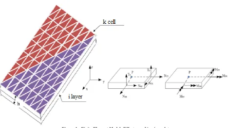
A realistic numerical prediction of the structural response of such a structure requires a rigorous three-dimensional geometric model of the system components. This model and its numerical analysis are implemented in the finite element code RE-FLEX.
Figure 1 - Finite Element Model: Efforts resulting in a plate
Where
N
xx,
N
yy represent the normal forces andN
xy the shear plane.M
xx,
M
yy represent the bending moments andxy
M
torque.T T
x,
y are the transverse shear stresses.2. CALCULATING THE ELEMENTARY FLEXIBILITY
The exact interpolation functions are obtained by writing the various external forces of any point of the finite element, which here are the internal forces of the structure, according to the nodal reduced effort. Thus, we determine the matrices representing the exact interpolation functions of effort. The external forces of 'finite element' are supposedly similar with the same nature as the internal forces of the same element.
One of the methodsto calculate the external forces of "finite element" is the linearly interpolated from the equilibrium equations of the system. Notably in our study efforts are assumed constant at every point of "finite element" and moments vary linearly as a function of
its variables (x and y in case of a plate). Thus, for a triangular plate finite element IJK, we obtained the following relationships:
- The matrix that binds the membrane and bending efforts on any point with the reduced efforts is defined by:
mf
N M
,
T
N
xx,
N
yy,
N
xy,
M
xx,
M
yy,
M
xy
T
D
cmf( , )
Ir (1)- The matrix that binds the shear efforts on any point with reduced efforts is defined by:
T
T T
x,
y
T
b
ct
rI (2)1
0
0
0
0
0
0
0
0
0
0
0
0
1
0
0
0
0
0
0
0
0
0
0
0
0
1
0
0
0
0
0
0
0
0
0
0
0
0
0
0
0
0
0
0
0
0
0
0
0
0
0
0
0
0
0
0
0
0
0
0
0
0
cmf
i j k
i j k
i j k
D
m
m
m
m
m
m
m
m
m
(3)
1 2 3 4 5 62 1 4 3 6 5
0
0
0
0
0
0
0
0
0
0
0
0
ct
b
b
b
b
b
b
b
b
b
b
b
b
b
(4)1 1 J K
y
y
b
S
, 21 K J
x
x
b
S
, 31 K I
y
y
b
S
, 41 I K
x
x
b
S
, 51 I J
y
y
b
S
, 61 J I
x
x
b
S
1 I
(
K J)
J(
I K)
K(
J I)
s
y x
x
y x
x
y
x
x
is twice the area of the triangle IJK
1,
2,
3,
I,
I,
I,
J,
J,
J,
K,
K,
K
T r
I
N N N M
xxM
yyM
xyM
xxM
yyM
xyM
xxM
yyM
xy
(5)
Where
rI the vector of nodal efforts reduced,
D
cmf( , )
and
b
ct are the matrices that represent accurate interpolation functions of the efforts membrane bending and shear respectively in the absence of apportionment. The stiffness matrix is simply the inverse of the flexibility matrix.
cmf and
T T
x,
y
are respectively the vector normal forces, effort membrane, bending moments, twisting moment andshear forces applied to the cell.
The direct connection of the finite element provides the stiffness matrix of elementary model in the local coordinate expressed by:
T 1
e e
flx
K
R
F
R
(6)
11
(
)
(
)
e pla pla
flx flx flx
F
F
cmf
F
cis
(7)Where
F
flxpla(
cmf
)
and
F
flxpla(
cis
)
are respectively the flexibilities of the matrices membrane combinationbending and shearing of the plate.
R
is the transition matrix to the system without rigid modes of deformation within fivedegrees of freedom, whose force field is represented by equation (8) and the corresponding displacements
q
are defined (eqt.9):
T
plaq r
I
F
R
(8)
eq
R u
(9)With
F
plaq
the external force exerted by a plate finite element nodal loads equivalent to the same element and
u
e the corresponding vector of nodal displacements and is given by equation (10):
0I,
0I,
0I,
I,
I,
0J,
0J,
0J,
J,
J, 0K,
0K,
0K,
K,
K
T e
x y x y x y
u
u
v
w
u
v
w
u
v
w
(10)Remark: In the simple case of a beam with two nodes with three degrees of freedom [23] the force vector corresponds exactly to the demands of the nodal finite element beam.
Flexibility matrices concerning the plates are given by:
cells 1
1
(
)
( , )
(
,
)
( , )
m T
pla
flex IJK cmf cmf K K cmf
k
F
cmf
S
D
H
D
d d
(11)
cells 1 1(
)
(
,
)
m T plaflex IJK ct ct K K ct
k
F
cisaill
S
b
H
b
d d
The matrices
1
(
,
)
cmf K K
H
and
H
ct(
K,
K)
1 are matrices named flexibilities membrane bending and shear respectively:
(
,
)
(
,
)
(
,
)
cmf K K cmf K K cmf K K
D
H
d
and
b
ct
H
ct(
K,
K)
d
ct(
,
)
mf
m mf
T
cmf K K
f
H
H
H
H
H
and
strata
1
(
,
)
N
c K K i i
i
H
h H
with strata 1 Nm i i
i
H
h H
, strata 3 3 1 11
(
)
3
Nf i i i
i
H
z
z H
andstrata
1 N
mf i i i i
H
h
H
21
0
1
0
1
1
0
0
2
i i i i i iE
H
and ' 2 '(1
)
0
2
1
(1
)
0
2
i i i i ik
E
H
k
1i i i
h
z
z
,1
(
1)
2
i
z
iz
i
The matrices
H
cmf(
K,
K)
and
H
c(
K,
K)
respectively represent the stiffness of membrane bending and shearing of the cell k of the plate, hi and Zi represent respectively the thickness and position Z layer i of the cell,E
i and
i being respectively the Young's modulus and Poisson's ratio of the corresponding layer.k
' is the shear correction factor.
'
(
,
)
,
,
,
,
,
cmf K K xx yy xy xx yy xy
d
e
e
k
k
is the vector of plane deformation, and membrane of curvatureexperienced by a cell, and
d
ct
x,
y
is the vector of deformations of the distortion in the planes (x, z) and (y, z).3. PRESENTATION OF AN ELEMENT DKT (Discrete Kirchhoff Triangle)
The DKT element defined in [1] is a finite element with three nodes and three degrees of freedom per node. It is considered in this article, as a finite element with three nodes and five degrees of freedom per node.
The rotations
x,
y are interpolated in a parabolic manner and the transverse displacementsu v w
0,
0,
0are interpolated in a linear manner [1, 2]:2
1 i 1 k
n n
x i x x k
i k n
N
P
,2
1 i 1 k
n n
y i y y k
i k n
N
P
,k
x k k
P
P C
andk
y k k
P
P S
0 0
1 i
n i i
u
N u
, 0 01 i
n i i
v
N v
, 0 01 i
n i i
w
N w
Where
C
k,S
k are the direction cosines, k is the middle of respective sides of the triangle, and are given by the side ij:C
k
(
x
j
x
i) /
L
k,S
k
(
y
j
y
i) /
L
k andL
k
(
x
j
x
i)
2
(
y
j
y
i)
2Where n is the number of nodes of the finite element, in the case of a triangular element
n
3
and functionsN
iandP
k are given by [1, 2]:1
1
3
3
(
)
(
)
2
4
i i j jk i j k x k y k x k y
k
w
w
C
S
C
S
L
(13)So: 1 2 3
1 2 3
x x x
x i i i
n
y y y
y i i i
N
N
N
u
N
N
N
(14)1
3
3
2
2
x
i k k m m
k m
N
P C
P C
L
L
, 23
23
24
k4
m xi i k m
N
N
P C
P C
, 33
3
4
4
x
i k k k m m m
N
P C S
P C S
1
3
3
2
2
y
i k k m m
k m
N
P S
P S
L
L
,N
iy2
N
ix3, 33
23
24
k4
m yi i k m
N
N
P S
P S
fori
1,...
n
III.
ANALYSIS OF A UNIFORM PLATE WITH DKT AND FLEXIBILITY (FLX)
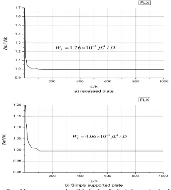
At first glance, the figure 2 represents the results obtained with FLX as we analyze a homogeneous square plate subjected to uniform load simply supported or built on the contour, for different slenderness L/h (5 to 1000). The plate is meshed with 128 (N = 8) rectangular isosceles elements (§ 2.2). The results are virtually identical with those obtained with DST and Q4γ [1] for the recessed plate (Figure 2.a). For the simply supported plate there appeared an error of about
0.5%
(Figure.2.b).Figure 2-homogeneous square plate with load uniform. Bending in the centre based on L/h
In a second step, we describe in Figures 3 to 7 some results [1, 2] and on the analysis of a homogeneous square plate subjected to a concentrated load at the center or simply supported and built on the contour.A quarter of the plate is meshed with 2, 8, 32, 128 (N = 1, 2, 4, 8) rectangular isosceles DKT elements (§ 2.3) and FLX (§ 2.2).These elements have five degrees of freedom per node and are of Kirchhoff (no transverse shear energy, the results are independent of L/h) for DKT elements and flexible elements taking into account of transverse shear (FLX) for
L h
/
24
(figures6 and 7). Figures 4 and 5 we presents the results obtained with FLX as we analyze a homogeneous square plate subjected to concentrated load simply supported or built on the contour, for different slenderness L/h (5 to 1000)for both types of mesh (there is a thin outlook of influence mesh ). The plate is meshed with 2, 8, 32 and 128 (N = 1, 2, 4,8) rectangular isosceles FLX elements (§ 2.2). Convergence can be seen for N = 8, that is to say, for a mesh of 128 elements. we observe a occurrence of an error, for the clamped plate, in the order of
0.5%
mesh A (Figure 4.a) and
0.56%
mesh B (Figure 5.a) and simply supported plate
0.3%
mesh A (Figure 4.b) and
0.31%
mesh B (Figure 5.b). In Figure 6, we provide the percentage error of the deflection at the center depending upon „N‟ number of divisions per half side. There is a monotonic convergencewith FLX (FLX model is a consistent shift, the total potential energy
EF exact
P P
E
E
and as1
.
2
P c
E
w P
, we observe that
EF exact
c c
w
w
). It is observed that DKT is a model that over-estimatesw
c. However, the monotonic convergence of DKT can‟t be demonstrated. There is also a strong influence on the orientation of the mesh with triangular elements of the type DKT and FLX. The convergence of the momentD x
M
inthe middle of the recessed side and of thereaction concentrated in the corner
(
2
)
xy B
M
in case of simply supported plate are presented in Figure 7 for both types of meshes and for DKT and FLX, (Calculations of efforts have been made directly to the nodes peaks followed by an average if the node is shared by two elements). There is a fairly rapid convergence, an influence of models and an orientation of the mesh. Meshes considered: N=1, 2, 4,8 Case N = 2
Kirchhoff solution for a concentrated load P:
3 2
/12(1
);
0.3
D
Eh
Recess :
w
c
5.6 10
3PL
2/
D
and0.1257
D x
M
P
B
D
A
y
x
C
L
L
Symmetry conditions:
0
x
on CA ; on CD
y
0
Boundary conditions:
-
Recess :
w
x
y
0
on ABD
-
Support simple:
w
x
0
on AB,
0
y
w
on BD
C
A
B
D
C
A
B
D
- Simple Support:
w
c
11.6 10
3PL
2/
D
and2
0.1219
xy B
R
M
P
Figure 3-square plate under concentrated load. Data
Figure 5-homogeneous square plate with concentrated load. Arrow in the center in terms of L / h(mesh B)
Figure 6-square plates with concentrated load at center built and simply supported. Error on a moment and a reaction in the corner for DKT and FLX
IV.
CONCLUSION
REFERENCES
1. Batoz J.L. & GOURI Dhatt « Modélisation des structures par éléments finis Volume 2 Poutres et Plaques 2. Batoz J.L. & GOURI Dhatt « Modélisation des structures par éléments finis Volume 1, Volume 2, Volume 3 »
Editions HERMES 34, rue Eugène Flachat 75017 PARIS.
3. Crisfield M.A., [1991]. “Nonlinear Finite Element analysis of solids and structures”. Vol I, John Wiley,
Chichester.
4. D. Bui, "Le cisaillement dans les plaques et les coques : modélisation et calcul", Note HI-71/7784, 1992.
5. De Ville de Goyet V., [1989]. “L‟analyse statique non linéaire par la méthode des éléments finis des structures spatiales formées de poutres à section non symétrique”. Thèse de doctorat, Université de Liège.
6. Friedman Z., Kosmatka J.B., [1993]. “An improved two-node Timoshenko beam finite element”. Computers and Structures, vol 47, no 3, pp. 473-481.
7. GOURI Dhatt et GILBERT TOUZOT « Une présentation de la méthode des éléments finis », Deuxième Edition, 1984 Maloine S.A. Éditeur 75006 Paris.
8. Ibrahimbegovic N., Frey F., [1992] “Finite element analysis of linear and non linear deformations of elastic initially curved beams”. LSC internal report 92/02, January, Lausanne.
9. Ile N., [2000]. “Contribution à la compréhension du fonctionnement des voiles en béton armé sous sollicitation sismique : apport de l‟expérimentation et de la modélisation à la conception”. These de doctorat, INSA de Lyon.
10. Ile N., Reynouard J.M., [2000] “Non linear analysis of reinforced concrete shear wall under earthquake loading”.
Journal of earthquake Engineering, Vol.4, N° 2, pp. 183-213.
11. Kotronis P., [2000]. “Cisaillement dynamique de murs en béton armé. Modèles simplifiés 2D et 3D”. Thèse de
doctorat, Ecole Normale Supérieure de Cachan.
12. Kotronis P., [2008]. « Stratégies de Modélisation de Structures en Béton Soumises à des Chargements Sévères » Mémoire pour obtenir un Diplôme d‟habilitation à diriger des recherches, UNIVERSITE JOSEPH FOURIER, au laboratoire Sols, Solides, Structures - Risques (3S-R)
13. Kotronis P., Davenne L., Mazars J., [2004]. “Poutre 3D multifibre Timoshenko pour la modélisation des
structures en béton armé soumises à des chargements sévères”. Revue Française de Génie Civil, vol. 8, issues 2-3, pp. 329-343.
14. Kotronis P., Mazars J., Davenne L., [2003]. “The equivalent reinforced concrete model for simulating the behaviour of shear walls under dynamic loading”. Engineering Fracture Mechanics, issues 7-8, pp. 1085-1097.
15. Kotronis P., Mazars J., Nguyen X.H., Ile N., Reynouard J.M., [2005b]. “The seismic behaviour of reinforced
concrete structural walls: Experiments and modeling”. 250th anniversary of the 1755 Lisbon earthquake-Proceedings, Lisbon Portugal, pp. 441-445, cd paper no 86, 1-4 november.
16. Kotronis P., Mazars J., [2005a]. “Simplified modelling strategies to simulate the dynamic behaviour of R/C
walls”. Journal of Earthquake Engineering, vol. 9, issue 2, pp. 285-306.
17. Mazars J. (1984). « Application de la mécanique de l‟endommagement au comportement non Linéaire et à la rupture du béton de structure ». Thèse de doctorat d‟état de l‟Université Paris VI.
18. NEUENHOFER A., FILIPPOU F.C., Evaluation of Non-linear Frame Finite-Element Models, Journalof Structural Engineering, Vol. 123, 7, July 1997, pp. 958-966.
19. Nguyen X.H., Mazars J., Kotronis P., Ile N., Reynouard J.M., [2006a]. “Some aspects of local and global
behaviour of RC structures submitted to earthquake - Experiments and modelling”. EURO-C 2006 Computational Modelling of Concrete Structures edited by G. Meschke, R. de Borst, H. Mang, N. Bicanic, 27th-30th March, Mayrhofen, Tyrol, Austria pp. 757-766, 2006- Austria, 27-30 March.
20. Nguyen X.H., Mazars J., Kotronis P., [2006b]. “Modélisation simplifiée 3D du comportement dynamique de
structures en béton armé”. Revue Européenne de Génie Civil, vol. 10, N° 3, pp. 361-373.
21. Przemieniecki J.S., [1985]. “Theory of matrix structural analysis”. Dover Pubns, October.
22. Stolarski H., Belyschko., [1983]. “Shear and membrane locking in C° elements”. Computers and methods in applied mechanics and engineering, vol. 41, Issue 3, December, pp. 279-296.
23. Y. BELMOUDEN (2003).Modélisation numérique de la tenue aux séismes des structures en béton armé. Article publié dans le Journal Bulletin des ponts et chaussées.