IJSRSET1733136 | Received : 19 July 2017 | Accepted : 30 July- 2017 | July-August-2017 [(3)5: 269-274]
© 2017 IJSRSET | Volume 3 | Issue 5 | Print ISSN: 2395-1990 | Online ISSN : 2394-4099 Themed Section: Engineering and Technology
269
Image Compression Using Row & Column Based Cosine Error Vector Rotation
(TCEVR) and Error Vector Rotation Using Walsh Codebook Generation In
Different Quantization Matrix
Ramandeep Sivia, Er. Vinod Kumar
Guru Kashi University, Talwandi Sabo, PunjabABSTRACT
Image compression is the application of Data compression on digital images. The objective of image compression is to reduce redundancy of the image data in order to be able to store or transmit data in an efficient form. Image compression can be lossy or lossless. Lossless compression is sometimes preferred for artificial images such as technical drawings, icons or comics. This is because lossy compression methods, especially when used at low bit rates, introduce compression artifacts. Lossless compression methods may also be preferred for high value content, such as medical imagery or image scans made for archival purposes. Lossy methods are especially suitable for natural images such as photos in applications where minor loss of fidelity is acceptable to achieve a substantial reduction in bit rate. Image compression schemes are generally classified as lossless compression schemes and lossy compression schemes. Lossless compression involves compressing data which, when decompressed, will be an exact replica of the original data. To Apply row compression technique to compress the image apply column Compression to compress the image. To Apply the Quantization Matrix to compress the image. The Different parameters such as Time taken from compression, Compression ratio, time taken for decompression and Peak Signal to noise ratio are calculated and maximum PSNR is 35.8 calculated in this work.
Keywords: Image, Compression, Lossy, Lossless, DWT
I.
INTRODUCTION
Data compression is the technique to reduce the redundancies in data representation in order to decrease data storage requirements and hence communication costs. Reducing the storage requirement is equivalent to increasing the capacity of the storage medium and hence communication bandwidth. Thus the development of efficient compression techniques will continue to be a design challenge for future communication systems and advanced multimedia applications. Data is represented as a combination of information and redundancy. Information is the portion of data that must be preserved permanently in its original form in order to correctly interpret the meaning or purpose of the data. Redundancy is that portion of data that can be removed when it is not needed or can be reinserted to interpret the data when needed. Most often, the redundancy is reinserted in order to generate the original data in its original form. A technique to reduce the redundancy of data is defined as Data compression. The redundancy in
data representation is reduced such a way that it can be subsequently reinserted to recover the original data, which is called decompression of the data.
II.
A DATA COMPRESSION MODEL
any natural audio or speech data. These redundancies in data representation can be reduced in order to achieve potential compression.
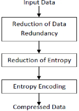
Removal or reduction in data redundancy is typically achieved by transforming the original data from one form or representation to another. The popular techniques used in the redundancy reduction step are prediction of the data samples using some model, transformation of the original data from spatial domain such as Discrete Cosine Transform (DCT), decomposition of the original data set into different sub bands such as Discrete Wavelet Transform (DWT), etc. In principle, this step potentially yields more compact representation of the information in the original data set in terms of fewer coefficients or equivalent. In case of loseless data compression, this step is completely reversible. Transformation of data usually reduces entropy of the original data by moving the redundancies that appear in the known structure of the data sequence.
Figure 1 : A Data Compression Model
The next major step in a lossy data compression system is to further reduce the entropy of the transformed data significantly in order to allocate fewer bits for transmission or storage. The reduction in entropy is achieved by dropping no significant information in the transformed data based on the application criteria. This is a nonreversible process because it is not possible to exactly recover the lost data or information using the inverse process. This step is applied in lossy data compression schemes and this is usually accomplished by some version of unitization technique. The nature and amount of quantization dictate the quality of the
reconstructed data. The quantized coefficients are then lossless encoded using some entropy scheme to compactly represent the quantized data for storage or transmission. Since the entropy of the quantized data is less compared to the original one, it can be represented by fewer bits compared to the original data set, hence compression is accomplished.
The decomposition system is just an inverse process. The compressed code is first decoded to generate the quantized coefficients. The inverse quantization step is applied on these quantized coefficients to generate the approximation of the transformed coefficients. The quantized transformed coefficients are then inverse transformed in order to create the approximate version of the original data. If the quantization and inverse quantization steps are absent in the codec and the transformation step for redundancy removal is reversible, the decompression system produces the exact replica of the original data and hence the compression system can be called a lossless compression system.
III.
IMAGE SEGMENTATION
In computer vision, image segmentation is the process of partitioning a digital image into multiple segments (sets of pixels, also known as superpixels). The goal of segmentation is to simplify and/or change the representation of an image into something that is more meaningful and easier to analyze.[1][2] Image segmentation is typically used to locate objects and boundaries (lines, curves, etc.) in images. More precisely, image segmentation is the process of assigning a label to every pixel in an image such that pixels with the same label share certain characteristics.
IV.
ROI BASED COMPRESSION TECHNIQUES
A number of methods are available for compressing medical images. Every method has their own advantages and disadvantages. Some of the major algorithms being used are as following:
General Scaling Method
The principle of the general scaling method is to shift coefficients so that the bits associated with the ROI are placed in higher bit planes than the bits associated with the background. Then, during the embedded coding process, the most significant ROI bit planes are placed in the bit stream before any background bit planes of the image. Depending on the scaling value, some bits of the ROI coefficients might be encoded together with non-ROI coefficients.
MAXSHIFT Method
the scaling value is computed in such a way that it makes it possible to have arbitrarily shaped ROIs without the need for transmitting shape information to the decoder and without the need for calculating the ROI mask. This means also that the decoder does not have to perform ROI mask generation either.
SPIHT Method
The input images are segmented into the foreground and background, respectively, and a chain code-based shape coding scheme is used to code the ROI's shape information. Then, the critically sampled shape- adaptive integer wavelet transforms (IWTs) are per- formed on the foreground and background image separately to facilitate lossy-to-lossless coding. Finally, the shape-coding bit stream, the foreground bit stream, and the background bit stream are combined into a single bit stream.
Discrete Cosine Transform
Discrete Cosine Transform (DCT) is used to achieve high compression ratio without degrading of quality.
Adaptive Arithmetic entropy Coding
Arithmetic coding is different from other coding methods for which we know the exact relationship
between the coded symbols and the actual bits that are written to it. It codes one data symbol at a time, and assigns to each symbol a real-valued number of bits.
V.
METHODOLOGY
The research is to compress the color images. It is based upon GUI (graphical user interface) in MATLAB. It is an effort to further grasp the fundamentals of MATLAB and validate it as a powerful application tool. There are basically different files. Each of them consists of m-file and figure file.
Huffman Coding
From Shannon's Source Coding Theory, it is known that a source can be coded with an average code length close to the entropy of the source. In 1952, D.A. Huffman [13] invented a coding technique to produce the shortest possible average code length given the source symbol set and the associated probability of occurrence of the symbols. Codes generated using these coding techniques are popularly known as Huffman codes. Huffman coding technique is based on the following two observations regarding optimum prefix codes.
The more frequently occurring symbols can be allocated with shorter code words than the less frequently occurring symbols.
The two least frequently occurring symbols will have code words of the same length, and they differ only in the least significant bit.
Average length of these codes is close to entropy of the source. Assume that there are m source symbols {s1, s2, ..., sm} with associated probability of occurrence {p1, p2, ..., pm}. Using these probability values, generate a set of Huffman codes of the source symbols. The Huffman codes can be mapped into a binary tree, popularly known as the Huffman tree. The algorithm to generate Huffman tree and hence the Huffman codes of the source symbols can be shown as below:
Produce a set N = {N1, N2, ..., Nm} of m nodes as leaves of a binary tree. Assign a node Ni with the source symbol si, i = 1, 2, ..., m and label the node with the associated probability pi.
Find the two nodes with the two lowest probability symbols from the current node set, and produce a new node as a parent of these two nodes.
Label the branch of one child node of the new parent node as 1 and the branch of the other child node as 0.
Update the node set by replacing the two child nodes with smallest probabilities by the newly generated parent node. If the number of nodes remaining in the node set is greater than 1, go to Step (ii).
Transverse the generated binary tree from the root node to each leaf node Ni, i = 1, 2... m, to produce the codeword of the corresponding symbol si, which is a concatenation of the binary labels (0 or 1) of the branches from the root to the leaf node.
Figure 2 : Huffman tree construction
VI.
RESULTS AND DISSCUSSION
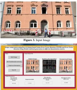
The SPIHT algorithm was implemented using MATLAB. The algorithm described in this section such as compressing using SPIHT have been applied on standard images of size 256 X 256. The results were evaluated both qualitatively. In order to evaluate performance of the algorithm qualitatively the clean image are used for compressing. In this algorithm, we used the wavelet method and Lossy technique with Huffman coding for getting out up to 2-level decomposition of an image in which actually our image is compressed. The recovered image is visually very close to the original mage. If all the bit planes are used then the original image is recovered completely (up to rounding errors). Although the MATLAB version of the row and column transformation runs slow no attempt was done to optimize the code as for instance. Familiarity with MATLAB and accessible tools in it will allow them to easily modify the code and reduce development time. Below figure shows the original image which is to be compressed using DCT based Quantization algorithm, next figure shows the one Level decomposition of sub-banding with finding out
approximation , vertical , horizontal and diagonally pixels resolution so that image threshold is calculated and original image can we reconstructed with reduction in size.
Figure 3. Input Image
Figure 4: Column Level compression with DWT technique
The figure 4. is the image compression with the help of Quad tree compression and decompression . In this the image is compressed with the help of column level compression. The different parameters are displayed in the edit box.
Name of image
Time for compressi
on
Compressi on ratio
Time taken for decompressi
on
PSN R
4.jpg 116.3.8 7.11 163..7 30.3.
7.jpg 115.8 9.8 113.8 32.5
16.jpg 102.5 16.8 90.8 35.8
123.jpg 152.6 15.2 110.5 35.0
face1.jpg 125.8 12.5 123.8 40.5
face2.jpg 122.5 18.8 110.8 45.8
face3.jpg 100.6 13.2 90.5 38.0
face8.jpg 95.8 15.8 80.8 42.5
imag-105.jpg
105.8 13.5 98.8 32.5
Image34.j pg
Figure 5 : Time for compression
Figure 6 : Compression Ratio
VII.
CONCLUSION
Image compression is used for managing images in digital format. This has been focused on the Fast and efficient lossy coding algorithms JPEG for image Compression/Decompression using Discrete Cosine transform. We also briefly introduced the principles behind the Digital Image compression and various image compression methodologies .and the jpeg process steps including DCT, quantization , entropy encoding. In future this work can be extended to various levels of decomposition and medical video compression. The imaging devices continue to generate more data per patient, often large imaging. These data need long term storage and efficient transmission so there is a need to compress medical images. The various methods are used to compress the images. In all the research work we have studied the various techniques; these techniques have several pros and cons. These are due to the methods that are used to compress the medical images. Imaging helps a lot to represent the internal problem of body in visual manner. Various medical diagnosing techniques are using digital images of
human body as the deciding factors for next medical treatment. The new techniques are enhanced to compress the medical image so that the problems encountered in the previous study can be solved.
VIII.
FUTURE WORK
The work, up to the current stage has shown how wavelet transforms can be implemented to scale and compress image into a multi-resolution analysis representation. The results obtained have shown significant reduction but the images tend to smear with more decomposition levels. Hence, there are still areas that can be done to improve this work. The threshold procedures can be used in the algorithm to further improve Compression.
IX.
REFERENCES
[1]
Prof. A. A. Shaikh et.al. “Huffman Coding Technique for Image Compression” COMPUSOFT, An international journal of advanced computer technology, 4 (4), April-2015.[2]
Dr. M. Moorthi et.al. “A Method for Compression of Solar Image using Integer Wavelet Transform” International Journal for Research in Applied Science & Engineering Technology (IJRASET), Volume 2 Issue XII, December 2014.[3]
Sathish Kumar.S et.al “Medical Image Compression Based On Automated Roi Selection For Telemedicine Application” International Journal Of Engineering And Computer Science ISSN:2319-7242 Volume 3 Issue 1, Jan 2014.[4]
A.M.Raid et.al. “Jpeg Image Compression Using Discrete Cosine Transform - A Survey” International Journal of Computer Science & Engineering Survey (IJCSES) Vol.5, No.2, April 2014.[5]
Miss. S.S. Tamboli et.al. “Image Compression Using Haar Wavelet Transform” International Journal of Advanced Research in Computer and Communication Engineering Vol. 2, Issue 8, August 2013.[6]
Mridul Kumar Mathur et.al. “Lossless Huffman Coding Technique For Image Compression And Reconstruction Using Binary Trees” Mridul Kumar Mathur et al,Int.J.Comp.Tech.Appl, IJCTA | JAN-FEB 2012[7]
Mamta Sharma et.al. “Compression Using Huffman Coding” IJCSNS International Journal0 50 100 150 200 7.jp g 16 .jp g 12 3.jp g fac e1.jp g fac e2.jp g fac e3.jp g fac e8.jp g im ag-… Im age3 4 .jp g
Time for compression 116.3.8
of Computer Science and Network Security, VOL.10 No.5, May 2010.