https://doi.org/10.5194/ms-9-277-2018
© Author(s) 2018. This work is distributed under the Creative Commons Attribution 4.0 License.
Mechatronic design and genetic-algorithm-based MIMO
fuzzy control of adjustable-stiffness
tendon-driven robot finger
Izzat Al-Darraji1,2, Ali Kılıç1, and Sadettin Kapucu1
1Mechanical Engineering Department, University of Gaziantep, Gaziantep, Turkey 2Automated Manufacturing Department, University of Baghdad, Baghdad, Iraq
Correspondence:Izzat Al-Darraji ([email protected])
Received: 28 February 2018 – Revised: 29 July 2018 – Accepted: 20 August 2018 – Published: 28 August 2018
Abstract. This work presents a detailed design of a three-jointed tendon-driven robot finger with a cam/pulleys transmission and joint Variable Stiffness Actuator (VSA). The finger motion configuration is obtained by deriv-ing the cam/pulleys transmission profile as a mathematical solution that is then implemented to achieve contact force isotropy on the phalanges. A VSA is proposed, in which three VSAs are designed to act as a muscle in joint space to provide firm grasping. As a mechatronic approach, a suitable type and number of force sensors and actuators are designed to sense the touch, actuate the finger, and tune the VSAs. The torque of the VSAs is con-trolled utilizing a designed Multi Input Multi Output (MIMO) fuzzy controller. The fuzzy controller input is the force sensors’ signals that are used to set the appropriate VSA torque. The fuzzy controller parameters are then tuned using a genetic algorithm as an optimization technique. The objective function of the genetic algorithm is to avoid unbalance torque in the individual joints and to reduce the difference between the values of the supplied VSAs torques. Finally, the operation of the aforementioned finger system is organized through a simple control algorithm. The function of this algorithm is to enable the detection of the unknown object and simultaneously automatically activate the optimized fuzzy controller thus eliminating the necessity of any external control unit.
1 Introduction
The evolution and development of the robot hand has played a strategic role in the robot revolution as it is essential in numerous different applications such as service robots. Re-searchers continue to improve the performance of the robot hand through innovative and creative design together with the careful selection of suitable control algorithm in conjunction with the used sensors and actuators. A tendon-driven mech-anism is being suggested in several robot hands due to its essential properties of: (1) driving the motion of the fingers by wire cables similar to the muscles of real human hands; (2) generating the required tension to actuate the finger by motors in the base of the hand rather than the joints of fingers which has enabled a reduction in finger size; and (3) having low coefficient of friction, mass, and backlash (Kino et al., 2004). In finger manipulators, the large difference between the contact forces on the phalanges results in damage to the
introduced a technique to design a three-phalanx underactu-ated mechanism of two pairs of curved gears to achieve force isotropy. The kineto-static analysis is applied to achieve an isotropic finger. The analysis of the suggested mechanism showed a typical isotropy between the intermediate phalanx and the distal phalanx. Producing the introduced mechanism practically is suggested as a future work. On the other hand, when used in grasping applications, conventional tendon-driven mechanisms have the disadvantage of a relatively poor grasping ability. For instance, a simple actuating tendon fin-ger has a low grasp forces (Birglen et al., 2008) which re-stricts the holding of relative heavy objects, or preventing objects from falling when the robot hand moves at a rela-tive high speed. Compliant mechanisms have been suggested by researchers as a solution to enhance the grasping perfor-mance of tendon-driven mechanisms. Bundhoo et al. (2009) developed a novel artificial finger using compliant tendons and wires made from a type of shape-memory-alloy. They suggested a compliant tendon which is constructed using a spring-slack component with integrated shape memory alloy wires. This compliant mechanism provided the finger with the ability of work similarly to a natural finger with real mus-cles. These muscles represented the agonist-antagonist pairs during flection and abduction of the proximal phalanx and the flection of the intermediate phalanx. Ozawa et al. (2009) introduced a new hybrid mechanism of passive and active tendons to improve the function of a two-linked finger in such a way that the produced finger could mimic a real finger figuration during the contact process. This mechanism con-tained three tendons. The first tendon was active while the others were passive. The drawback of this mechanism was the disability of generating high torque approaches. Later, in a proceeding work, Ozawa et al. (2014) introduced the design of a new robot finger which has real finger characteristic fea-ture of absorbing environment forces during contact process. The presented mechanism included six tendons. It contained two passive type tendons which are arranged in a special way between the tip of distal phalanx and the intermediate phalanx and the remaining four were active tendons. In and Cho (2013) introduced a finger mechanism whose primary characteristics are a fast closing sequence and large contact forces during the grasp phase. The aforementioned two fea-tures are accomplished by integrating an adjustable arm el-ement with a tendon driven mechanism. The tendon driven mechanism has a variable transmission ratio which varies with respect to the varying of the moment arm element. The moment of the arm element is specified by the manner in which it is mounted along the path of wire and the joint. Through a two-finger gripper design and development of en-velope grasping, Ciocarlie et al. (2013) established a stable grasping operation for large objects. The introduced mecha-nism applied active flexor tendon, joint spring, and extensor tendon. The functionality of the gripper is accomplished by optimizing the path of the active flexor tendon. Furthermore, the applied passive springs supplied the extended force. Kuo
et al. (2015) designed a novel human like compliant finger through integrating compliant material in joints with a ten-don routing. The geometry deign of the compliant materials provided the designed finger the functionality of compliance behavior like the joints of human hand. The tendon routing is arranged in a similar way to the real human finger. As a re-sult, the finger had robustness during the grasping and manip-ulation operation. In control view, fuzzy logic algorithm with tendon-driven robot hands have been implemented to control underactuated mechanisms. Hristu et al. (1994) controlled an underactuated multi-fingered robot hand using fuzzy al-gorithm and compared the results with tradition Proportional Integral Derivative (PID) controller. The introduced study in-cluded discussion of both the position of joints and force of touching sensors. In not combined position and force con-trol, the results showed that the performance of the fuzzy controller was better that the PID controller. In control of hybrid position/force behavior, Hristu et al. (1994) showed that an extra procedure is needed to tune the parameters of the hybrid fuzzy controller in order to overcome the prob-lem of weighting between commands of position and force. Birglen and Gosselin (2005) used fuzzy logic controller to control underactuated finger. The tactile and position infor-mation are used in the implemented fuzzy controller. The re-sults showed that an enhanced force control can be obtained using fuzzy controller where the underactuated finger could hold a fragile object with a real human finger and get about it with a grip approach.
others are applied to compute the motor position commands and the associated time-varying torque with stiffness profiles. Albu-Schäffer et al. (2010) designed a simple gain sched-uled state feedback controller for a new two joints variable compliance arm. The applied control algorithm is based on vibration damping. Adjusting the mechanical damping via the suggested control method treated the problem of both the low damping springs and the high tuning of VSA stiff-ness. Palli and Melchiorri (2011) presented the control of the force interaction with the environment of an adjustable joint stiffness robot manipulator. It is assumed that the interaction force is not directly measurable, but the proposed controller can estimate the force. Also, the problem of simultaneous control of both the position and the stiffness trajectory in the robot workspace is investigated. Braun et al. (2012) proposed an optimal control formulation to a compliant robotic. The motor position commands and the associated time-varying torque with stiffness profiles are computed optimally. As a result, the optimal stiffness of VSA is obtained based on the dynamics of the compliant robot system. Then, the optimal stiffness is applied to independently check the control advan-tage between stiffness and torque.
This paper examines the grasping mechanism in existing VSAs joints and tendon-driven actuating with the objective to control firm grasp. We have analytically and experimen-tally investigated a prototype robot hand called as Cam Pul-ley Robot Hand (CPRH) with two identical fingers called a Cam Pulley Robot Finger (CPRF). The aim of this work is to treat the low grasp forces problem using a suggested mecha-nism of VSA which is integrated with a tendon-driven mech-anism. The geometric design of the tendon-driven mecha-nism is derived mathematically to regulate the motion of the joints together in a special order to achieve isotropic force on phalanges. Hence, the designed finger has close contact forces by phalanges on the grasped objects with the essen-tial particularity that grasp forces on the phalanges can be improved and adjusted by tuning the stiffness matrix of the VSAs. The VSAs are designed in the joints to enhance the property of grasping by increasing the torque in the joints through a fuzzy logic controller. The fuzzy logic controller is a MIMO who’s inputs and outputs are the force signals on the phalanges and the torque of VSAs, respectively. The per-formance of the fuzzy controller is optimized using genetic algorithm in order to reduce the large difference between the values of VSA torque which can cause damage to the grasped objects. The VSAs adjust their torque once the finger has de-tected the grasped object and has stopped its motion. This is essential to ensure that the VSA will not affect the mo-tion of the designed tendon-driven mechanism. Specifically, a control algorithm is carried out to synchronous the opera-tion of the menopera-tioned mechanical parts, electronic hardware, and the fuzzy logic controller. This algorithm is written in a simple way such that it: stops the motion of the finger when it detects objects, and activates the fuzzy logic controller to support appropriate VSA torque during the grasp phase.
Fi-nally, the suggested finger mechanism also facilitates actuat-ing both the motion of the factuat-inger and the VSA by mountactuat-ing motors in the fixed part under the palm. This is essential in a robot hand to reduce the finger size.
This paper is organized as follows: In Sect. 2, details of producing CPRF with deriving mathematical equations of the model are introduced. Next, in Sect. 3, the description of the layout and the hardware architecture of the sensors and actuators are explained along with the assembly of the pro-totype robot hand. Section 4 shows the designed fuzzy logic controller, the optimized genetic algorithm, and the applied control algorithm. In Sect. 5, the performance of the designed prototype is presented in tests. In Sect. 6, the results of this work are discussed. Finally, in Sect. 7, concluding remarks are made and the possible direction of the future research are stated.
2 Producing CPRF
2.1 CPRF Mechanism
Two distinguishing stages exist in the grasping operation. The first is the planning stage. This period starts from the non-contact position until the moment where the fin-ger comes into contact with the grasped object. The second one is the holding stage, which is responsible for holding the object by applying appropriate forces between the ob-ject and the finger on contact points (Buss et al., 1996). The proposed CPRF has accomplished the aforementioned two stages thanks to the design of the finger mechanism. In gen-eral, the mechanism contains three links of three joints who’s angles change relatively to each other by a tendon-driven mechanismin the planning stage. The proposedVSA mech-anismis placed on the other side of each joint to act as an actuator of variable stiffness to improve the grasping forces on phalanges for the holding stage.
2.1.1 Tendon-driven Mechanism
The tendon-driven mechanism is implemented to achieve force isotropy in the planning stage by using cams instead of pulleys. This tendon-driven mechanism is shown in Fig. 1a where pulley 1 is free to rotate of radiusr1, and pulley 2 is
a double type free to rotate of radiir2andr3, while the third
one has a radiusr4which is fixed to link (BC). Actuating the
tendon, by rotating a motor in a clockwise direction, results in rotating the three links relatively during closing motion to grasp an object. Opening motion occurs by rotating the same motor in an anticlockwise direction due to the effect of ten-sion springs of stiffness (K10,K20,K30) shown in Fig. 1a. The
be-Figure 1.CPRF principle of operation(a)tendon actuating(b)VSA.
comes as;
l1=l2+l3 (1)
wherel1,l2, andl3are the length of link (OA), link (AB), and
link (BC), respectively. Consequently, golden ratioϑis used here to calculate the ratio between the lengths of two consec-utive links (Rizk, 2007; Dandash et al., 2011; Ask, 2016);
l3=ϑ l2=ϑ2l1 (2)
assuming that the phalanges contact the object along their entire length. Hence, the pressure, i.e. the pressure produced by contact forces on the length of finger links, is; To add a, b, c to the numbering:
p1=
f1
bl1
(3a)
p2=
f2
bl2
(3b)
p3=
f3
bl3
(3c)
whereb is the width of the finger. In order to get a uniform contact pressure during grasping, Eq. (3a, b) is equalized. In this way;
f1
bl1 = f2
bl2
, f1=
l1
l2
f2 (4)
from Eq. (2), the ratio betweenl1andl2is;
l1
l2 =ϑ,
hence, Eq. (4) becomes;
f2=
1
ϑf1 (5)
also, Eq. (3b, c) is equalized to get a uniform contact pres-sure. Thus;
f2
bl2 = f3
bl3
, f2=
l2
l3
f3, (6)
from Eq. (2), the ratio betweenl2andl3is;
l2
l3 =ϑ,
hence, Eq. (6) becomes;
f3=
1
ϑf2. (7)
Supporting distributed pressure on the grasped object, to avoid the damage to the grasped object, is achieved by considering the force isotropy between contact forces in Eqs. (5) and (7). These two equations are used later in the geometry design of finger in Sect. (2.2) to enable the config-uration motion of finger contact the grasped object with force isotropy property.
2.1.2 VSA Mechanism
Table 1.Physical properties for the torsion spring of material stain steel.
Name Value
Wire diameter (d) 0.5 mm
Outer diameter 5.8 mm
Initial mean diameter (D1) 5.3 mm Number of body coils (Nb) 3 Number of active coils (Na) 3 Modulus of elasticity (E) 2×10⁵N mm−2
Figure 2.Supplied torque by VSA corresponding to the change of stiffness with respecting to the deflection.
the mean diameterDmof the spring is reduced according to
the following equation (Shigley and Mischke, 2004);
Dm=
D1Nb
Nb+1θ
, (8)
assumingithe index of joint (wherei=1, . . . ,3), the stiff-ness rate per degree is changed;
ki =
π Ed4
64·180DmNA
, (9)
where1θ is the difference between the angleθ of the link and the free end side of the torsion springθ0shown in Fig. 1b. The link is considered fixed because in the control approach the stiffness of the VSA is adjusted only in the hold position. During change the stiffness, the supplied torque by VSA at each joint becomes;
Ti=ki1θ. (10)
Hence, tuning the stiffness of VSA gives rise to a corre-sponding torque as shown in Fig. 2.
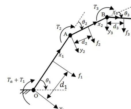
Figure 3.CPRF geometric model with input and output forces.
2.2 CPRF Design
Geometric model of Fig. 1a with input and output forces is presented in Fig. 3 and its parameters are detailed in Ta-ble 2 (wherei=1, . . . ,3). Geometric parameters of mech-anism parts are set to avoid undistributed contact forces on phalanges. Specifically, in the kineto-static analysis, contact forces are derived here from the input and output powers of the CPRF. Then, these contact forces are substituted in Eqs. (5) and (7) in order to find the relations between radii of pulleys which achieve force isotropy. Next, some pulleys are replaced with cams so that the relative motion between pha-langes is regulated to reach the grasped object with close con-tact forces. Finally, the profile of cams is obtained by some mathematical calculations.
LetPinandPoutdenote the input and output power to the
robot finger, respectively. These powers are obtained as;
Pin=(Ta−T1)θ˙1−T2θ˙2−T3θ˙3,
Pin= Ta−k1θ10θ˙1−k2θ20θ˙2−k3θ30θ˙3, (11)
Pout=
" f
1
f2 f3
#T" d
1 0 0
w1 d2 0
w2 d3+l2cosθ3 d3
#
˙
θ1
˙
θ2
˙
θ3
, (12)
where
w1=d2+l1cosθ2
w2=d3+l1cos (θ2+θ3)+l2cosθ3,
equalizing Eqs. (11) and (12), contact forces become;
f1= Ta−k1θ10 1
d1
−h1+h2
Table 2.Parameters of CPRF analysis.
Symbol Parameter details
li Length of link
Ta Applied torque by the actuator di=li/2 Contact force location (considered
at the middle distance for each link) fi Contact force
ki Stiffness of VSA
θi The angle of rotation of linki θi0 The angle of rotation of torsion
spring pulley side
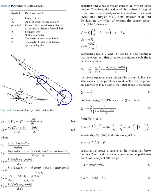
Figure 4.Geometrical analysis of cam 4 profile.
f2=h5 Ta−k1θ10
−k2θ2
0
d2
+h6, (14)
f3=
r2r4(Ta−k1θ10)
d3r1r3
−k3θ3
0
d3
, (15)
where
h1=
r2(d2+l1cosθ2)
d1d2r1
,
h2=
l1r2r4(d3cosθ2−d2cos (θ2+θ3))+l2cosθ2cosθ3
d1d2d3r1r3
,
h3=
k2θ20(d2+l1cosθ2)
d1d2
,
h4=
k3θ30l1(d3cosθ2−d2cos(θ2+θ3)+l2cosθ2cosθ3)
d1d2d3
,
h5=
r2
d2r1
−r2r4(d3+l2cosθ3)
d2d3r1r3
,
h6=
k3θ30(d3+l2cosθ3)
d1d3
,
The springs in the tendon-driven mechanism have low stiffness when all phalanges make contact with the grasped object, compared with the actuation torque. In addition, the
actuation torque has to remain constant to have an isotropic design. Therefore, the action of the springs is negligible in the kineto-static analysis of tendon-driven mechanisms (Krut, 2005; Birglen et al., 2008; Dandash et al., 2011). By ignoring the effect of springs, the contact forces in Eqs. (13–15) become;
f1=Ta 1
d1
−h1+h2
+h3−h4, (16)
f2=h5Ta, (17)
f3=
r2r4Ta
d3r1r3
, (18)
substituting Eqs. (17) and (18) into Eq. (7), to find the rela-tion between radii that gives force isotropy, yields the ratio betweenr3andr4;
N1=
r3
r4 =l2
l3
ϑ+(l3+2l2cosθ3)
l2
, (19)
the above equation maps the profile of cam 4. For a con-stant radiusr3, the profile of cam 4 is obtained by
geometri-cal analysis of Fig. 4 with some geometri-calculations. Assuming;
Q= −r4
r3
, (20a)
and rearranging Eq. (19) in term ofQ, we obtain;
Q= −l3
l2
1
ϑ+(l3+2l2cosθ3) l2
, (20b)
from Fig. 4,βis;
β=sin−1r3−r4
l2
=sin−1r3
l2 −r4
l2
=sin−1r3
l2
1−r4
r3
,
substituting Eq. (20a) in this formula, yields;
β=sin−1r3
l2
(1+Q) (21)
selecting the vector u parallel to the tendon path between points (H3H4) and the vectorvparallel to the path between
point (H4) and joint (B), we get;
ux4=cos(β+θ3), (22a)
uy4= −sin(β+θ3), (22b)
vx4=sin(β+θ3), (22c)
assumeJ an arbitrary point on the tendon, then;
BJ =r4v¯+uu,¯ (23)
using the vectors in Eq. (22a–d), Eq. (23) becomes;
BJx4= −r3Qsin(β+θ3)+ucos(β+θ3), (24a)
BJy4= −r3Qcos(β+θ3)−usin(β+θ3), (24b)
profile of cam 4 is determined by values ofuthat satisfies the following determinant matrix (Dandash et al., 2011);
1=det δBJ
δθ3 ;δBJ
δu
!
=0, (25)
the elements of the determinant matrix are obtained from Eq. (24a, b);
δBJ δθ3 =
−u[cos (β+θ3)]0−r3[Qsin (β+θ3)]0 −u[sin (β+θ3)]0−r3[Qcos (β+θ3)]0.
δBJ δu =
cos(β+θ3) −sin (β+θ3.)
then, the determinant in Eq. (25) is calculated as follow;
1= −u 1+β0−r3Q0=0, (26)
rearranging the Eq. (26) in term ofu, we get;
u= −r3Q
0
1+ ∂β ∂QQ
0,
referring to Eqs. (20b) and (21);
Q0=δQ
δθ3 =d3
d2
l2sinθ3 d2
ϑ+(d3+l2cosθ3) d2
2,
∂β ∂Q=
r3/l2 r
1−r3 l2(1+Q)
2,
In this way, the profile of cam 4 in Eq. (24a, b) is obtained as;
BJx4=r3
1
N1
sin (β+θ3)+
−r3Q0
1+∂Q∂βQ0
!
cos(β+θ3), (27a)
BJy4=r3
1
N1
cos (β+θ3)−
−r3Q0
1+ ∂β ∂QQ
0
!
sin (β+θ3). (27b)
The next step is to obtain the profile of cam 2. Getting the profile of cam 2 is more complicated than cam 4 profile be-cause cam 2 is free to rotate, while cam 4 is fixed to distal
Figure 5.Geometrical analysis of cam 2 profile.
phalanx. Since cam 2 is free to rotate on the joint (A); there-fore, we should find a relation between the free rotation of cam 2 and the rotation of link 2. Assuming cam 2 rotates with an angleθcam 2as shown in Fig. 5, hence;
˙
θcam 2−N1θ˙3= ˙θ2,
θcam 2−
d2
d3
ϑ+1
θ3−
l2sinθ3
d3
=θ2, (28)
let;
w3= d
2
d3
ϑ+1
θ3+
l2sinθ3
d3
,
then;
θ2=θcam 2−w3, (29)
substituting Eqs. (16) and (17) into Eq. (5), to find the rela-tion between radii that gives force isotropy, yields the ratio betweenr1andr2;
N2=
r2
r1
=l2l3N1
h7
, (30)
where;
h7=N1l1l3ϑ−ϑ l1l3−2ϑ l1l2cosθ3+l2l3N1
+2l1l3N1cosθ2−2l1l3cosθ2+2l1l3cos (θ2+θ3) −4l1l2cosθ2cosθ3,
the ration between pulleys in Eq. (30) is a function ofN1,
l1,l2,l3,θ2,θ3, andϑ. Eq. (30) maps the profile of cam 2.
For a constant radius r1, the profile of cam 2 is obtained
by geometrical analysis of Fig. 5 with some calculations as follows:
let;
r2=
M1
M2
then merging Eq. (31) with Eq. (30), yields;
M1=d2d3N1r1, (32)
and
M2=
N1ϑ d1d3−ϑ d1d3−ϑ d1l2cosθ3+d2d3N1
+l1d3N1cos (θcam 2−w3)−l1d3cos (θcam 2−w3)
+l1d2cos(θcam 2−w3+θ3)
−l1l2cos(θcam 2−w3) cosθ3,
(33)
As shown in Fig. 5, the angle between link (OA) and the tendon is;
sinγ=r1−r2
l1
, (34)
letJ1the nearest point of the tendon to the joint (A);
AJ1x4=r2cos(γ+θcam 2),
AJ1y4=r2sin(γ+θcam 2),
letJ2be any point of the tendon;
AJ2=AJ1+λu,
then;
AJ2x4=r2cos(γ+θcam 2)+λcos π
2 +γ+θcam 2
, (35a)
AJ2y4=r2sin(γ+θcam 2)+λsin π
2 +γ+θcam 2
, (35b)
by applying the same procedure in deriving the path of cam 4, the profile of cam 2 is obtained byλ. Assume;
det δAJ2
δθcam 2 ;δAJ2
δλ
!
=0, (36)
according to Eq. (35a, b);
δAJ2
δθcam 2 = ˙
r2cos(γ+θcam 2)−r2sin (γ+θcam 2)
(γ˙+1)−λ(γ˙+1) sin(π
2 +γ+θcam 2)
˙
r2sin(γ+θcam 2)+r2cos (γ+θcam 2)
(γ˙+1)+λ(γ˙+1) cos(π
2 +γ+θcam 2),
δAJ2 δλ = cos π
2 +γ+θcam 2
= −sin(γ+θcam 2)
sinπ
2 +γ+θcam 2
=cos(γ+θcam 2)
,
substituting these two formulas in Eq. (36) and after calcu-lating of the determinant matrix, we get;
1 λ = δγ δr2 + 1 δr2 δθcam 2
, (37)
to find δδγr 2 and
δr2
δθcam 2,r2is obtained from Eq. (34);
r2=r1−l1sinγ ,
thus;
δr2
δγ = −l1cosγ , (38)
according to Eq. (31);
r2=
M1
M2
,
hence;
δr2
δθcam 2 =
˙
M1M2−M1M˙2
M22 , (39)
referring to Eqs. (32) and(33);
˙
M1=0,
˙
M2=
−l1d3N1sin (θcam 2−w3)+l1d3sin (θcam 2−w3) −l1d2sin(θcam 2−w3+θ3)
−l1l2sin(θcam 2−w3) cosθ3,
now substituting Eqs. (38) and (39) in Eq. (37), yields;
λ= −l1cosγ M1 ˙
M2
M1M˙2+l1cosγ M22
, (40)
Hence, cam 2 profile in Eq. (35a, b) is obtained as;
AJ2x4=(r1−l1sinγ) cos (γ+θ2+N1θ3) +λcosπ
2 +γ+θ2+N1θ3
, (41a)
AJ2y4=(r1−l1sinγ) sin (γ+θ2+N1θ3) +λcosπ
2 +γ+θ2+N1θ3
(41b)
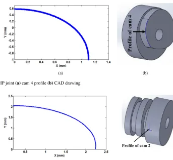
Figure 6.Cam on DIP joint(a)cam 4 profile(b)CAD drawing.
Figure 7.Double cam pulley on PIP joint(a)cam 2 profile(b)CAD drawing.
3 Robotic Hand System
3.1 Sensorimotor System
A suitable sensorimotor layout is proposed, designed, and programmed with its computer interface circuit to sense the grasped objects and actuate the mechanical parts of the designed CPRF in CPRH. The overall layout is shown in Fig. 9a, in which, the motor of the tendon-driven mecha-nism is controlled by force sensors which in turn adjust the stiffness of the VSAs. A Force Sensitive Resistor (FSR) sen-sor is used to sense touch on the phalanges. The sensen-sor type (FSR 402 Short) of 15.24 mm diameter is applied for prox-imal phalanx and type (FSR 400 Short) of 6.35 mm diame-ter is applied for indiame-termediate and distal phalanges (Pololu Force Sensing Resistor, 2018). The FSR sensor changes its resistance depending on the magnitude of the force applied to its surface. In order to be able to read the sensor signals, an electronic circuit is designed that pinned the analog sig-nal from a voltage divider circuit of a resistance 10 kto the Arduino 2560 microcontroller board analog signal pins (A0, . . ., A5). Additionally, the designed electronic circuit assists in producing more output changes with respect to fewer changes of FSR resistance to overcome the nonlinear-ity of FSR sensors. To obtain proper experimental data, it was
important to calibrate the force sensors employed in the robot finger. For all FSR 400 series sensors used, obtaining force unit from the resistance of the sensor is implemented depen-dent on the number of analogue to digital converter (ADC) bits and voltage divider circuit. Using: (1) the Arduino 2560 microcontroller board of 10 bits; and (2) the range of map-ping voltage between 0–5000 mV, we get;
VFSR
5000=
Vanalog
1023 , (42a)
whereVFSRandVanalogare the voltage across the FSR sensor
and the analogue voltage of FSR sensor, respectively. Con-sidering the voltage divider circuit, we obtain;
VFSR=Vcc·
R R+RFSR
(V), (42b)
RFSR=
(Vcc−VFSR)R
VFSR
(), (42c)
GFSR=
1 000 000
RFSR
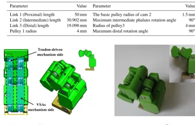
Table 3.Parameters of design cam 2 and cam 4.
Parameter Value Parameter Value
Link 1 (Proximal) length 50 mm The basic pulley radius of cam 2 1.5 mm Link 2 (Intermediate) length 30.902 mm Maximum intermediate phalanx rotation angle 90◦
Link 3 (Distal) length 19.098 mm Radius of pulley3 4 mm
Pulley 1 radius 4 mm Maximum distal rotation angle 90◦
Figure 8.CPRF mechanical parts(a)CAD drawing(b)produced Prototype.
WhereRFSRandGFSRare the resistance and the
conduc-tance of FSR sensor, respectively. In the designed electronic circuit of the CPRF,Vcc=5 V andR=10 k. Converting
the signal of sensors to force in Newton (N) unit is obtained using Eq. (42d), the relation between force and resistance mentioned in the datasheet of the used sensor i.e. FSR 400 series sensor, and the following algorithm;
Step (1): Read the signal of FSR sensor
Step (2): Calculate the conductance from Eq. (42d) Step (3): Check the conductance to see if it is less
than or equal 1000
Step (4): Not valid? Calculate the force as: Force=GFSR−1000
30 N
Step (5): Valid? Calculate the force as: Force=GFSR 80 N
Step (6): End
The grasped object is detected when the signal of the sen-sor is above zero. Control servo motors are done by connect-ing signals of servo motors to the PWM on the microcon-troller board. Fig. 9b presents the overall view of the elec-tronic hardware system. A Simulink model as a software tool is built in MATLAB to read the signals of the force sen-sors and actuate the motion of the motors via computer. This MATLAB program is used to test the control algorithms and the performance of the designed finger in a realistic way.
3.2 CPRH Developing
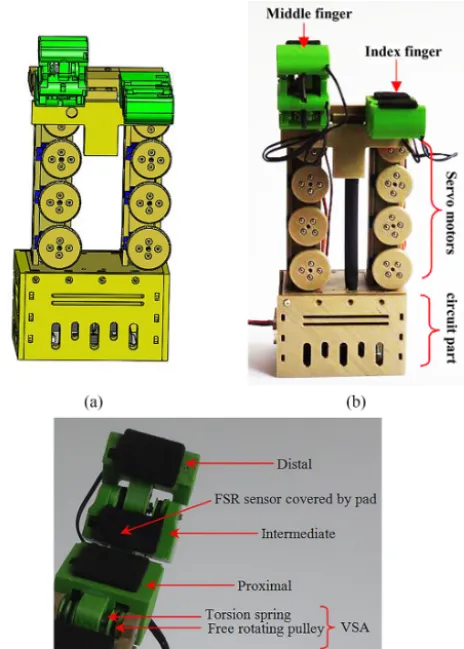
The design of the mechanical parts of the CPRH includes hand base, palm, two CPRFs, and an electronic hardware box. The hand base contains motors to actuate the motion of the CPRFs and tune VSAs. The CPRF motion is actuated by one tendon through a servo motor type (SH-0253) for closing and opening motions, the stiffness of each VSA is controlled by tendon through a servo motor type (SG90) that resulted in driving each finger by four motors. FSR sensors are cov-ered by a pad in order to assist diffusing touch across the sensor region and enhance the grasp performance due to its coefficient of friction and soft property. The final CPRH pro-totype system is manufactured as shown in Fig. 10 where all the mechanical parts of the 3-D drawing are produced by the 3-D printer.
Figure 9.CPRH System(a)Diagram of components(b)Hardware architecture of the electronic and drive system.
4 Control Algorithms
4.1 MIMO Fuzzy Controller
In the practical application of CPRF, the factors that affect the grasping are complex and involve tendon mechanism, multi-VSAs, interactional contact between the phalanges and the grasped object, response time of sensors and servo mo-tors, and CPRF dynamics. Since the majority of these fac-tors are variant with time and nonlinear, calculating the exact mathematical model of the CPRF is not easy. As a result, tra-ditional control methods such as PID method lack providing accurate grasp control. However, the fuzzy control technique can be applied to real applications dependent on knowing an intuitive realization of the best way to control the system (Passino and Yurkovich, 1997). A special MIMO fuzzy con-troller is designed and applied to the CPRF control system shown in Fig. 13. The controller is a MIMO that sinks the in-dication from the force sensors, assesses them, and produces a conclusion according to its predefined rules to formulate output torque values in each VSA.
Figure 10.The prototype of robot hand (a)3-D CAD drawing (b)CPRH(c)CPRF.
Figure 11.Workspace of the designed CPRF for seven situations with 10◦step between each one.
The action of the controller is qualified by fuzzy rules with the relation of input data mapping and proposition of output, the linguistic variables are;
Figure 12.Monitoring touch performance of force signals.
Figure 13.Block diagram of the CPRF control system.
VSA_Torque 1={low, medium, high} VSA_Torque 2={low, medium, high} VSA_Torque 3={low, medium, high}
The input variables and output variables have 27 rela-tions Rij k and 27 propositionsPijk, respectively. The
rela-tions and proposirela-tions are expressed in a matrix form as shown in Fig. 14, wherei, j, k=1, . . .,3; Fi=FSR_Force i; Ti=VSA_Torque i. Fuzzy rule are defined now by IF rela-tion then proposirela-tion statements as;
IFRij kTHENPij k
The rules, there are 27 rules that determine the values of outputs, are specified according to the designed relations and proposition matrix shown in Fig. 14. To clarify the designed rules, let us assume the conditions of force sensors are;
FSR signal 1 is low, FSR signal 2 is high, FSR signal 3 is low
In this case, as shown in Fig. 14, the rule is set as;
if (FSR Force 1 is low) and (FSR Force 2 is high) and (FSR Force 3 is low) then (VSA Torque 1 is low) and (VSA Torque 2 is high) and (VSA Torque 3 is low)
Another example is assumed when the conditions of force sensors are;
FSR Force 1 is high, FSR Force 2 is low, FSR Force 3 is low
Then, as shown in Fig. 14, the rule is set to;
if (FSR Force 1 is high) and (FSR Force 2 is low) and (FSR Force 3 is low) then (VSA Torque 1 is high) and (VSA Torque 2 is low) and (VSA Torque 3 is low)
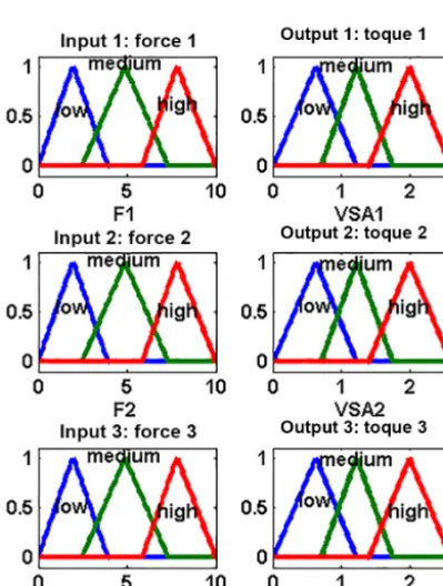
In the same way, the other rules are set according to the state of the input force sensors. The input forces of the con-troller and the output torques are decomposed into fuzzy sets (low, medium, high) by triangular membership functions of rangeha biand nucleushc di;
µF=
0 (x < a)∪(x > b)
x−a
b−a for a≤x < b
1 for b≤x < c d−x
d−c for c≤x < d
Figure 14.Fuzzy inputs and outputs(a)relations(b)Prepositions.
Figure 15.Fuzzy sets of inputs and outputs.
Matching to the range of FSR signal of 10-bit data from 0 to 1023, the domain of the input force sensor in New-ton unit is set from 0 to 10 N depending on the prop-erties of the applied sensors FSR400 series. The range of the output torque is set depending on the designed VSA. The control strategy is assumed from1θ equal 0 to 270◦ which results in changes of mean diameter and stiff-ness from (5.3 mm, 0.2144 N mm degree−1) to (4.627 mm, 0.5512 N mm degree−1) according to Eqs. (8) and (9). Hence,
the torque by VSA is supplied in joint space according to Eq. (10) from 0 to 2.5973 N mm.
The plot of the fuzzy sets is presented in Fig. 15, the fuzzy is implemented using Mamdani with the center of gravity de-fuzzification method of implication minimum operator and aggregation maximum operator. The first step of the fuzzifi-cation process is to obtain the crisp of the forces sensors and to determine how these inputs belong to the fuzzy sets. Then, the fuzzified inputs using Eq. (43) is taken and applied to the antecedents of the rules. Since our designed fuzzy controller rule has various antecedents operator, the AND or OR oper-ator is implemented to get the value of the antecedent eval-uation. Then, this value is used to the followed membership function. The fuzzy operation (OR) union maximum opera-tor is used to find the disjunction of the rule antecedents, as below;
µA∪B(x)=maximum (µA(x), µB(x),) (44)
and the fuzzy operation (AND) intersection minimum opera-tor is used to finding the conjunction of the rule antecedents, as bellow;
µA∩B(x)=minimum (µA(x), µB(x)) (45)
4.2 Optimized MIMO Fuzzy Controller
algorithm is an advanced technique for complex issues that realizes optimum value for several systems (Gen and Cheng, 1997). The tuning process of membership boundaries via genetic algorithm is performed using MATLAB. The code takes the calculated data from the designed tradition fuzzy controller Simulink model to compute the difference be-tween the VSA torques. The planning for the implemented genetic algorithm is as follows;
– Population: the generated population includes the indi-viduals which represented in our case the boundary of the input membership function as;
x
ˇ
i,jˇ
where ˇi andjˇ are the index of boundary and contact force, respectively. In the designed fuzzy controller, as shown in Fig. 15, there are three membership functions (low, medium, high) and three contact forces (Force 1, Force 2, Force 3). So,ˇi= ˇj =1,2,3 .
– Fitness function: to optimize the performance of the fuzzy controller, it is important to specify the fitness function. The aim of our fuzzy controller is to supply appropriate close values of VSA-torque during grasp-ing. Consequently, the fitness function is defined as
Fitness_Function=
absolute (Torque 1−Torque 2−Torque 3) (46)
The adjusting process of boundaries is limited by the physical properties of our force sensors and VSAs. Thus, the limits of the applied genetic algorithm are set as follows;
Forcej, <ˇ 10,
Torquej <ˇ 2.5973,
– Genetic algorithm parameters: The genetic algorithm is set with the following values; size of population: 90 and number of generation: 40.
The result of the optimization process of the fuzzy con-troller in term of the new triangular membership parameters is shown in Fig. 16.
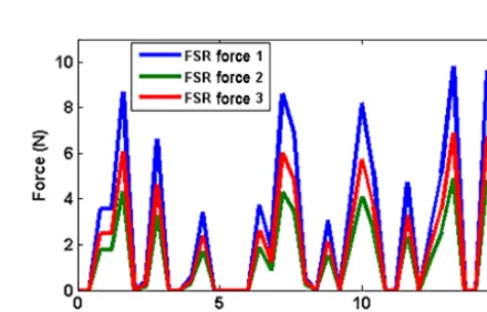
To explain the advancement of the optimized fuzzy con-troller, the traditional fuzzy controller explained in Sect. 4.1 and optimized fuzzy controller are tested under the contact force touching scenario. The simulation time is set to 15 s. Note that the performance of the controllers is examined un-der contact forces shown in Fig. 17. Results are shown in Fig. 18 with the VSA-torque compared between Fuzzy and optimized fizzy controllers.
To further explain the distinction between the two con-trollers, the absolute difference between the VSA torques in
Figure 16.Optimized Fuzzy sets of inputs.
Figure 17.Contact force on phalanges scenario.
each controller of data presented in Fig. 18 is plotted together in Fig. 19. It can be noticed that there is a distinctive dif-ference between the obtained VSA-torques of the two fuzzy controllers. The optimized fuzzy controller has preferred the values of VSA-torques. In turn, the CPRF grasping is en-hanced with an appropriate controller in addition to the func-tionality of the proposed adjustable stiffness tendon-driven mechanism.
4.3 Operation Control
pha-Figure 18.Traditional optimized VSA-torques.
Figure 19.The difference between VSA-torques.
lanx which is directly in connection with that VSA. For ex-ample, according to test 2 and test 3, the finger stopped its motion when the force F1 reached the threshold value. In the same time, the torque of VSA1 increased due to increasing the force on proximal phalanx which is directly connected to it.
5 Experimental results
The performance of the developed CPRF prototype is exam-ined in this section. In specific, the grasping ability is tested with different objects as shown in Fig. 21. Taking into
con-Figure 20.Program flowchart of the control algorithms for each finger.
Table 4.Process parameters of testing the control algorithm.
Tendon Test F1 F2 F3 TVSA1 TVSA2 TVSA3 actuating
No. (N) F(N) (N) (N mm) (N mm) (N mm) status 1 0 0 0 0.6123 0.6123 0.6123 On 2 1.5 1.5 1.5 0.617 0.617 0.629 On 3 2 1.5 1.5 0.82 0.62 0.631 Off 4 3 7 9 0.7623 1.765 1.997 Off
5 8 7 6 1.886 1.777 1.345 Off
6 10 6 2 2 1.997 0.7741 Off
sideration that CPRF grasping is characterized by its func-tionality to grasp different objects of various surfaces shape and type (soft or hard), sizes, and weights.
Figure 21.Hand grasping by CPRF.
Figure 22.CPRF system response to the applied control algorithms.
torque increased in cases where there was more load exerted on the phalanx. This is a very important property to support an extra torque in order to prevent the phalanx from moving in the opposite direction, which leads to losing the object. Moreover, the practice results showed that the finger can hold an object firmly even though the hand gripper was moved, the weight of the object was relatively heavy, or an external ef-fect tried to remove the grasped object from the hand (see hyperlink of “Movie 2 CPRF” in the Appendix).
6 Discussion
These results indicate beneficial techniques for sensing the grasped objects utilizing only low-cost FSR sensors. The suggested mechanism of VSAs let the ability to improve and adjust low grasped forces of the tendon-driven mechanism. In addition, adjusting the stiffness of VSAs via tendons by motors in the fixed part under the palm rather than the joints
time 5.7 s, the ball is pinched by all phalanges. Meanwhile, the VSAs torques are updated their values according to the sensed forces to support the firm grasping. The VSAs torques were close to each other thanks to the optimized fuzzy con-troller.
7 Conclusion
VSAs are of distinguished significance for their rules in im-proving the problem of low grasped forces of the tendon-driven mechanism in fingers. A firm grasping with mus-cle type joints is established in this paper by incorporat-ing the tendon-driven mechanism with VSAs in the sug-gested mechanism. The force isotropy property is obtained by introducing a mathematical procedure to obtain the non-linear cam/pulleys transmission. The suggested sensorimo-tor system has provided the advantage that grasping can be reached with low-cost force sensing and actuating compo-nents. A fuzzy logic controller has been suggested to con-trol the VSAs torques according to the contact force val-ues. For the optimized fuzzy logic controller, GA enabled the VSAs. This to support appropriate torque values in joint
space. In addition, the suggested control algorithm has or-ganized the operation of the finger during the planning and holding tasks to grasp objects firmly and in a safe manner. algorithm has regulated the movement of the finger in the planning stage and activated the fuzzy controller to support appropriate VSA torque in the holding stage. The experi-mental results have proved the ability of the tendon-driven cam/pulleys mechanism to grasp objects successfully in a firm manner without needing a description of any informa-tion from the grasped object. In addiinforma-tion, the experimental results have proved the function of the VSAs to hold relative heavy objects and overcome interferences by increasing the grasp forces. This finger prototype is proposed as an initial step, as a future work, it is recommended to improve hand size and the number of fingers as a second step such that it can be closer to a real human hand.
Appendix A: Index to video records
Video records of this article can be reached online according to the mentioned hyperlinks in Table 5.
Table A1.Index to video records.
Name Type Details
Author contributions. IAD, AK, and SK designed the mecha-tronic system of the robot finger. IAD developed the control algo-rithms and code. IAD, AK, and SK carried the experiments out. IAD prepared the manuscript with advices from AK and SK. AK and SK revised the manuscript.
Competing interests. The authors declare that they have no conflict of interest.
Edited by: Lionel Birglen
Reviewed by: four anonymous referees
References
Albu-Schäffer, A., Wolf, S., Eiberger, O., Haddadin, S., Pe-tit, F., and Chalon, M.: Dynamic modelling and con-trol of variable stiffness actuators, in: Proceedings 2010 IEEE International Conference on Robotics and Automa-tion, 3–7 May 2010, Anchorage, AK, USA, 2155–2162, https://doi.org/10.1109/ROBOT.2010.5509850, 2010.
Ask, T.: Engineering for Industrial Designers and Inventors: Fun-damentals for Designers of Wonderful, O’Reilly Media, Se-bastopol, CA, USA, 2016.
Aukes, D., Heyneman, B., Duchaine, V., and Cutkosky, M. R.: Varying spring preloads to select grasp strategies in an adaptive hand, in: Proceedings 2011 IEEE/RSJ Interna-tional Conference on Intelligent Robots and Systems, 25– 30 September 2011, San Francisco, CA, USA, 1373–1379, https://doi.org/10.1109/IROS.2011.6095078, 2011.
Birglen, L. and Gosselin, C. M.: Fuzzy Enhanced Control of an Un-deractuated Finger Using Tactile and Position Sensors, in: Pro-ceedings of the 2005 IEEE International Conference on Robotics and Automation, 18–22 April 2005, Barcelona, Spain, 2320– 2325, https://doi.org/10.1109/ROBOT.2005.1570459, 2005. Birglen, L., Laliberté T., and Gosselin, M.: Underactuated Robotic
Hands, Springer, Berlin, Heidelberg, Germany, 2008.
Boucher, J. and Birglen, L.: Performance Augmentation of Un-deractuated Fingers’ Grasps Using Multiple Drive Actua-tion, ASME. J. Mechanisms Robotics, 9, 041003–041003-10, https://doi.org/10.1115/1.4036220, 2017.
Braun, D., Howard, M., and Vijayakumar, S.: Optimal variable stiff-ness control: formulation and application to explosive movement tasks, Auton. Robot., 33, 237–253, 2012.
Bundhoo, V., Haslam, E., Birch, B., and Park, E. J.: A shape mem-ory alloy-based tendon-driven actuation system for biomimetic artificial fingers, part I: Design and evaluation, Robotica, 27, 131–146, https://doi.org/10.1017/S026357470800458X, 2009. Buss, M., Hashimoto, H., and Moore, J. B.: Dextrous Hand
Grasp-ing Force Optimization, IEEE Transactions on Robotics and Au-tomation, 12, 406–418, 1996.
Ciocarlie, M., Hicks, F. M., and Stanford, S.: Kinetic and dimen-sional optimization for a tendon-driven gripper, in: Proceed-ing 2013 IEEE International Conference on Robotics and Au-tomation, 6–10 May 2013, Karlsruhe, Germany, 2751–2758, https://doi.org/10.1109/ICRA.2013.6630956, 2013.
Dandash, G., Rizk, R., Krut, S., and Dombre, E.: A pseudo-isotropic three phalanxes under-actuated finger, IFToMM’2011:
13th World Congress in Mechanism and Machine Science, June 2011, Guanajuato, Mexico, 1–8, 2011.
Fumagalli, M., Barrett, E., Stramigioli, S., and Carloni,R.: Analysis of an underactuated robotic finger with vari-able pinch and closure grasp stiffness, 2016 IEEE Inter-national Conference on Advanced Intelligent Mechatronics (AIM), 12–15 July 2016, Banff, AB, Canada, 365–370, https://doi.org/10.1109/AIM.2016.7576794, 2016.
Gen, M. and Cheng, R.: Genetic Algorithms and Engineering De-sign, Wiley, New York, USA, 1997.
Hristu, J., Babb, J., Singh, H., and Gottschlich, S.: Position and force control of a multifingered hand: a comparison of fuzzy logic to traditional PID control, in: Proceeding of the IEEE/RSJ/GI International Conference on Intelligent Robots and Systems, 12–16 September 1994, Munich, Germany, 2, 1391– 1398, https://doi.org/10.1109/IROS.1994.407502, 1994. In, H. and Cho, K. J.: Concept of variable transmission for
ten-don driven mechanism, in: Proceeding 2013 10th International Conference on Ubiquitous Robots and Ambient Intelligence (URAI), 30 October–2 November 2013, Jeju, South Korea, 15– 16, https://doi.org/10.1109/URAI.2013.6677459, 2013. Kino, H., Okamura, N., and Yabe, S.: Basic characteristics of
tendon-driven manipulator using belt pulleys, In: Proceed-ing 2004 IEEE/RSJ International Conference on Intelligent Robots and Systems (IROS) (IEEE Cat. No.04CH37566), 28 September–2 October 2004, Sendai, Japan, 2, 1287–1292, https://doi.org/10.1109/IROS.2004.1389573, 2004.
Krut, S.: A Force-Isotropic Underactuated Finger, in: Proceeding of the 2005 IEEE International Conference on Robotics and Automation, 18–22 April 2005, Barcelona, Spain, 2314–2319, https://doi.org/10.1109/ROBOT.2005.1570458, 2005.
Kuo, P. H., DeBacker, J., and Deshpande, A. D.: Design of robotic fingers with human-like passive parallel compliance, in: Proceed-ing 2015 IEEE International Conference on Robotics and Au-tomation (ICRA), 26–30 May 2015, Seattle, WA, USA, 2562– 2567, https://doi.org/10.1109/ICRA.2015.7139543, 2015. Ozawa, R., Hashirii, K., and Kobayashi, H.: Design and
con-trol of underactuated tendon-driven mechanisms, in: Pro-ceeding of 2009 IEEE International Conference on Robotics and Automation, 12–17 May 2009, Kobe, Japan, 1522–1527, https://doi.org/10.1109/ROBOT.2009.5152222, 2009.
Ozawa, R., Kobayashi, H., and Hashirii, K.: Analysis, Classification, and Design of Tendon-Driven Mecha-nisms, IEEE Transactions on Robotics, 30, 396–410, https://doi.org/10.1109/TRO.2013.2287976, 2014.
Palli, G. and Melchiorri, C.: Interaction Force Control of Robots with Variable Stiffness Actuation, 18th IFAC World Congress, 44, 13504–13509, 2011.
Passino, K. M. and Yurkovich, S.: Fuzzy Control, Addison-Wesley Longman Publishing Co., Redwood City, CA, USA, 1997. Pololu Force Sensing Resistor: Pololu robotics and electronics,
available at: https://www.pololu.com, last access: 25 February 2018.
Rizk, R., Krut, S., and Dombre, E.: Grasp-stability analysis of a two-phalanx isotropic underactuated finger, in: Proceeding 2007 IEEE/RSJ International Conference on Intelligent Robots and Systems, 29 October–2 November 2007, San Diego, CA, USA, 3289–3294, https://doi.org/10.1109/IROS.2007.4399169, 2007. Rodríguez, N.: Optimal design of driving mechanism in a 1-DOF
anthropomorphic finger, Mech. Mach. Theory, 41, 897–911, https://doi.org/10.1016/j.mechmachtheory.2006.03.016, 2006. Shigley, J. and Mischke, C.: Standard handbook of machine design,
McGraw-Hill STANDARD HANDBOOKS, Ney York, USA, 2004.