Volume 2009, Article ID 658047,9pages doi:10.1155/2009/658047
Research Article
A Novel Image Data Hiding Scheme with Diamond Encoding
Ruey-Ming Chao,
1Hsien-Chu Wu,
2Chih-Chiang Lee,
3and Yen-Ping Chu
41Graduate Institute of Information and Social Science, National United University, 1 Lienda, Miaoli 360, Taiwan 2Graduate School of Computer Science and Information Technology, National Taichung Institute of Technology,
129, Section 3, San Min Road, Taichung City 404, Taiwan
3Department of Computer Science and Engineering, National Chung Hsing University, 250, Kuo Kuang Road,
Taichung City 402, Taiwan
4Department of Computer Science and Information Engineering, Tunghai University, 181, Section 3, Taichung Port Road,
Situn District, Taichung City 407, Taiwan
Correspondence should be addressed to Hsien-Chu Wu,[email protected] Received 1 August 2008; Revised 29 November 2008; Accepted 20 March 2009 Recommended by Andreas Westfeld
A novel data hiding scheme in digital images with the diamond encoding by pixel value adjustment is proposed. The proposed method is the extension of the exploiting modification direction (EMD) embedding scheme. First, the process of embedding partitions the cover image into nonoverlapping blocks of two consecutive pixels and transforms the secret messages to a series of
k-ary digits. For each block, the diamond encoding technique is applied to calculate the diamond characteristic value, and one secretk-ary digit is concealed into the diamond characteristic value. The diamond characteristic value is modified to secret digit and it can be obtained by adjusting pixel values in a block. This scheme is designed in such a way that the distortion of each block after diamond encoding is never out of the embedding parameterk, and the block capacity is equal to log2(2k2+ 2k+ 1). The
diamond encoding provides an easy way to produce a more perceptible result than those yielded by simple least-significant-bit substitution methods. The embedded secret data can be extracted without the original cover image. Experimental results have demonstrated that the proposed method is capable of hiding more secret data while keeping the stego-image quality degradation imperceptible.
Copyright © 2009 Ruey-Ming Chao et al. This is an open access article distributed under the Creative Commons Attribution License, which permits unrestricted use, distribution, and reproduction in any medium, provided the original work is properly cited.
1. Introduction
In recent years, communication security over the Internet is becoming more and more important because the multimedia and network are widely developed. Two fields of research have been proposed to enhance the communication security: cryptography and information hiding. Although they are both applied to the protection of secret message, the major difference is the appearance of the transmitted data. The cryptography methods, such as DES and RSA, referred almost exclusively to encryption which is the process of con-verting ordinary information (plaintext) into unintelligible gibberish (cipher-text). After data encryption, the secret data appears to be a total chaos of seemingly meaningless bits. However, the existence of the transmitted secret message can be detected. Because it does not conceal the fact that there is an important message, the encrypted message could
most insignificant parts of the cover image. It attempts to establish covert communication between trusting parties and prevent malicious interceptors or attackers from discovering the existence of the hidden message in the stego-image.
Many approaches of information hiding have been pro-posed for different applications, such as copyright protection [4], secret transmission [5], tampering detection [6], and image authentication [7]. The most well-known data hiding scheme is the least significant bits (LSBs) substitution method. This method embeds fixed-length secret bits into the least significant bits of pixels by directly replacing the LSBs of cover image with the secret message bits. The LSBs approach assumes that the base of the hidden numerical data is a whole power of 2 (e.g., 1-bit LSB means the hidden number is treated as a binary number because 21 = 2,
2-bit LSB means the hidden number is treated as a number of base 22 = 4, etc.). Although this method is simple, it
generally effects noticeable distortion when the number of embedded bits for each pixel exceeds three. Several methods have been proposed to reduce the distortion induced by LSBs substitution. OPAP [8] scheme searches the minimal distortion value which LSBs equal the embedded bits and replaces stego-pixel value with it. Another way of improving LSBs scheme is to reduce the amount of alterations necessary to be introduced into the cover image for data hiding when the number of secret bits is significantly less than that of available cover pixels. The method proposed by Tseng et al. [9] can conceal as many as log2(mn+ 1) bits of data in a binary image block sizedm×nby changing, at most, two bits in the block. Matrix encoding [10], on the other hand, uses less than one change of the least significant bit in average to embedwbits into 2w−1 cover pixels. Recently, Wu and Tsai [11] proposed a “pixel value differencing” (PVD) method that computes the difference value between two neighboring pixels to determine how many secret bits should be embedded into a cover pixel. All difference values are classified into some ranges that contain different levels of the value. In order to embed secret bits, the difference value is changed but it cannot outside the range of original difference, and the pair of original cover pixels is modified according with the new difference value. In addition, Wang et al. [12] presented an improvement of pixel value differencing scheme where the secret data is hidden in pixel difference with a modulus function. So the alteration caused by the hiding of the secret data is greatly reduced. The proposed method is the extension of the exploiting modification direction (EMD) embedding scheme [13]. The EMD embedding scheme hides each (2n+ 1)-ary notational secret digit into n cover pixels, and only one pixel value increases or decreases by 1 at most.
In this paper, an efficient data hiding method is proposed for gray-scale images by utilizing the diamond encoding concept. We first transform the secret data into a sequence of digits, and the cover image is partitioned into nonoverlap-ping blocks of two consecutive pixels. The diamond encoding method produces a diamond characteristic value (DCV) of the pixel-pair block, and the DCV is revised as the embedded secret digit after data embedding procedure. For each block, the diamond encoding technique addresses the
minimal changes of two pixel values under the embedding parameter k. In other words, the difference between the cover-block and the stego-block is never more than k, and the embedding capacity of a block equals log2(2k2 +
2k + 1). The diamond encoding technique minimizes the distortion after the DCV alteration to perform better visual quality. Experimental results have demonstrated that the proposed method is capable of hiding more secret data while maintaining imperceptible stego-image quality degradation. The remainder of this paper is organized as in the fol-lowing sections. We will describe the exploiting modification direction scheme first in Section 2. Section 3 will present the concept of diamond encoding method. InSection 4, the framework of the proposed scheme will be shown in detail. InSection 5, we will analyze the new scheme and compare it with some well-celebrated schemes in terms of payload and stego-image quality, respectively. Finally, a brief conclusion will be given inSection 6.
2. Review of the Exploiting Modification
Direction Embedding Scheme
The proposed method is the extension of the exploiting modification direction (EMD) embedding scheme [13]. The main idea of the EMD embedding scheme is that each (2n+ 1)-ary notational secret digit is carried by n cover pixels, and only one pixel value increases or decreases by 1 at most. For each block ofncover pixels, there are 2npossible states of only one pixel value plus 1 or minus 1. The 2n states of alteration plus the case in which no pixel is modified form (2n+ 1) different cases. Therefore, the (2n+ 1)-ary notational secret digit is embedded into the cover pixels by changing the state. Before the data embedding procedure, the preprocess can convert the secret data into sequences of digits with (2n+ 1)-ary notational representation. For the simplest case of n = 2, the secret data stream S(2)can
be expressed asS(5)whereS(d)denotes thed-ary notational
system representation of secret data streamS. Thus, the 5-ary digits can conceal into blocks of two cover pixels by modifying at most one pixel value. Denote the gray values of a block of two cover pixels asp1andp2, and the extraction
function f is defined as a weighted sum modulo 5:
fp1,p2
=
⎡ ⎣2
i=1
pi×i
⎤⎦
mod 5. (1)
Suppose that the transformed 5-ary secret digitsdesired to be embedded into the cover pixels p1 andp2. According to
the secret digit, the embedding process can be classified into 5 conditions.
Condition 1. If (s−f(p1,p2)) mod 5=0:
No modification is needed because the extraction func-tion f can decrypt the correct secret data.
Condition 2. If (s−f(p1,p2)) mod 5=1:
Increase the pixel valuep1by 1.
Condition 3. If (s−f(p1,p2)) mod 5=2:
p,q–1
p−1,q p+1,q p,q+1
p,q
(a)S1(p,q)
p,q−2
p–1,q–1 p,q–1 p+1,q–1
p–2,q p−1,q p+1,q p+2,q p–1,q+1 p,q+1 p+1,q+1
p,q+2 p,q
(b)S2(p,q)
Figure 1: (a) Diamond encoding patterns withk = 1 and (b) diamond encoding patterns withk=2.
Condition 4. If (s−f(p1,p2)) mod 5=3:
Decrease the pixel valuep2by 1.
Condition 5. If (s−f(p1,p2)) mod 5=4:
Decrease the pixel valuep1by 1.
By the above operations, the stego-pixel value of the block is obtained. The extraction function f(p1,p2) is equal
to the secret digit s. For example, the secret data stream 1010(2) can be expressed as 20(5). Consider an original
pixel group (55, 57, 53, 60), and the extraction functions f(55, 57) = 4 and f(53, 60) = 3 are calculated by (1). We compute, above equation (2− f(55, 57)) mod 5=(2− 4) mod 5=(−2) mod 5=3. Then, the first pixel pair located into Condition 4, and the pixel value 57 must decrease by 1. Similarly, the second pixel pair located into Condition 3 by the equation (0− f(53, 60)) mod 5 = (0−3) mod 5 = (−3) mod 5 = 2. The fourth pixel value must increase by 1. Finally, we can get the stego-group (55, 56, 53, 61) by modifying at most one value of two pixel values. In the extraction phase, the extraction function f(55, 56)=2 and f(53, 61) = 0 can be extracted directly, and data stream 1010(2)is decrypted by transforming the secret digit 20(5).
3. The Diamond Encoding
In this section, we shall introduce the general operation of the diamond encoding technique. The EMD scheme embeds (2n + 1)-ary digit into n cover pixels, but the diamond encoding scheme can conceal (2k2+ 2k+ 1)-ary digit into
a cover pixel pair wherekis the embedding parameter. The detail of this scheme is described as follows.
Assume thata,b, p, andq are pixel values, andk is a positive integer. The neighborhood setSk(p,q) represents the set that contains all the vectors (a,b) with the distance to vector (p,q) smaller than k, and Sk(p,q) is defined as the following form:
Sk
p,q= (a,b)|p−a+q−b≤k. (2)
Let the absolute value|Sk|denote the number of elements of the setSk, and each member inSk is called neighboring vector of (p,q). We calculate the value of|Sk|to obtain the embedding base and embedded base with a parameterk. The examples ofSkare illustrated inFigure 1, and we can obtain |S1| = 5,|S2| = 13,|S3| = 25, and so on. Moreover, we
compute the|Sk|value by the following equation, and the embedding base equals to the value of|Sk|,
|Sk| = ⎛ ⎝k
i=0
(2i+ 1) ⎞ ⎠+
⎛ ⎝k
i=1
(2i−1) ⎞ ⎠
=1 + ⎛ ⎝k
i=1
(2i+ 1 ) ⎞ ⎠+
⎛ ⎝k
i=1
2i−1 ⎞ ⎠
=1 + ⎛ ⎝k
i=1
(2i+ 1) + (2i−1) ⎞ ⎠
=1 + ⎛ ⎝k
i=1
4i
⎞ ⎠
=1 +k(k+ 1)
2 ×4
=1 + 2k(k+ 1) =2k2+ 2k+ 1.
(3)
The proposed diamond encoding method uses a dia-mond function f to compute the diamond characteristic value (DCV) in embedding and extraction procedures. The DCV of two pixel valuespandqcan be defined as follows:
fp,q=(2k+ 1)×p+qmodl, (4)
where l is the absolute value of Sk. The DCV have two important properties: (1) the DCV of the vector (p,q) is the member of Sk belongs to {0, 1, 2,. . .,l −1} and (2) any two DCVs of vectors in Sk(p,q) are distinct. Assume that Ek represents the embedded digit and Ek belongs to {0, 1, 2,. . .,l−1}. For secret data embedding, we replace the DCV of the vector (p,q) with the embedded secret digit. Therefore, the modulus distance between f(p,q) andSk is dk= f(p,q)−Ekmodl. For eachk, we can design a distance pattern Dk to search which neighboring pixel owns the modulus distancedk, and differentDkare shown inFigure 2. Then, the vector (p,q) is replaced with the neighboring vector (p,q) by dk. The vector (p,q) is the member of Sk(p,q) and the DCV of (p,q) equals to the embedded secret digit Ek. The vector (p,q) can extract the correct secret digit by (5):
fp,q=(2k+ 1)×p+qmodl. (5)
The diamond encoding scheme promises that the distortion of vector (p,q) is no more thankafter embedding a secret digit Ek. Therefore, this minimal distortion scheme can be employed to embed large amount of data.
4. The Proposed Method
4 2 0 3
1
(a)D1(p,q)
11 7 12 4 3 8 0 5 10
9 1 6 2
(b)D2(p,q)
22
16 23 5 10 17 24 6
4 21
12 19 1
20 9
3 18
11 0 7 14 2
15
8
13
(c)D3(p,q)
Figure2: Diamond encoding patternsDk withk=1,k =2, and k=3.
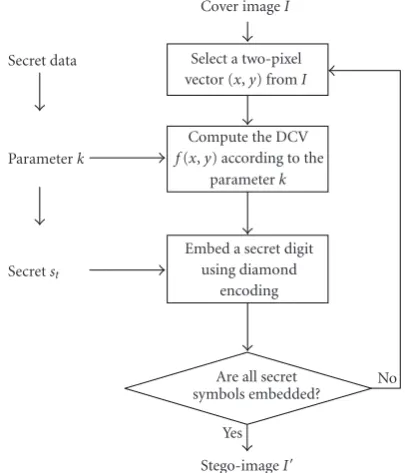
Cover imageI
Stego-imageI
Secretst Parameterk
Secret data
Yes
No Select a two-pixel
vector (x,y) fromI
Compute the DCV
f(x,y) according to the parameterk
Embed a secret digit using diamond
encoding
Are all secret symbols embedded?
Figure3: Data embedding process.
In our method, the embedding parameter kis determined firstly, and the diamond encoding with parameter k can conceal secret data into the cover image. The detailed steps of the proposed scheme are discussed in the following subsections.
4.1. Embedding Procedure.
Step 1. To begin with, according to the secret data size, a parameter kis selected, and we transform secret data into diamond encoding digits. Assume that the secret data size is s, and then the embedding parameter k is determined by finding the minimal positive integer that satisfies the following inequality:
m×n
2
log22k2+ 2k+ 1 ≥s. (6)
Stego-imageI
Parameterk
Secret data Yes No
Select a two-pixel vector (x,y) fromI
Compute the DCV
f(x,y) according to the parameterk
Secret symbols
Are all secret symbols extracted?
Figure4: Data extraction process.
Figure5: Sequence of nonoverlapping consecutive two-pixel blocks is constructed in a cover image.
Set the embedding basel = 2k2+ 2k+ 1. Then, the secret
message is regarded as a sequence of digits inl-ary notational system.
Step 2. In the data embedding procedure, the original image is segmented into a number of nonoverlapping two-pixel blocks. Then, we can select each block from top-down and left-right in turn for data embedding process. The block vector (x,y) is defined asx=I(2t) andy=I(2t+ 1) whereI is the cover image sizedm×n, andtis the block index. The block construction of the proposed scheme is illustrated by Figure 5. The embedded secret data bit stream is transformed into l-ary digit sequence. Moreover, the embedded secret digitst is obtained from thetth index of the sequence of l-ary digits.
Step 3. Compute the DCV of two pixel valuesxandyby (4)
Step 4. The new stego-image pixel pair can be calculated by replacing f(x,y) withst.The used equation is shown as follows:
dt=
st−f
x,ymodl. (8)
The symbol dt shows the modulus distance between the st and f(x,y). By applying the distance dt, the stego-pixel values x and y can be found in Dk such that the DCV is replaced with st. However, in this step, the overflow or underflow problems might be occurred; that is, the stego-pixel value x or y might go beyond 255 or below 0. If it happens, the next step, namelyStep 5, has to be processed; otherwise,Step 5has to be skipped, and the data embedding procedure is finished.
Step 5. When one stego-pixel value has the overflow or underflow problem, the critical vector (x,y) has to be adjusted to the appropriate value. The adjustment rules are defined as follows:
(1) ifx>255,x=x−l; (2) ifx<0,x=x+l; (3) ify>255,x=x−l; (4) ify<0,y=y+l.
From the above rules, it can be observed that the overflow/underflow problem is solved and the DCV also has the same value. After all, we take the next pixel pair from the cover image and repeat Steps2–5. Repeat until all the secret data have been concealed. Then we collect all stego-pixel values to form the stego-imageI. The embedding parameter khas to transmit to the receiver in order to extract data.
4.2. Extraction Procedure. Here are the steps to extract the secret data from the stego-imageI and the detailed secret data extraction is described as follows.
Step 1. To begin with, in the data extraction procedure, the original image is segmented into a number of nonoverlap-ping two-pixel blocks. Then, we can select each block from top-down and left-right in turn for data extraction process. The block vector (x,y) is defined asx = I(2t) andy = I(2t+ 1). The block construction of the proposed scheme is illustrated byFigure 2.
Step 2. According to the parameterk, set the embedding base l=2k2+ 2k+ 1. For each stego-pixel pairpandq, the DCV
of (x,y) is obtained from (5):
fx,y=(2k+ 1)×x+ymodl. (9)
Therefore, the secret digit st is obtained by the DCV of (x,y).
Step 3. Take the next pixel pair from the stego-image and repeat Steps1and2. The same thing goes on and on until all secret digits have been extracted for each block with indext.
Step 4. Finally, the secret data can be obtained by transform-ing the secret symbols to binary bits with base 2.
Here is an example to describe how the proposed algo-rithm actually works. Assume that the embedding parameter k = 2 and l = 13. Suppose we have pixel pairs x = 20 andy=31 and we use (4) to calculate DCV by computing f(20, 31) = (20×5 + 31) mod 13 = 1. Now let us take st =11(13)as the embedded secret digit, and we can obtain
the modulus distancedt=11−1 mod 13=10 by computing (8). Then, we searchD2(20, 31) which is shown inFigure 2
and obtain the neighboring vector (22, 31) locating in set S2(20, 31) and dk = 10. Therefore, the values of pixel pair (20, 31) are replaced with (22, 31). In the secret data extraction phase, the stego-pixel pairsx =22 and y =31 can be used to compute the DCV by f(22, 31)= 22×5 + 28 mod 13=11. Finally, the secret digitstis obtained.
5. Experimental Results and Analysis
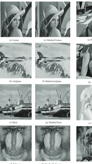
This section presents and analyzes the experimental results by using the proposed method. To evaluate the performance of our new scheme, in our experiments, we have used about 1000 images with size 512 ×512. Our evaluation starts with the eight well-known images Lenna, Airplane, Boat, Baboon, Barbara, Pepper, Tiffany, and Zelda which are shown in Figures6(a)–6(d) and7(a)–7(d). Our experiments conclude visual quality, RS attack, PVD histogram, large-scale experiment, and ROC curves. The secret messages in our experiments were generated by a pseudorandom number generator with identical probabilities for bits “1” and “0.” Figures6(e)–6(g) and7(e)–7(g) are the stego-images produced by the proposed scheme where the embedding parameterkwas set to be 6. The generated stego-images show that they contain no artifacts that can be identified by human eyes.
In the proposed algorithm, the length of hidden messages decides the embedding parameterk.However, the parameter k plays a dominant role in deciding the payload and the stego-image quality for each image. We have also designed experiments, where the “Lenna” test image was used to investigate how the proposed scheme would perform at different parameterkand the results are shown inTable 1. The embedding capacity or payload size is measured by the number of embedded bits per pixel (bpp). In the proposed method, an embedded secret digit is an l-ary data which represents log2(2k2+ 2k+ 1) bits and the payloadPcan be
computed by the following equation:
P=
log22k2+ 2k+ 1
2 . (10)
In our experiments, the quality of the stego-image is measured by the peak signal-to-noise ratio (PSNR). The PSNR is the most popular criterion to measure the distortion between the cover image and stego-image. It is defined as follows:
PSNR=10×log10
2552 MSE
(a) Lenna (e) Marked Lenna
(b) Airplane (f) Marked airplane
(c) Boat (g) Marked boat
(d) Baboon (h) Marked baboon
Figure6: Test images (a)–(d) and stego-images (e)–(h).
where MSE is the mean square error between the cover image and stego-image:
MSE= 1
m×n
m
i=1
n
j=1
[I(i,j)−I(i,j)]2. (12)
Here, the symbolsI(i,j) andI(i,j) represent the pixel values of the cover image and stego-image in the position (i,j),
(a) Barbara (e) Marked Barbara
(b) Pepper (f) Marked pepper
(c) Tiffany (g) Marked Tiffany
(d) Zelda (h) Marked Zelda
Figure7: Test images (a)–(d) and stego-images (e)–(h).
respectively, and mandnare the width and height of the original image.
Table1: Results of the proposed scheme with different parameter
k.
Parameterk |Sk| Overflow/underflow Payload PSNR (number of pixels) (bpp) (dB)
1 5 0 1.16 52.1
2 13 0 1.85 47.8
3 25 0 2.32 45.0
4 41 0 2.68 42.9
Table2: Comparison results of PSNR among LSB, OPAP, PVD, M-PVD and our scheme on various test images with embedding payload=300 000 bits (1.14 bpp).
Test images LSB OPAP PVD M-PVD Our scheme (k=1)
Lenna 49.5 50.1 46.2 49.6 52.1
Airplane 49.5 50.0 46.1 49.5 52.0
Boat 49.5 50.1 46.1 49.4 52.1
Baboon 49.5 50.1 46.2 49.4 52.0
Barbara 49.5 50.1 46.1 49.5 52.1
Pepper 49.5 50.1 46.2 49.6 52.0
Tiffany 49.4 50.0 46.1 49.7 52.1
Zelda 49.4 50.1 46.2 49.5 52.1
in fourth and fifth columns ofTable 1by (10)–(12). There-fore, human eyes cannot discover the difference between cover image and stego-image.
We compare our scheme with other existing well-known data hiding methods. The results of embedding 30 000 bits (1.14 bpp) and 60 000 bits (2.28 bpp) secret data into the test cover images are listed in Tables2 and3. Referring to Tables 2 and3, the sixth column is our proposed scheme with the diamond encoding; the column labeled LSB is the simple LSB substitution method; the column labeled OPAP is the optimal pixel adjustment LSB method [8]; the column labeled PVD is the pixel value differencing method [11]; the column labeled M-PVD is the modulus PVD method [12] (the range table of PVD and M-PVD in Tables2 and 3 are [4 4 8 8 8 16 16 32 32 64 64] and [16 16 32 64 128], resp.). For these methods, the PSNR value is employed to compare the quality of stego-images under the same embedding payload. We can see that the proposed scheme with the diamond encoding has the least distortion of all the methods tested.
In addition, the proposed scheme is secure against the well-known steganalysis likeRSdetection attack [14] or PVD histogram analysis [15]. TheRSdetection method which is proposed by Fridrich et al. can directly detect the existence of hidden data in a stego-image without perceptual analysis. By a flipping function and the maskM, they use the statistical method to classify each pixel into three groups: the regular group Rm, the singular group Sm, and the unusable group Um. Similarly, the statistical method also can classify each pixel into three groups with the inverse mask –M: R−m, S−m andU−m. The stego-image will pass the RS detection method whenRm ∼= Sm andR−m ∼= S−m. On the contrary,
Table3: Comparison results of PSNR of LSB, OPAP, PVD, M-PVD and our scheme on various test images with embedding payload= 600 000 bits (2.28 bpp).
Test images LSB OPAP PVD M-PVD Our scheme (k=3)
Lenna 42.3 45.7 37.5 40.6 46.3
Airplane 42.4 45.3 37.4 40.4 46.7
Boat 42.3 45.4 37.0 40.2 46.3
Baboon 42.5 45.3 37.1 40.3 46.3
Barbara 42.4 45.6 37.7 40.5 46.2
Pepper 42.3 45.4 37.8 40.2 46.4
Tiffany 42.5 45.6 37.2 40.3 46.6
Zelda 42.4 45.4 37.1 40.5 46.2
the stego-image will be considered as a suspicious image which contains secret data. The RS detection results of our scheme are shown inFigure 8, where the x-axis represents the embedding rate and they-axis represents the percentage of theRm,R−m,Sm andS−mwith masksM =[0 1 1 0] and −M = [0 −1 −1 0]. Moreover, we have also tested the other stego-images proposed by our scheme and the results are the same asFigure 8. As expected, the RS attack, which is targeting LSB steganography, fails to detect the proposed scheme. InFigure 9, we can see the PVD histogram results of original image and stego-image. If the histogram does not display a smooth curve, the image will be judged as a suspicious image. According to the analysis, we can make a conclusion that the proposed scheme is secure against the RS detection attack and PVD histogram analysis.
In addition, the blind attack of steganography [16, 17] is presented in 2006 to detect hidden messages in images and uses a wavelet decomposition to build higher-order statistical model of natural images by support vec-tor machine (SVM). We have collected 1000 gray-scale natural images ( all natural images were downloaded from http://dud.inf.tu-dresden.de/∼westfeld/rsp/rsp.html.). These images include decades of digital and traditional photography and consist of a range of indoor and outdoor scenes with 512×512 pixels in size. The wavelet transform decomposes the image into subbands. Thejth order horizon-tal, vertical, and diagonal subbands are denoted ashj,vj, and dj, respectively. In this experiment, we useh1,v1,d1,h2,v2,
d2,h3,v3, andd3as the decomposition subbands. Given this
image decomposition, the statistical model is composed of the mean, variance, skewness, and kurtosis of the subband coefficients, to yield 36-dimensional statistical features.
100 90 80 70 60 50 40 30 20 10 0
Rm
Sm
R−m
S−m 0
10 20 30 40 50 60
(a)k=1
100 90 80 70 60 50 40 30 20 10 0
Rm
Sm
R−m
S−m 0
10 20 30 40 50 60
(b)k=2
Figure8: TheRS-diagram for stego-image Lenna produced by the proposed scheme. (a)k=1 (b)k=2.
50 40 30 20 10 0 −10 −20 −30 −40 −050 0.5
1 1.5 2 2.5 3 ×10⁴
(a) Original image
50 40 30 20 10 0 −10 −20 −30 −40 −050 0.5
1 1.5 2 2.5 3 3.5 4 4.5 5 ×10⁴
(b) Stego-image
Figure9: The PVD histogram for (a) original image Lenna and (b) its stego-image produced by the proposed scheme.
False set; otherwise, it belongs to True set. Similarly, if the clean image can be detected by SVM as a stego-image, it is also in False set. For each test set, the accuracy formula is shown as follows:
Classification accuracy=number of True set images number of test set images.
(13)
Then, the classification accuracy for varying parameter k in testing results is shown in Table 4. According to the steganalysis result, our scheme is hardly detected for k ≤ 4. Finally, we select the estimated embedding rate as the decision threshold and generate the receiver operating characteristic (ROC) curves shown inFigure 10.
Table4: Classification accuracy (percentage) for varying parameter
kwith linear SVM and nonlinear SVM as classification kernel.
Parameter Linear SVM Nonlinear SVM
k Stego-image Clean image Stego-image Clean image
1 11.3 89.4 13.1 90.5
2 22.7 83.6 26.3 87.3
3 30.2 79.5 35.2 85.2
4 32.7 76.8 41.3 80.5
6. Conclusions
1 0.9 0.8 0.7 0.6 0.5 0.4 0.3 0.2 0.1 0
False positive rate 0
0.1 0.2 0.3 0.4 0.5 0.6 0.7 0.8 0.9 1
Tr
u
e
p
o
si
ti
ve
ra
te
(a) Linear SVM
1 0.9 0.8 0.7 0.6 0.5 0.4 0.3 0.2 0.1 0
False positive rate 0
0.1 0.2 0.3 0.4 0.5 0.6 0.7 0.8 0.9 1
Tr
u
e
p
o
si
ti
ve
ra
te
(b) Non-linear SVM
Figure10: The ROC curves with linear SVM and nonlinear SVM as classification kernel.
hiding a secret digit into two cover pixels. It not only keeps high stego-image quality but also conceals large amount of data into cover images for secret communication. The performance of the proposed scheme proves to be better than the simple LSB method and other existing schemes in terms of payload and stego-image quality.
References
[1] F. Hartung and M. Kutter, “Multimedia watermarking tech-niques,”Proceedings of the IEEE, vol. 87, no. 7, pp. 1079–1107, 1999.
[2] L. M. Marvel, C. G. Boncelet Jr., and C. T. Retter, “Spread spectrum image steganography,”IEEE Transactions on Image Processing, vol. 8, no. 8, pp. 1075–1083, 1999.
[3] X. Zhang and S. Wang, “Steganography using multiple-base notational system and human vision sensitivity,”IEEE Signal Processing Letters, vol. 12, no. 1, pp. 67–70, 2005.
[4] S.-H. Wang and Y.-P. Lin, “Wavelet tree quantization for copyright protection watermarking,” IEEE Transactions on Image Processing, vol. 13, no. 2, pp. 154–165, 2004.
[5] D.-C. Lou and J.-L. Liu, “Steganographic method for secure communications,”Computers and Security, vol. 21, no. 5, pp. 449–460, 2002.
[6] P. L. Lin, C.-K. Hsieh, and P.-W. Huang, “A hierarchical digital watermarking method for image tamper detection and recovery,”Pattern Recognition, vol. 38, no. 12, pp. 2519–2529, 2005.
[7] P. W. Wong and N. Memon, “Secret and public key image watermarking schemes for image authentication and owner-ship verification,”IEEE Transactions on Image Processing, vol. 10, no. 10, pp. 1593–1601, 2001.
[8] C.-K. Chan and L. M. Cheng, “Hiding data in images by simple LSB substitution,”Pattern Recognition, vol. 37, no. 3, pp. 469–474, 2004.
[9] Y.-C. Tseng, Y.-Y. Chen, and H.-K. Pan, “A secure data hiding scheme for binary images,” IEEE Transactions on Communications, vol. 50, no. 8, pp. 1227–1231, 2002. [10] A. Westfeld, “F5—a steganographic algorithm,” inProceedings
of the 4th International Workshop on Information Hiding (IH ’01), vol. 2137 ofLecture Notes in Computer Science, pp. 289–302, Pittsburgh, Pa, USA, April 2001.
[11] D.-C. Wu and W.-H. Tsai, “A steganographic method for images by pixel-value differencing,”Pattern Recognition Let-ters, vol. 24, no. 9-10, pp. 1613–1626, 2003.
[12] C.-M. Wang, N.-I. Wu, C.-S. Tsai, and M.-S. Hwang, “A high quality steganographic method with pixel-value differencing and modulus function,”The Journal of Systems and Software, vol. 81, no. 1, pp. 150–158, 2008.
[13] X. Zhang and S. Wang, “Efficient steganographic embedding by exploiting modification direction,”IEEE Communications Letters, vol. 10, no. 11, pp. 781–783, 2006.
[14] J. Fridrich, M. Goljan, and R. Du, “Reliable detection of LSB steganography in color and grayscale images,” inProceedings of the International Workshop on Multimedia and Security, pp. 27–30, Ottawa, Canada, October 2001.
[15] X. Zhang and S. Wang, “Vulnerability of pixel-value diff erenc-ing steganography to histogram analysis and modification for enhanced security,”Pattern Recognition Letters, vol. 25, no. 3, pp. 331–339, 2004.
[16] S. Lyu and H. Farid, “Steganalysis using higher-order image statistics,” IEEE Transactions on Information Forensics and Security, vol. 1, no. 1, pp. 111–119, 2006.
[17] S. Lyu and H. Farid, “Detecting hidden messages using higher-order statistics and support vector machines,” inProceedings of the 5th International Workshop on Information Hiding (IH ’02), vol. 2578 ofLecture Notes in Computer Science, pp. 340–354, Noordwijkerhout, The Netherlands, October 2002.