Ultra-High Performance Concrete: Mechanical Performance,
Durability, Sustainability and Implementation Challenges
S. Abbas
1), M. L. Nehdi
2),*, and M. A. Saleem
1)(Received January 4, 2016, Accepted May 30, 2016, Published online June 28, 2016)
Abstract: In this study, an extensive literature review has been conducted on the material characterization of UHPC and its potential for large-scale field applicability. The successful production of ultra-high performance concrete (UHPC) depends on its material ingredients and mixture proportioning, which leads to denser and relatively more homogenous particle packing. A database was compiled from various research and field studies around the world on the mechanical and durability performance of UHPC. It is shown that UHPC provides a viable and long-term solution for improved sustainable construction owing to its ultra-high strength properties, improved fatigue behavior and very low porosity, leading to excellent resistance against aggressive environments. The literature review revealed that the curing regimes and fiber dosage are the main factors that control the mechanical and durability properties of UHPC. Currently, the applications of UHPC in construction are very limited due to its higher initial cost, lack of contractor experience and the absence of widely accepted design provisions. However, sustained research progress in producing UHPC using locally available materials under normal curing conditions should reduce its material cost. Current challenges regarding the implementation of UHPC in full-scale structures are highlighted. This study strives to assist engineers, consultants, contractors and other construction industry stakeholders to better understand the unique characteristics and capabilities of UHPC, which should demystify this resilient and sustainable construction material.
Keywords:ultra-high performance concrete, workability, mechanical properties, durability, sustainability, application.
1. Introduction
Ultra-high performance concrete (UHPC) is a novel con-struction material exhibiting enhanced mechanical and durability properties, which can lead to economical con-struction through reducing the cross-sections of structural members with associated materials savings and lower installation and labor costs (Tang2004). The relatively high initial cost of UHPC has restricted its wider use in the construction industry. However, ongoing research and investigations are filling knowledge gaps in order to com-mence innovative UHPC having reduced initial cost.
Furthermore, the development and wide acceptance of an UHPC design code provisions should encourage stakehold-ers in the construction industry to implement large scale applications. This becomes even more relevant with the more recent push by organizations such as the American Concrete Institute, which identified using high-strength steel reinforcement in concrete as a top research priority. Com-bining UHPC and high-strength steel is expected to yield
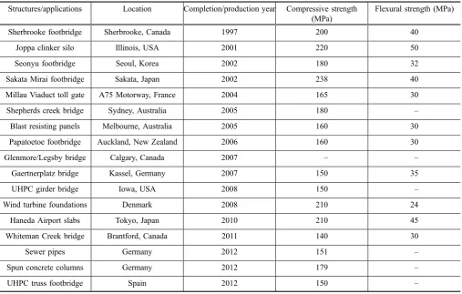
unique structures in the near future. UHPC potential appli-cations include tall structures, rehabilitation works, structural and non-structural elements, machine parts and military structures. Lighter weight structures owing to smaller cross-sections can be made using UHPC. Therefore, UHPC can be effectively utilized in the precast concrete industry. More-over, UHPC was widely used in pedestrian footbridges and highway bridges. For example, the first UHPC footbridge in Canada was constructed in 1997. In the United States, Wapello County Mars Hill was the first highway trans-portation bridge constructed with UHPC in 2006. In the Kinzua Dam Stilling Basin, UHPC was used for rehabilita-tion and strengthening purposes. Furthermore, architec-turally and aesthetically appealing structures can be made using UHPC (Schmidt et al. 2004, 2012; Fehling et al. 2008). Table1 summarizes some of the existing UHPC applications around the world. In the present study, an extensive review of literature on UHPC properties was conducted and summarized in tabular representation for a user friendly access to this scattered information.
2. UHPC Composition
The key factor in producing UHPC is to improve the micro and macro properties of its mixture ingredients to ensure mechanical homogeneity, maximum particle packing density and minimum size of flaws (Schmidt et al. 2005; Vernet 1)Department of Civil Engineering, University of
Engineering and Technology, Lahore, Pakistan. 2)Department of Civil and Environmental Engineering, Western University, London, ON, Canada.
*Corresponding Author; E-mail: [email protected] CopyrightÓThe Author(s) 2016. This article is published with open access at Springerlink.com
International Journal of Concrete Structures and Materials Vol.10, No.3, pp.271–295, September 2016
2004; Shah and Weiss 1998; Wille et al. 2011; Shi et al. 2015). Table2shows the range of UHPC constituents used in various studies for the successful production of UHPC.
2.1 Binders
A relatively high proportion of cement is used in UHPC compared to that used in normal-strength (NS) and high-per-formance concrete (HPC) (Schmidt and Fehling2005; Ghafari et al.2015). It was observed that increasing the cement content increased the UHPC compressive strength; however, beyond an optimum cement content (around 1700 kg/m3(106 lb/ft3), compressive strength tends to decline likely due to limited participation of aggregates (Talebinejad et al.2004). Cement with moderate Blaine fineness (4000 cm2/g (281,240 in2/lb)) and tri-calcium aluminate (C3A) content lower than 6 % is
preferred due to its lower water demand (Wille et al.2011). Special micro-fine cements with particle size smaller than regular Portland cement were also used for developing UHPC (Strunge and Deuse2008).
Because of the very low water/binder ratio (w/b) of UHPC, only part of the total cement hydrates and the un-hydrated cement can be replaced with crushed quartz, fly ash or blast furnace slag. For instance, up to 30, 36 and 40 % by volume of cement in UHPC mixtures can be replaced with crushed quartz, blast furnace slag or fly ash, respectively, without compromising the compressive strength (Ma and Schneider2002; Soutsos et al.2005; Yazici2006).
Moreover, the addition of silica fume as a binder can improve the workability of UHPC by filling voids between coarser particles owing to its much finer particle size and optimal spherical shape. In addition to this microfiller effect, silica fume also enhance the strength properties of UHPC through its pozzolanic reactions (Ma and Schneider 2002; Richard and Cheyrezy1995). Various studies (Ma and Sch-neider 2002; Matte and Moranville 1999; Chan and Chu 2004; Xing et al.2006) recommended silica fume dosages of 20–30 % of the total binder material to achieve denser particle packing and pozzolanic reactivity in UHPC, leading to higher strength properties. For instance, 25 % by cement weight of low carbon content (\0.5 %) silica fume was recommended as an optimum dosage in UHPC (Wille et al.2011).
2.2 Water/Binder Ratio
A very low water/binder ratio (w/b) is used in UHPC mixtures. Minimum w/b of 0.08 was reported by Richard and Cheyrezy (1995); however, this ratio did not ensure dense particle packing. An optimum w/b ratio of 0.13–0.20 was suggested in previous studies (Richard and Cheyrezy 1995; Larrard and Sedran 1994; Gao et al. 2006; Wen-yu et al. 2004; Shi et al. 2015) to achieve maximum relative density and spread flow. However, researchers (Wille et al. 2011; Droll2004) also achieved compressive strength higher than 150 MPa (22 ksi) using 0.25 w/b. Therefore, it can be argued that the w/b is not the sole strength governing parameter of UHPC. The curing regime, properties of mix-ture ingredients, mixing procedures and mixer type are also important parameters.
2.3 Superplasticizer
The reduced workability of UHPC due to its very low w/b can be resolved by adding effective superplasticizers (SP). The required SP dosage significantly depends on the com-patibility between the mixture ingredients and the type of SP used. Improved compatibility can lead to lower SP dosage. For example, an UHPC mixture incorporating a limestone micro-filler is more workable and compatible compared to a mixture incorporating higher surface area metakaolin at the same SP dosage (Rougeau and Burys 2004). Furthermore, stepwise or delayed addition of SP (rather than adding the SP at once) was found to enhance the workability of UHPC mixtures owing to an improved dispersing effect (Tue et al. 2008). Various studies (Schmidt et al.2004,2012; Fehling et al.2008) used SP dosages ranging between 1 and 8 % by cement weight for enhancing the workability of UHPC mixtures. Generally, SP dosages of 1.4–2.4 % by cement weight are recommended (Wille et al.2011).
2.4 Aggregates
Generally, failure in conventional concrete is initiated by damage at the interfacial transition zone (ITZ) between the cementitious matrix and aggregates (Jun et al. 2008). Therefore, eliminating coarse aggregates in UHPC mixtures reduces such weaknesses induced by such ITZ. In addition, mitigating the ITZ flaws results in overall lower porosity in the matrix, leading to enhanced mechanical strength (Mehta et al. 2006). The fine aggregate like quartz sand plays an important role in reducing the maximum paste thickness (MPT), which is also a key factor in the mixture design of UHPC. An optimum sand-to-cement ratio was found to be 1.4 for a quartz particle size of 0.8 mm (0.031 in) (Wille et al.2011).
2.5 Steel Fibers
Due to its very high strength and homogeneity, UHPC is very brittle; yet it can be made ductile by adding steel fibers (Bayard and Ple2003; Graybeal 2006; Wang et al. 2015). The most commonly used size of steel fibers is 13 mm (0.5 in) in length and 0.20 mm (0.008 in) in diameter (Schmidt et al.2004,2012; Fehling et al. 2008). Richard and Cheyr-ezy (1995) recommended using 2 % by mixture volume of steel fibers for an economical and workable UHPC mixture design.
2.6 Nano-materials
The success of mixture design of UHPC is highly dependent on achieving highest particle packing density and ultra-high consolidation of the concrete matrix. Therefore, the addition of nano particles produced from silicon dioxide (SiO2), aluminum oxide (Al2O3), iron oxide (Fe2O3),
tita-nium dioxide (TiO2) or zirconium dioxide (ZrO2) can fill the
H) through possible pozzolanic reactions, and reduce cal-cium leaching and weak zones of calcal-cium hydroxide (Droll 2004; Sobolev and Amirjanov2004; Bjornstrom et al.2004; Korpa and Trettin 2007). This can cause significant improvements in mechanical and durability properties of UHPC (Ghafari et al. 2012). Researchers (Ghafari et al. 2012; Shakhmenko et al.2012) recommended using 1–5 % by cement weight of nano-particles in UHPC mixture design for successful improvement of UHPC material properties.
Ghafari et al. (2014) reported an increase in compressive strength of UHPC with higher dosage of nano-silica (nS). An optimum amount of nS was reported to be 3.74 % by binder mass (Rong et al.2015; Yu et al. 2014). Moreover, it was observed that the addition of nS in UHPC mixtures decreased the corrosion rate of steel rebar (Ghafari et al. 2015). It was also reported that UHPC mixtures incorpo-rating nS showed reduction in capillary porosity compared to that of UHPC mixtures without nS (Ghafari et al. 2012, 2014). Fadzil et al. (2013, 2014) used 1 % of nano metakaolin and observed enhanced microstructure of UHPC leading to reduced chloride ions penetration in UHPC. Incorporating nano CaCO3in UHPC improved the hydration
process at early-age, producing denser particle packing, and improving mechanical properties (Li et al.2015). Huang and Cao (Huang and Cao2012) used nano-CaCO3and observed
a 17 % increase in compressive strength compared to that of the control UHPC specimens. Falikman et al. (Falikman et al.2012) reported smog eating and self-healing properties
of UHPC incorporating nano TiO2particles through a
photo-catalysis effect. It was observed that mixtures incorporating nano Fe2O3increased the mechanical strength of UHPC and
induced self-sensing abilities (Li et al.2004). Furthermore, carbon nanotubes and nanofibers can be used in UHPC for further improving its mechanical properties. Therefore, it can be concluded that the use of nano materials in UHPC can lead to a denser microstructure and better mechanical and durability performance.
3. Mixture Design of UHPC
The mixture design of UHPC should be economical and sustainable for achieving denser matrix, reduced porosity and improved internal microstructure, leading to superior mechanical and durability properties. Various models have been reported for the mixture design of UHPC. For instance, Larrad and Sedran (1994) proposed a linear packing density model (LPDM) for the mixture design of UHPC. However, the LPDM model did not focus on the relationship between materials proportions and packing density due to the linear nature of LPDM model. Therefore, this model was improved considering the virtual density theory and a new model known as solid suspension model (SSM) was developed (Larrard and Sedran1994). Afterwards, based on the com-paction index concept and virtual packing density, the compressible packing model (CPM) for the mixture design
Table 1 Example applications of UHPC around the world.
Structures/applications Location Completion/production year Compressive strength (MPa)
Flexural strength (MPa)
Sherbrooke footbridge Sherbrooke, Canada 1997 200 40 Joppa clinker silo Illinois, USA 2001 220 50 Seonyu footbridge Seoul, Korea 2002 180 32 Sakata Mirai footbridge Sakata, Japan 2002 238 40 Millau Viaduct toll gate A75 Motorway, France 2004 165 30 Shepherds creek bridge Sydney, Australia 2005 180 – Blast resisting panels Melbourne, Australia 2005 160 30 Papatoetoe footbridge Auckland, New Zealand 2006 160 30 Glenmore/Legsby bridge Calgary, Canada 2007 – – Gaertnerplatz bridge Kassel, Germany 2007 150 35 UHPC girder bridge Iowa, USA 2008 150 – Wind turbine foundations Denmark 2008 210 24 Haneda Airport slabs Tokyo, Japan 2010 210 45 Whiteman Creek bridge Brantford, Canada 2011 140 30
Sewer pipes Germany 2012 151 –
Spun concrete columns Germany 2012 179 –
UHPC truss footbridge Spain 2012 150 –
of UHPC was proposed (Larrard and Sedran2002). Yu et al. (2014) optimized the mixture ingredients of UHPC using a modified Andreasen and Andersen model with various dis-tribution modules.
Geisenhansluke and Schmidt (2004) designed a locally produced UHPC mixture based on particle shape, size and density. Moreover, it was reported that the cement content can be lessened by utilizing multi-grained fine particles. An ecological UHPC mixture was developed by Fennis et al. (2009) based on particle packing technology, which reduced the cement content by 50 %. A robust mixture design of UHPC was proposed by Lohas and Ramge (Lohaus and Ramge2008) based on superplasticizer for achieving desired workability of the paste depending on the water-to-powder ratio. Wille et al. (Wille et al.2011) developed UHPC using local materials without any special type of mixer and heat treatment based on spread flow properties. Using a modified Andreasen and Andersen particle packing model, a densely compacted UHPC was developed with a cement content lower than 675 kg/m3(Yu et al.2014).
Furthermore, statistical models were also proposed for the mixture design of UHPC. For example, adaptive neuro fuzzy interface system (ANFIS) was used for proportioning the mixture ingredients of UHPC (Taghaddos et al. 2004). A response surface methodology (RSM) was adopted by Ghafari et al. (2014) for predicting the maximum flexural strength of self-compacting steel fiber-reinforced UHPC with varying steel fiber contents. In another study, Ghafari et al. (2015) used a statistical mixture design (SMD) model for optimizing the mixture design of UHPC. The effect of
individual ingredients and their interactions were studied for predicting the compressive strength of UHPC using mini-mum cement content (Ghafari et al.2015). Moreover, arti-ficial neural network (ANN) models were developed for predicting the performance of UHPC under different curing conditions (Ghafari et al.2012,2015). It was found that the polynomial regression model was suitable for predicting the desired properties of UHPC mixtures (Ghafari et al. 2014, 2015). The optimum amount of cement and silica fume was 24 and 9 % by volume of concrete respectively, based on ANN models analysis (Ghafari et al.2015). Gha-fari et al. (2012,2015) concluded that the ANN model was more efficient compared to the SMD approach for the characterization of UHPC material properties. Van and Ludwig (2012) designed UHPC mixtures using the D-opti-mal design technique and reported a good correlation with experimental results.
4. Fresh Properties of UHPC
4.1 Air Content
The reported air content in UHPC mixtures ranged from 0.3 to 5.4 % by mixture volume depending on the mixture design (Wille et al.2011). Higher w/b and SP dosage tend to increase the air content in UHPC mixtures (Table3). Fur-thermore, the total air content is highly dependent on the type of mixer used (Ingo et al.2004). For instance, labora-tory mixers with higher mixing speed lead to sticky con-sistency of the paste, consequently increasing the air content
Table 2 Typical composition of UHPC.
UHPC constituents Range (% by weight)
Cement 27–40
Silica fume 6–12
Quartz powder 7–14
Sand 35–45
Superplasticizer 0.5–3
Water 4–10
Steel fiber 0–8
Data collected from Schmidt et al. (2004,2012), Fehling et al. (2008) and Talebinejad et al. (2004).
Table 3 Effect of w/b and superplasticizer on air content of UHPC.
References w/b Superplasticizer Air content (%)
Ingo et al. (2004) 0.25 – 4.3
(typically 4.3 %). On the other hand, ring type mixers for instance in precast plants apply high shear forces, leading to relatively lower air content (approximately 3.2 %) for the same mixture composition and proportions (Ingo et al. 2004). It was reported that an air content in UHPC of below 1 % can be achieved using a vacuum accessory with pres-sure of 50 mbar (Ingo et al. 2004). Also, the concrete placement method significantly affects the air content. For instance, concrete placement into formwork using spiral pump reduced the air content from 2.9 to 1.3 % (Ingo et al. 2004). Furthermore, the delayed addition of SP decreased the viscosity of the UHPC mixture and consequently reduced the air content from 2.5 to 1 % (Tue et al.2008). A threshold value of 2 % air content by mixture volume was considered adequate for improved spread flow and enhanced properties of UHPC mixtures (Wille et al.2011).
4.2 Setting Time
According to Habel et al. (2006), the setting time of UHPC is defined as ‘‘the time when the mixture attains a stiffness of 1000 MPa (145 ksi) and autogenous shrinkage initiates’’. In another study, Graybeal (2006) defined the initial setting time as ‘‘a penetration resistance of 3.45 MPa (0.5 ksi) at 15 h after casting’’ and the final setting time as ‘‘a penetration resistance of 27.60 MPa (4 ksi) at about 18–20 h after casting’’ based on AASHTO T197 (2000). Generally, the reported setting time of UHPC ranged from 6 to 12 h depending on the mixture design (Richard and Cheyrezy 1995; Yoo et al.2013; Kazemi and Lubell2012). However, some studies (Brown 2006; Graybeal 2007; Habel 2004; Morin et al. 2001) showed that the setting time for UHPC can be delayed for up to 30–40 h due to the set retarding effect of high SP dosage. Furthermore, it was observed that surface covering of freshly mixed UHPC delayed its setting time (Yoo et al.2013).
4.3 Workability
The handling of UHPC during casting is a major problem due to its low w/b and reduced workability. The workability
of UHPC is also affected by the addition of steel fibers. Studies showed that UHPC mixtures incorporating fibers with smaller aspect ratio are more workable even at higher fiber dosage compared to that of mixtures with fibers having larger aspect ratio. For instance, 6 mm (0.25 in) long and 0.15 mm (0.006 in) diameter steel fibers can be used up to 10 % by mixture volume, while 12 mm (0.5 in) long and 0.15 mm (0.006 in) diameter fibers can be used up to 3 % by mixture volume without affecting the mixture workability (Wille et al. 2011; Rossi2005). Wille et al. (2011) recom-mended adopting 200–350 mm (8–14 in) limit for the flow diameter spread according to ASTM C230 (1998) for dense UHPC without fibers. Furthermore, the spread flow can be increased by utilizing ultra-fine or nano-particle materials. For example, a 16 % increase in spread flow was observed with the addition of 1 % by cement weight of nano-silica (Shakhmenko et al.2012).
5. Mechanical Properties
5.1 Compressive Strength
5.1.1 Effect of Specimen Size and Shape
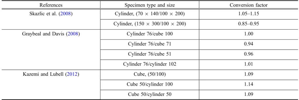
It was found that the specimen size has a significant influ-ence on the measured compressive strength of UHPC. For instance, Skazlic et al. (2008) observed 21 % increase in cylinder compressive strength for a specimen size of 709140 mm (2.7595.50 in) compared to that of 1009200 mm (3.9497.87 in). This is likely due to the higher probability of encountering larger size flaws in larger specimens (Graybeal2006; Ahlborn et al.2008). Moreover, it was observed that cube specimens exhibited higher strength compared to that of cylindrical specimens due to the well-known confinement effect of the testing machine platens (Kazemi and Lubell2012; Graybeal and Davis2008). Table 4 shows proposed conversion factors for various UHPC speci-men types and sizes. Using 70 mm (2.75 in) cube specispeci-mens was recommended considering the machine capacity and cylinder end grinding concerns (Graybeal and Davis2008).
Table 4 Conversion factors for various type and size of UHPC specimens for compressive strength.
References Specimen type and size Conversion factor Skazlic et al. (2008) Cylinder, (709140/1009200) 1.05–1.15
Cylinder, (1509300/1009200) 0.85–0.95 Graybeal and Davis (2008) Cylinder 76/cube 100 1.00
5.1.2 Effect of Pre-treatment
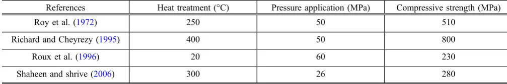
The rate of hydration in UHPC mixtures can be increased through proper heat treatment. The application of thermal treatment advances pozzolanic reactions, leading to forma-tion of addiforma-tional calcium silicate hydrates (C–S–H) (Heinz and Ludwig2004; Muller et al.2008). These C–S–H phases fill small pores, leading to denser microstructure and con-sequently higher mechanical properties (Graybeal 2006; Muller et al. 2008; Collepardi et al. 1997; Cwirzen 2007; Lee and Chisholm 2005). The rate of cement hydration reactions increases at higher heat treatment temperature. For example, hydration products formation increased from 10 to 55 % at 8 h when the temperature was raised from 90 to 250°C (194–482°F) (Zanni et al.1996). Generally, the heat treatment typically applied for UHPC specimens is from 90 to 400°C (194–752°F) for 2–6 days (Graybeal2006; Heinz and Ludwig2004; Richard and Cheyrezy 1994; Teichmann and Schmidt2004). A 40 % average increase in compressive strength was observed for 90°C (194°F) heat treatment compared to that of untreated control specimens (Soutsos et al.2005; Xing et al.2006; Bonneau et al.1997). The time of starting the thermal treatment had an insignificant effect on the UHPC compressive strength (Ahlborn et al. 2008). For instance, only 4 % difference in compressive strength was observed for UHPC specimens thermally cured for 2 days right after demolding, compared to when the thermal treatment was applied after 10 days from demolding (Ahl-born et al. 2008). This should allow the pre-caster in fabri-cating various elements at different timelines and curing them together, leading to energy savings. Furthermore, during the setting of UHPC, the application of a confining pressure contributes towards increased compactness and denser microstructure, thus leading to higher strength and durability properties (Table5). This can be attributed to the removal of entrapped air voids and free water (Richard and Cheyrezy1995; Cwirzen et al.2008).
5.1.3 Effect of Steel Fibers
It was observed that the addition of steel fibers changes the failure mode of UHPC specimens from complete damage or sudden explosion to a somewhat ductile behavior where specimens can remain intact without chipping and spalling (El-Dieb 2009). Various researchers (Reda et al. 1999; Schmidt et al. 2003) reported that the UHPC compressive strength was not influenced by the addition of high dosages of steel fibers. Increased concentration of steel fibers can create fiber bundling, thus leading to weak spots, which can reduce the efficiency of fibers, hence decreasing compressive
strength. A slight increase in compressive strength due to fiber addition can be observed if proper thermal treatment is applied (Soutsos et al.2005; Jun et al.2008; Bonneau et al. 1997; Herold and Muller2004). This mainly depends on the type of fibers and their dosage (Soutsos et al.2005; Bonneau et al. 1997; Herold and Muller 2004). For example, approximately 30 % increase in compressive strength was observed with the addition of 2.5 % by mixture volume of steel fibers when specimens were subjected to thermal treatment (Soutsos et al. 2005; Graybeal 2006; Lee and Chisholm 2005; Bonneau et al. 1997). This increase in UHPC compressive strength was attributed to the enhanced tolerance of lateral strains owing to steel fiber addition (Kazemi and Lubell2012; Hassan et al. 2012; Orgass and Klug 2004; Magureanu et al. 2012; Ye et al. 2012). Fur-thermore, it was reported that the addition of fibers resulted in less entrapped air, leading to improved density and hence higher compressive strength (Abbas et al.2015).
5.1.4 Effect of Casting Direction
No significant effect of the casting direction was observed on the compressive strength of UHPC. For instance, Stiel et al. (2004) reported a compressive strength difference of less than 2 % for UHPC cube specimens when loaded per-pendicular and parallel to the casting direction.
5.1.5 Effect of Loading Rate
Due to its high compressive strength, more time is required to break UHPC specimens at low loading rate. For instance, a 1509300 mm (6912 in) UHPC cylinder broke after 13 min when a 0.24 MPa/s (35 psi/s) loading rate was applied. Therefore, higher loading rate up to 1.0 MPa/s (150 psi/s) can be applied without significantly affecting the strength properties of UHPC in order to reduce the failure time (Kazemi and Lubell 2012; Graybeal et al. 2003). According to AFGC-SETRA (2002) guidelines, a loading rate ranging between 0.24 and 1.7 MPa/s (35–250 psi/s) affected the UHPC compressive strength by less than 4 %.
5.2 Elastic Modulus
The compressive stress–strain curve of UHPC typically shows a linear elastic portion up to 80–90 % of the maxi-mum stress value (Graybeal 2007; Cheyrezy1999). It was observed that the addition of fibers in UHPC did not sig-nificantly influence its elastic modulus. For example, only 7 % increase in the elastic modulus was observed with the addition of 2 % by mixture volume of steel fibers compared
Table 5 Effect of pressure application on UHPC compressive strength.
References Heat treatment (°C) Pressure application (MPa) Compressive strength (MPa)
Roy et al. (1972) 250 50 510
Richard and Cheyrezy (1995) 400 50 800
Roux et al. (1996) 20 60 230
to that of control UHPC without fibers (Bonneau et al. 1996). Furthermore, the elastic modulus of UHPC is a function of heat treatment (Graybeal2006; Graybeal2007; Richard and Cheyrezy 1994). For instance, the modulus increased from 57 to 70 GPa when specimens were sub-jected to a high temperature of 250°C (482 °F) for 2 days (Richard and Cheyrezy1994). Various models that relate the elastic modulus and compressive strength of UHPC are shown in Table6.
5.3 Flexural Strength
UHPC exhibits high flexural strength properties due to its dense particle packing and steel fiber addition (Graybeal et al. 2003; Kim et al.2008). Researchers (Cheyrezy et al. 1998; Perry and Zakariasen2004) reported flexural strength values of up to 48 MPa (7.0 ksi) for UHPC depending on its mixture design and curing regime.
5.3.1 Effect of Sample Preparation Technique and Concrete Pouring Direction
No significant effect of the casting direction on the initial stiffness of UHPC beams subjected to bending was observed (Steil et al.2004). However, it was reported that vertically
cast beam specimens showed almost five times lower flex-ural strength compared to horizontally cast beam specimens (Steil et al.2004). This was attributed to the difference in fiber orientation. Fibers were oriented perpendicular and parallel to the crack surface for horizontally and vertically cast beams, respectively. It was also observed that the failure surface was smoother for vertically cast beams, whereas horizontally cast beams showed rougher and wrinkled failure surfaces (Steil et al.2004).
Moreover, the flexural strength of UHPC was also dependent on the pouring method of concrete into molds (Table7). For instance, the pouring of concrete from one end of the mold only showed an increased flexural strength by 56 % compared to that of the same concrete poured at dif-ferent locations into the mold (Lappa et al.2004). This was attributed to the strong fiber orientation (higher number of fibers crossing at particular sections) parallel to the flow direction (Lappa et al. 2004; Pansuk et al.2008). Further-more, Wille and Parra-Montesinos (2012) observed that beam specimens cast only at their middle point exhibited lower peak strength compared to that of similar specimens cast in layers with higher chute speed (0.50 m/s (20 in/s)). A funnel like pattern was observed for beams cast only at the
Table 6 Relationship between elastic modulus and compressive strength of UHPC.
References Models
ACI 363R-92 (HPC) (1997) E¼3300pffiffiffiffifc0þ6:9 Ma and Schneider (2002) E¼16;364ln fc0 34;828
Sritharan et al. (2003) E¼4150 ffiffiffiffif0 c p
Ma et al. (2004) E¼19;000 ffiffiffiffiffiffiffiffiffiffiffif0
c=10
3 p
Graybeal (2007) E¼3840 ffiffiffiffif0 c p
Table 7 Effect of casting method on flexural capacity of UHPC.
References Steel fiber Curing conditions Casting direction/ pouring method
Flexural strength (MPa) L/D (mm/mm) (%)
Steil et al. (2004) 6/–?13/– 5?1 90°C in water tank for 7 days
Horizontal 49.6 Vertical 11.7 Lappa et al. (2004) 20/0.3 2.5 Fog room at 99 % RH
until 28 days
Concrete pouring at one end only
29.8
Concrete pouring at different locations
19.1
Kim et al. (2008) 15/– 2 – Longitudinal (parallel to flexural tension)
72.0
Vertical (perpendicular to flexural tension)
42.0
Yang et al. (2010) 13/0.2 2 90°C for 3 days and 20°C wet curing
thereafter
End casting of beams 62.6 Middle casting of
beams
54.0
Wille and Parra-Montesinos (2012)
13/0.2 1.50 Stored in water at 20°C
Middle casting 15.8 Layer casting 21.8
middle point, leading to arranging the fibers along the fun-nel. However, the beams cast in layers with higher chute speed (0.50 m/s (20 in/s)) formed strong thin layers and desired fiber alignment along the beam axis, thus achieving increased flexural strength (Wille and Parra-Montesinos 2012). On the other hand, beams cast with lower chute speed (0.13 m/s (5 in/s)) exhibited lower flexural strength com-pared to that of specimens cast at their middle only. This was attributed to the fact that the slow movement of chute formed thick layers of snake like pattern, leading to vertical orien-tations of fibers, consequently reducing the flexural strength (Wille and Parra-Montesinos2012). It was observed that the concrete pouring location is also an important factor in achieving higher flexural strength (Table7). For example, beams cast from the mold end exhibited 16 % higher flex-ural strength compared to that of beams cast at the middle of the mold (Yang et al.2010). This was ascribed to better flow properties of beams cast from the mold end, leading to improved fiber orientation and hence increased flexural strength (Yang et al.2010).
5.3.2 Effect of Fibers
It was observed that fibers significantly affect the UHPC flexural properties (Kazemi and Lubell 2012; Magureanu et al. 2012). The flexural strength of UHPC increased lin-early with increased fiber dosage (Kang et al. 2010) (Table8). An increase in flexural strength by 144 % was observed with 2.5 % by mixture volume of steel fibers addition compared to that of control beams without fibers (Magureanu et al.2012). The main role of fibers is to prevent the intergrowth of micro-cracks by absorbing tensile stres-ses, and consequently macro-cracks are prevented (Orgass and Klug 2004). Moreover, beam specimens incorporating fibers showed multiple cracks and exhibited steadier drop in load carrying capacity rather than a sudden drop in load after formation of the first crack (Kazemi and Lubell2012). The failure was characterized by a single vertical macro-crack with multiple micro-cracks for UHPC incorporating steel fibers (Orgass and Klug2004).
Furthermore, it was observed that the flexural capacity of UHPC was also dependent on the aspect ratio of fibers. For instance, UHPC mixtures incorporating higher aspect ratio fibers had increased flexural capacity compared to that of those with lower aspect ratio fibers. This was attributed to the fact that mixtures incorporating small diameter fibers (higher aspect ratio) have increased number of fibers per unit volume of concrete, leading to more fibers bridging cracks, and hence increased flexural capacity (Ye et al. 2012). Fur-thermore, a hybrid mixture of steel and polyvinyl alcohol (PVA) fibers significantly improved the flexural behavior of UHPC compared to their individual addition (Bornemann and Faber 2004). It was also observed that alkali resistant (AR) glass fibers improved the peak load carrying capacity by increasing the energy required for the development of micro-cracks. However, a reduction in ductility using AR-glass fibers was observed compared to that for steel fibers (Lohaus and Anders2004).
5.3.3 Effect of Specimen Size
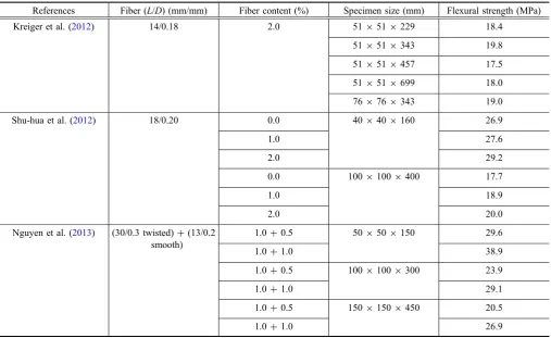
The flexural strength of UHPC decreased as the specimen size increased (Table8). For instance, a specimen size of 70091509150 mm (27.5095.9095.90 in) showed a 33 % decrease in flexural strength compared to that of a similar specimen with a size of 160940940 mm (6.3091.5791.57 in) (Bornemann and Faber2004). This was ascribed to the higher wall effect of fibers in smaller specimens (Kazemi and Lubell2012; Magureanu et al.2012; Wille and Parra-Montesinos 2012; Kooiman 2000). It was observed that the fiber orientation near the mold surfaces had two dimensional (2-D) patterns which changed to three dimensional (3-D) patterns away from the mold surfaces (Reineck and Greiner2004). The 3-D fiber orientation is not favorable for higher flexural strength due to smaller equiv-alent fiber contents in the direction of flexural stresses. The smaller specimens have more tendency to form favorable 2-D patterns along the cross-section, leading to higher flexural strength (Kazemi and Lubell 2012; Reineck and Greiner 2004). It was also observed that the smaller beam specimens showed higher ductility compared to that of the larger specimens. This was attributed to the improved fiber orientation in the smaller specimens (Orgass and Klug 2004). Furthermore, it was reported that the average number of cracks and their spacing decreased as the specimen size decreased (Nguyen et al.2013). This was directly related to their increased flexural tensile strain capacity (Nguyen et al. 2013). AFGC-SETRA (2002) recommended a reduction factor of 9 % when the specimen height increases from 100 mm (3.97 in) to 150 mm (5.90 in).
5.3.4 Effect of End Supports
It was observed that UHPC beam specimens tested under high frictional support exhibited 30–60 % higher flexural capacity, depending on the fiber dosage, compared to that of similar beam specimens tested under low frictional support (Wille and Parra-Montesinos2012). This was attributed to the increased internal moment due to the additional contri-bution of the horizontal reaction provided by the frictional force depending on the friction coefficient (Wille and Parra-Montesinos2012).
Table 8 Effect of steel fiber dosage and beam size on flexural capacity of UHPC.
References Fiber (L/D) (mm/mm) Fiber content (%) Specimen size (mm) Flexural strength (MPa) Collepardi et al. (1997) 13/0.18 2.5 15091509600 20.2
409409160 48.3 Herold and Muller (2004) 8/0.17 0.0 409409160 21.1
0.5 25.3
2.5 34.1
4.0 46.2
Bornemann and Faber (2004)
9/0.15 2.0 15091509700 22.0
Guvensoy et al. (2004) 6/0.15 5.0 709709280 30.3
5.5 49.2
6.0 54.4
Orgass and Klug (2004) 13/0.16 0.0 15091509700 10.6
1.0 11.9
2.0 13.4
0.0 10091009500 9.8
1.0 11.2
2.0 14.7
0.0 409409160 9.9
1.0 11.6
2.0 18.3
Soutsos et al. (2005) 12/0.16 0.0 409409160 18.4
1.5 37.3
2.0 40.3
Allena and Newtson (2010) 13/– 0.0 7591009400 10.9
1.5 18.3
Wille and Parra-Montesinos (2012)
13/0.20 1.5 15291529508 14.8 10291029406 15.8 Magureanu et al. (2012) 25/0.40?6/0.17 0.0 409409160 13.9
2.5 34.0
0.0 10091009300 9.4
2.5 23.0
Kazemi and Lubell (2012) 13/0.2 0.0 509509150 22.1
2.0 29.1
4.0 48.0
0.0 10091009300 15.0
2.0 23.1
maximum bond stress depending on the UHPC mixture design and proportions (Holschemacher et al. 2004). The shape of the bond stress-slip curve is highly dependent on the loading rate. For instance, the smaller the loading rate (0.001 mm/s), the steeper was the ascending slope (higher bond stiffness) and curve flattening becomes steadier in the descending branch of the bond stress-slip curve. However, higher loading rate (i.e. 0.1 mm/s) yielded higher bond stress and corresponding displacement (Holschemacher et al. 2004). Moreover, it was observed that the bond strength of rebar embedded in steel fiber-reinforced UHPC had less brittle pull-out failure and exhibited larger deformations compared to that of similar rebar embedded in UHPC without steel fibers (Maroliya2012).
5.5 Reinforcement Cover
UHPC elements typically require smaller reinforcement cover due to the improved mechanical and durability properties. UHPC incorporating steel fibers exhibits higher tensile properties, thus preventing splitting cracks and concrete spalling (Holschemacher et al. 2004). Further-more, the decreased permeability due to the very low porosity of UHPC mitigates the intrusion of aggressive species (e.g. chloride ions) into the hardened matrix and the subsequent attack on the steel reinforcement even when the reinforcement cover is relatively thin. Smaller reinforcement covers in UHPC members further reduce the cross-sectional dimensions leading towards economical construction.
5.6 UHPC Under Dynamic and Impact Loading Very limited literature is available on the behavior of UHPC under dynamic effects such as earthquake or impact loading. Rebentrost and Wight (2008) reported that the application of UHPC reduced the earthquake design loads due to decreased overall structural weight, leading to more cost-effective construction. UHPC has also shown excellent performance against impact loading. Farnam et al. (2008) tested UHPC panels against an impact load of 8.5 kg and concluded that the member thickness, fiber type, fiber length and fiber dosage were important parameters responsible for impact resistance (Farnam et al.2008). UHPC has the ability to dissipate higher energy under impact loads than that of NSC due to its high strength and ductility properties (Bindiganavile et al.2002). Sun and Jiao (2011) reported 1.5 times increase in impact axial tensile strength of steel fiber-reinforced UHPC specimens compared to that of NSC. Soe et al. (2013) studied the impact resistance of engineered cementitious composite (ECC) panels and observed higher impact resistance of hybrid fiber ECC compared to that of plain concrete.
Astarlioglu and Krauthammer (2014) studied the behavior of UHPC columns under blast loading using a single degree of freedom approach. UHPC columns exhibited around 30 % smaller displacement compared to that of control NSC columns. Moreover, UHPC can resist four times higher impulsive loadings before failure compared to that of NSC (Astarlioglu and Krauthammer 2014). It was observed that shear is the governing behavior for UHPC under blast
Table 8 continued
References Fiber (L/D) (mm/mm) Fiber content (%) Specimen size (mm) Flexural strength (MPa) Kreiger et al. (2012) 14/0.18 2.0 519519229 18.4
519519343 19.8 519519457 17.5 519519699 18.0 769769343 19.0 Shu-hua et al. (2012) 18/0.20 0.0 409409160 26.9
1.0 27.6
2.0 29.2
0.0 10091009400 17.7
1.0 18.9
2.0 20.0
Nguyen et al. (2013) (30/0.3 twisted)?(13/0.2 smooth)
1.0?0.5 509509150 29.6
1.0?1.0 38.9
1.0?0.5 10091009300 23.9
1.0?1.0 29.1
1.0?0.5 15091509450 20.5
loading (Millard et al. 2010). Barnett et al. (2010) tested UHPC panels of 3.5091.30 90.10 m in size under blast loading using 100 kg TNT placed at different distances (7, 9 and 12 m). UHPC panels with conventional rebar rein-forcement were able to sustain blast pressure of around 2500 kPa; UHPC panels incorporating steel fibers broke into two pieces at a blasting pressure of 500 kPa (Schleyer et al. 2011). These experimental results correlated well with numerical findings (Mao et al. 2014). Mao et al. (2015)
studied the effect of blast loading on UHPC slabs incorpo-rating different types and dosages of steel fibers. It was observed that an increase in fiber dosage improved the blast resistance of UHPC slabs. It was also observed that UHPC mixtures incorporating long steel fibers exhibited enhanced performance under impact loading compared to that incor-porating short fibers (Yu et al. 2014). Aoude et al. (2015) tested UHPC columns under simulated blast loading using a shock tube testing facility. It was observed that the concrete
Table 9 Bond strength of steel fiber and rebar in UHPC.
References Reinforcement type Diameter (mm) Embedded length (mm)
Curing regime Bond strength (MPa)
Behloul (1996) 13 mm steel fiber 0.15 – – 11.5 Chan and Chu (2004) 0.16 10 85°C and 90 % RH
for 3 days
5.5
Lee et al. (2010) 13 mm steel fiber at 0o 0.20 6.5 Steam curing 90°C for
2 days
6.8 13 mm steel fiber at
15o
0.20 10.8
13 mm steel fiber at 30o
0.20 12.7
Wille and Naaman (2012)
13 mm steel fiber 0.20 6.5 20°C (Laboratory environment)
10.4 30 mm steel fiber
twisted
0.30 46.9
30 mm steel fiber hooked
0.30 42.2
Park et al. (2014) 30 mm smooth steel fiber
0.30 15 Water curing at 90°C for 3 days
9.9
30 mm hooked steel fiber
0.37 11.7
62 mm hooked steel fiber
0.77 11.4
30 mm twisted steel fiber
0.30 6 32.0
Collepardi et al. (1997) Deformed rebar 20 – Standard 28.4 Cheyrezy et al. (1998) Prestressing strand 13 – Standard 35.0 Cheyrezy et al. (1998) Prestressing wire 5 – Standard 10.0
Reineck and Greiner (2004)
Deformed rebar 4 8 – 46.0
Holschemacher et al. (2004)
Deformed rebar 10 15 Under water, 3 days 34.0 Deformed rebar 10 Under water, 7 days 47.0 Deformed rebar 10 Under water, 28 days 68.0 Deformed rebar 10 Under water, 56 days 70.0 Holshemacher et al.
(2005)
Deformed rebar 10 – – 56.0
Lee et al. (2005) Epoxy coated rebar 10 – – 12.7 Tuchlinski et al. (2006) Prestressing strand 13 – – 15.0 Maroliya (2012) Deformed rebar 8 75 Hot water curing 4.8
type, fiber type and dosage, longitudinal reinforcement ratio and spacing between transverse reinforcement were the important parameters that effect the failure pattern of UHPC columns subjected to blast loading (Aoude et al.2015).
UHPC application is desirable in military structures where impact resistance due to blast loading is of concern. UHPC structural elements showed improved behavior against explosive load compared to that of HPC and NSC (Millon et al.2012; Ngo et al. 2007). The development of multiple micro-cracks (crack width of about 0.50 mm (0.02 in)) without fragmentation or spalling was observed in UHPC members, leading to decreased global structural damage. The improved cracking behavior was attributed to the addition of high strength steel fibers, which increased energy absorption capacity and improved ductility (Millon et al.2012).
5.7 Fatigue Behavior
A large scatter exists in fatigue test results of UHPC (Table10). This was attributed to variation in material strength, applied stress level, distribution of fibers, number of fibers at critical cross-sections and test specimen type and size (Table10) (Lappa et al. 2004; Grunberg and Ertel 2012). For instance, UHPC specimens showed no significant sign of failure after 106load cycles (Bornemann and Faber 2004). UHPC fatigue results demonstrated that deformations increased rapidly during the initial cycling (up to 5 % of the fatigue life) and then grew constantly at the intermediate stage (5–95 % of the fatigue life). Before the failure point (95–100 % of the fatigue life), deformation increased rapidly again (Lappa et al.2004; Grunberg et al.2008). Under fatigue loading, fiber-reinforced UHPC specimens exhibited large variation in local deformations, indicating the ability of UHPC to redistribute stresses and strains, leading to enhanced fatigue behavior (Makita and Bruhwiler2013). However, an increase in material global strain up to 1.6 % (strain hardening stage) decreased the deformation modulus from 39 to 10 GPa due to cracking of the UHPC matrix and fiber pull-out (Makita and Bruhwiler 2013). Moreover, Lohaus and Elsmeier (2012), confirmed that UHPC with or without steel fibers exhibited fatigue life considerably higher than predictions of the CEB-FIP Model Code-90 (1993). The UHPC fatigue life (number of cycles to failure) decreased with increased load or stress level (Table10). The slopes of the loading and unloading curves for UHPC specimens during cyclic loads were nearly identical, indicating an insignificant degradation in stiffness properties (Guvensoy et al. 2004). However, a decreasing trend in residual stresses was observed after achieving the peak stress (Guvensoy et al.2004). The fatigue fracture surfaces of UHPC incorporating fibers exhibited matrix spalling and fiber abra-sion due to snubbing, fretting and grinding effects (Makita amd Bruhwiler2013).
6. Durability Properties
6.1 Porosity and Permeability
UHPC exhibits high durability properties due to a sub-stantial decrease in the number and size of pores (Heinz and
Ludwig2004; Herold and Muller 2004). The average pore size in UHPC was found to be less than 5 nm (2910-7in) and the pore volume ranges from 1 to 2 % of the total volume (Vernet2004; Heinz and Ludwig2004; Teichmann and Schmidt 2004; Herold and Muller 2004; Dowd and Dauriac1996; Roux et al. 1996). It was observed that the total porosity is mainly dependent on the heat treatment and w/b (Table11). For instance, the total porosity decreased from 8.4 to 1.5 % due to UHPC heat treatment (Cwirzen 2007; Herold and Muller 2004; Cheyrezy et al. 1995). Furthermore, the application of pressure also reduced the overall porosity by removing the entrapped air and addi-tional water (Richard and Cheyrezy 1995; Bonneau et al. 1997). For instance, Roux et al. (1996) observed 50 % reduction in porosity upon the application of pressure during the initial setting time.
UHPC shows very low water absorption capacity, which is approximately 10 and 60 times lesser than that of HPC and NSC, respectively (Schmidt and Fehling2005; Ghafari et al. 2012; Roux et al. 1996; Pierard and Cauberg 2009). The water permeability coefficient of UHPC was reported to be about 0.0005, which is very low compared to that of the NSC (around 0.0015) (Wang et al.2015). The water sorp-tivity coefficient of UHPC was found to be less than 0.044 kg/m2/h0.5 (Table12), which is approximately 15 times lower compared to that of typical HPC (Ghafari et al. 2012). Likewise, UHPC showed very low permeability to oxygen as compared to that of NSC and HPC. For instance, the UHPC permeability to oxygen is less than 1910-19m2 (1910-18 ft2), which is around 10 and 100 times lesser than that of HPC and NSC, respectively (Vernet2004; Wang et al. 2014). Furthermore, Roux et al. (1996) found no penetration of carbon dioxide (CO2) into UHPC specimens
after 90 days of exposure. However, at later ages, some CO2
penetration was measurable. For instance, a carbonation depth of 0.5 mm (0.020 in) was observed after 6 months of CO2 exposure (Schmidt et al. 2003; Perry and Zakariasen
2004). In another study conducted by Schmidt and Fehling (2005), a carbonation depth of 1.5 mm (0.060 in) after 3 years was found for UHPC, which is approximately 2.5 and 4.5 times less than that in HPC and NSC, respectively.
penetration can also be estimated in terms of the number of coulombs (electric charge) passed through the specimens using the rapid chloride ion penetrability test (ASTM C1202 2010). It was observed that the addition of steel fibers in UHPC did not cause any electrical short circuiting during the rapid chloride ion penetrability test due to their shorter length and randomly discontinuous distribution (Graybeal 2006; Ahlborn et al.2008). It was also found that the total charges passed through thermally treated UHPC specimens (35 mm (1.4 in) thick) was 22 Coulombs, which is very low compared to that of HPC (e.g. 216 Coulombs) and NSC (e.g. 1736 Coulombs) (Schmidt et al.2003). It was argued that thermal treatment is a key factor controlling charges passed through UHPC specimens (Table16).
6.3 Corrosion Rate of Rebars
The corrosion rate for reinforcing rebar in UHPC was found to be 0.01lm/year (4910-7in/year), which is much lower than the limiting value of 1lm/year (4910-5 in/ year), showing no significant potential for the corrosion risk provided that the quality of UHPC is assured (Roux et al. 1996). Furthermore, UHPC mixtures incorporating nano-silica showed enhanced corrosion resistance of steel rebar (Ghafari et al.2015).
6.4 Freeze–Thaw Damage and Surface Scaling The reduced permeability and porosity of UHPC enables better resistance to freezing-thawing cycles (Graybeal2006; Bonneau et al. 2000) (Table17). For example, no freeze– thaw degradation was observed for UHPC specimens after 800 of freezing-thawing cycles, which was attributed to less interconnected pores (Bonneau et al.1997; Juanhong et al. 2009). The study conducted by Vernet (2004) at the Weathering Exposure Station, Treat Island, USA found no considerable deterioration on UHPC after 500 freezing-thawing cycles along with 4500 wetting–drying cycles. Furthermore, it was observed that the addition of steel fibers appeared to decrease the internal material degradation due to freeze–thaw cycling (Cwirzen et al. 2008). No significant length and weight change in UHPC specimens were reported after 300 freeze–thaw cycles (Juanhong et al.2009; Shaheen and Shrive 2006). Moreover, UHPC exhibited 8–60 g/m2 (3.03–22.78 oz./ft2) of surface scaling due to de-icing salts after 50 cycles of freezing-thawing (Bonneau et al. 1997; Perry and Zakariasen 2004). This variation in observed surface scaling values was attributed to the different testing techniques adopted. Studies concluded that the mass loss due to surface scaling in UHPC is well below the limiting values (1000–1500 g/m2 (380–570 oz./ft2)) (Schmidt and Fehling 2005; Vernet 2004; Cwirzen 2007; Pierard and Cauberg2009).
6.5 Expansion Due to Alkali-Silica Reactivity Very limited research was conducted on the alkali-silica reaction (ASR) in UHPC. Graybeal (2006) performed ASR testing on small UHPC prisms 259259280 mm (3.9793.97911.02 in) by submerging them in a sodium hydroxide solution for 2–4 weeks at 80°C (176°F).
T
able
10
continued
References
Fiber
(
L
/
D
)
(mm/mm)
Fiber
(%)
Compressive
strength
(MPa)
Specimen
Stress
level
Fatigue
life
(N)
Log
(N)
Lohaus
and
Elsmeier
(
2012
)
9/0.15
0.0
165
Cylinder
60
9
180
0.70
1,258,925
6.10
0.75
169,824
5.23
0.80
31,623
4.50
2.5
185
0.70
630,957
5.80
0.75
100,000
5.00
0.80
15,849
4.20
Makita
and
Bruhwiler
(
2013
)
13/0.16
3.0
–
Prism
150
9
40
9
750
0.75
251,189
5.40
0.80
316,228
5.50
0.60
5,01
1,872
6.70
0.85
10,000,000
Average ASR expansion values of 0.012 and 0.002 % at 28 days were observed for untreated and thermally treated specimens, respectively, indicating the significant effect of thermal curing on UHPC ASR expansion. Another study conducted by Moser et al. (2009) showed a maximum ASR expansion of 0.02 % for both undamaged and pre-damaged UHPC specimens after 600 days, which is lower than the threshold limit of 0.04 % (Moser et al.2009).
6.6 UHPC Under Fire/Elevated Temperature UHPC structures can be more vulnerable to fire and ele-vated temperatures due to its reduced porosity, which hin-ders the release of vapor pressure, leading to physical damage (Way and Wille 2012). However, the use of polypropylene (PP) fibers can mitigate this issue. Various studies (Schmidt et al.2004; Heinz et al.2004) showed that the addition of 0.6 % by mixture volume of PP fibers improved the fire resistant properties (prevented spalling) of UHPC since melting of the PP fibers at high temperature creates space to release the build-up of pressure. However, cracks [0.3–0.5 mm (0.012–0.020 in)] were observed at the specimen’s surface. Furthermore, disintegration of UHPC mechanical properties was observed due to dehydration of calcium silicate hydrate products, chemical decomposition of UHPC materials and thermal expansive damage (Way and Wille 2012; Pimienta et al. 2012). It was observed that UHPC with 0.6 % PP fibers by volume mixture achieved weight loss of less than 9 % at 1000°C (1832°F) (Heinz et al.2004).
Moreover, Tai et al. (2011) reported an increase in com-pressive strength of UHPC specimens heated up to 300°C; however, a decreasing trend in compressive strength was observed beyond 300°C. A declining trend in mechanical properties of UHPC at elevated temperature was mainly due
to the weakening of internal microstructure (Li and Liu 2016). An improved behavior at elevated temperature was observed with the addition of steel fibers in UHPC speci-mens (Tai et al.2011; Li and Liu2016; Zheng et al.2012).
7. Cost Estimation and Sustainability
of UHPC
Generally, the initial material cost of UHPC is higher than that of NSC and HSC due to its very high cement content and steel fiber addition. Table18compares the cost of UHPC per unit volume in Europe and North America. In North America, the cost of UHPC is higher than that in Europe due to its limited use. The application of UHPC can result in more sustainable construction due to possibly better economic, social and environmental impacts. The overall cost of structures is directly linked with the cross-sectional dimensions of structural elements. The use of UHPC structural members assists in reducing the cross-sectional dimensions (Hajek and Fiala 2008) thereby free-ing additional useful space in buildfree-ings. The material cost can also be reduced compared to that of a larger cross-section NSC member, even though the cement content required in UHPC is higher. Moreover, the quantity of fine aggregates can be reduced to 30 %, while no coarse aggregate is used in UHPC (Walraven2008). Racky (2004) concluded that approximately 56 % reduction in materials costs can be achieved by utilizing UHPC rather than NSC. The high-strength properties of UHPC allow the design of slender structures, leading to reduction in self-weight of the structure due to less use of materials. This can also result in decreasing the demolition waste, leading to reduced trans-portation demand and consequently, lesser effects on the
Table 11 Effect of w/b and curing regime on UHPC porosity.
References UHPC type w/b Curing regimes Total porosity (%) Heinz and Ludwig (2004) Fiber cocktail 0.22* 20°C and 93 % RH 8.2
65°C and 93 % RH 5.3 90°C and 93 % RH 4.2 105°C and 93 % RH 4.0 120°C and 93 % RH 3.5 180°C and 93 % RH 2.9 Herold and Muller (2004) With steel fiber 0.16 20°C 10.5 90°C for 2 days 6.4 Cwirzen (2007) No steel fibers 0.17 Storage at 95 % RH 5.8 90°C for 4 days 1.1 Scheydt and Muller (2012) With steel fibers 0.21 Water cured at 28°C 8.9 90°C for 3 days 5.4 No steel fibers Water cured at 28°C 10.9
Table 12 UHPC water sorptivity coefficient.
References w/b Curing conditions Fiber Sorptivity coefficient (kg/ m2/h0.5) Roux et al. (1996) 0.14 20°C water cured 2 % 0.0100
20°C water cured 0.0052 Franke et al. (2008) 0.17 90°C for 2 days No fiber 0.0330
0.19 0.0440
Table 13 Maximum chloride ions penetration into UHPC.
References Curing regimes w/b Exposure solution Exposure period Maximum chloride contents Roux et al. (1996) 20°C water cured
(60 MPa pressure applied during setting
time)
0.14 0.5 M NaCl – 0.03 % of concrete mass
Scheydt and Muller (2012)
Water cured 0.21 3 % NaCl 16 months 1.4 % by mass of binder Thomas et al. (2012) 20°C for 2 days and
90°C for another 2 days
0.12 Marine environment at Treat Island
5 years 0.21 % of concrete mass
Table 14 Chloride ions penetration depth into UHPC specimens for various salt exposures.
References Curing regimes W/b Exposure solution Exposure period Chloride penetration depth Graybeal (2006) Laboratory
environment
0.12 3 % NaCl 3 months 4–6 mm
Scheydt et al. (2008) 90°C for 3 days 0.21 3 % NaCl 4 months 2–3 mm Pierard and Cauberg
(2009)
20°C and 95 % RH 0.18 16 % NaCl 2 months 3–4 mm
Thomas et al. (2012) 90°C for 2 days 0.12 Marine environment at Treat Island
5 years 6–10 mm
Scheydt and Muller (2012)
90°C for 3 days 0.21 3 % NaCl 16 months 4–6 mm
Pierard et al. (2012) 20°C for 90 days 0.21 16 % NaCl 3 months 2–3 mm
Table 15 UHPC chloride ions diffusion coefficient for various curing exposures and w/b.
References Curing regimes w/b Exposure solution Exposure period Diffusion coefficient (910-13)
Roux et al. (1996) 20°C water cured and pressure application
0.14 0.5 M NaCl – 0.20
Pierard and Cauberg (2009)
20°C and 95 % RH 0.18 16 % NaCl 56 days 4.00
Juanhong et al. (2009) 90°C steam for 1 day 0.15 10 % NaCl – 4.00 Scheydt and Muller
(2012)
90°C for 3 days 0.21 16 % NaCl 63 days 1.30
Pierard et al. (2012) 20°C for 90 days 0.21 16 % NaCl 90 days 2.30 Thomas et al. (2012) 90°C for 2 days 0.12 Marine environment at
Treat Island
environment (Hajek and Fiala 2008). Furthermore, the utilization of by-products such as fly ash/silica fume instead of cement makes UHPC more sustainable (Aitcin 2000). UHPC members require less maintenance cost due to their improved durability characteristics; and hence their life-cycle cost can be reduced while yielding much longer service life (Racky 2004; Blais and Couture 2000). Like-wise, neighboring communities would not be disturbed by the routines of maintenance or/and replacement of the facility, leading to positive social effect. Clearly, not all the cement available in UHPC is hydrated. Thus, recycling of UHPC can be used more effectively because the un-hy-drated cement is available for further reactions (Aitcin 2000). The favorable environmental impacts of UHPC also include lower effect on the ozone layer, less potential to harm the environment and less greenhouse gas emissions. A study reported by Schmidt and Teichmann (2007) con-cluded that the utilization of UHPC results in 50 % energy reduction compared to that of NSC. In short, UHPC can be a sustainable material due to its improved durability, eco-logical factors, economical benefits and its recycle-ability in various applications.
8. Current Challenges for Implementation
of UHPC
Although UHPC is being utilized in several applications around the world, it still faces some challenges for wider implementation, especially in North America. The benefits of this innovative material are still not well known. The major challenges that need to be addressed in order to pro-vide a higher level of comfort to stakeholders, designers, contractors and manufacturers for implementing UHPC successfully in the field include:
1. Developing a rational and accurate method for the optimization of UHPC constituents and mixture design (rather than relying on trial mixes) to ensure successful development of UHPC and its wider implementation in the field.
2. Due to the very low w/b of UHPC, high energy mixers are required for properly mixing its constituents. Furthermore, a number of modifications in precast site mixers are required for the successful production of UHPC precast elements.
Table 16 Number of coulombs passed through UHPC specimens.
References Curing regimes w/b or w/c* Coulombs
Bonneau et al. (1997) – – 10
Graybeal (2006) 90°C for 2 days 0.12 18 Laboratory environment 360 Ahlborn et al. (2008) Air cured 0.20* 75
90°C and 100 % RH for 2 days 15 Scheydt and Muller (2012) 90°C for 3 days 0.21 19 * indicates the water–cement ratio (w/c)
Table 17 UHPC freeze–thaw properties.
References w/b or w/c* Steel fibers Curing regimes Freeze–thaw cycles Relative dynamic modulus (%) Shaheen and shrive
(2006)
0.13* 0 % 150°C 300 101.00
1.5 % 101.60
Ahlborn et al. (2008) 0.20* 6 % Air 300 101.57 90°C and 100 % RH
for 2 days
300 100.29
Juanhong et al. (2009) 0.21* 2 % 90°C steam for 1 day 1500 101.00 Magureanu et al.
(2012)
0.12 0 % 90°C and 80 to 90 % RH for 5 days
1095 100.78
20°C and 80 to 90 % RH for 5 days
1095 100.40
2.5 % 90°C and 80 to 90 % RH for 5 days
1095 100.40
20°C and 80 to 90 % RH for 5 days
1095 100.60
3. The flexural properties of UHPC are predominantly influenced by the orientation of fibers. Therefore, developing a reliable method allowing the effective distribution of fibers in its matrix with desired orienta-tion is required, especially for casting slender elements. 4. Shrinkage strains in UHPC mixtures are higher than that in normal concrete. Therefore, special admixtures or preventive measures are required for mitigating issues related to dimensional stability particularly in full-scale structures.
5. The high strength and durability properties of UHPC are highly dependent on thermal treatment. Therefore, special arrangements for thermal curing for on-site construction and at precast facilities need to be explored. 6. Widely accepted, simple and rational design provisions need to be developed for UHPC (reinforced and non-reinforced) in order to provide confidence to the design engineer for effectively utilizing the high strength and other unique properties of UHPC.
9. Summary and Conclusions
An extensive literature review was conducted in this study on the distinctive features of UHPC. The unique properties of UHPC have several advantages over normal-strength concrete (NSC) owing to its material ingredients and com-position. The key factor in producing UHPC is to improve the micro and macro properties of its mixture constituents to ensure mechanical homogeneity and denser particle packing. UHPC yields high compressive strength (i.e.[150 MPa (22 ksi)) due to its improved internal micro- and macro-structure, leading to denser concrete. The application of thermal curing further densifies UHPC, which results in higher compressive strength properties. The typical heat treatment applied for UHPC is 90–400°C (194–752°F) for 2–6 days. The specimen size significantly affects the mea-sured compressive strength of UHPC. Smaller size speci-mens can be used if the test machine capacity is limited. Furthermore, it was observed that the loading rate did not significantly affect the measured compressive strength of UHPC. The compressive stress–strain response of UHPC shows a linear elastic behavior up to 80–90 % of the max-imum stress value.
UHPC exhibits high flexural strength properties (i.e. up to 48 MPa (7.0 ksi)) depending on its mixture design and curing regime. It was reported that horizontally cast beam
specimens achieved nearly five times higher flexural strength compared to that of vertically cast beam specimens due to improved fiber orientation. Furthermore, the flexural strength of UHPC is dependent on the pouring method of concrete into molds. For instance, pouring concrete from one end of the mold increased the flexural strength compared to that of the same concrete poured from different places into the mold. This was mainly due to the strong fiber orientation (higher number of fibers crossing at particular sections) parallel to the flow direction. The flexural strength of UHPC increased linearly with increased fiber dosage. UHPC mix-tures incorporating higher aspect ratio fibers had increased flexural capacity compared to that of those with lower aspect ratio fibers. The flexural strength of UHPC decreased as the specimen size increased.
UHPC exhibits higher bond strength to rebar and fibers owing to its dense micro- and macro-structures. UHPC elements typically require smaller reinforcement due to higher mechanical and durability properties. Smaller con-crete cover in UHPC members further reduces the cross-sectional dimensions leading towards more economical construction. It was reported that the application of UHPC leads to reducing earthquake design loads due to a decrease in the overall structural weight. Furthermore, UHPC exhib-ited excellent performance against impact loading and is thus highly desirable in military structures where impact resis-tance due to blast loading is of concern. UHPC also demonstrated superior behavior against fatigue loading and showed no significant sign of failure after 106load cycles.
UHPC exhibits high durability owing to a substantial decrease in the volume and size of pores. The application of pressure during the initial setting of UHPC specimens also reduced the overall porosity by removing entrapped air and additional water. UHPC shows very low water absorption due to its dense microstructure. The chloride diffusion coefficient of UHPC is significantly lower compared to that of NSC and HSC, leading to reduced corrosion risk. The reduced permeability and porosity of UHPC enables better resistance to freezing-thawing cycles. On the other hand, due to reduced porosity, UHPC structures are more vulnerable to fire and elevated temperatures due to obstruction in the release of vapor pressure, leading to physical damage. However, this issue can be mitigated by the use of polypropylene fibers.
The initial material cost of UHPC is higher than that of NSC due to the very high cement content and steel fiber addition. Globally accepted design provisions need to be
Table 18 UHPC cost estimation.
References Estimated cost Regions
$/m3 $/yd3
Bonneau et al. (1996) 1400 1070 Europe Blais and Couture (2000) 750 520
Aitcin (2000) 1000 760
developed in order to provide confidence to the design engineer in utilizing the high strength and other properties of UHPC. In short, it can be concluded that UHPC can be a sustainable material due to its improved mechanical and durability properties, ecological factors, economical benefits and its recycling ability in various applications.
Open Access
This article is distributed under the terms of the Creative Commons Attribution 4.0 International License (http:// creativecommons.org/licenses/by/4.0/), which permits un-restricted use, distribution, and reproduction in any medium, provided you give appropriate credit to the original author(s) and the source, provide a link to the Creative Commons license, and indicate if changes were made.
References
AASHTO T197. (2000). Time of setting of concrete mixtures by penetration resistance. InAmerican Association of State Highway and Transportation Officials, Standard Specifi-cations for Transportation Materials and Methods of
Sampling and Testing, Washington, DC.
Abbas, S., Soliman, A., & Nehdi, M. (2015). Exploring mechanical and durability properties of ultra-high perfor-mance concrete incorporating various steel fiber lengths and dosages.Construction and Building Materials, 75, 429–441. ACI 363R-92. (1997). State-of-the-art report on high-strength
concrete(p. 55).
AFGC-SETRA (Association Francaise de Genie Civil-Service d’etudes Techniques des Routes et Autoroutes). (2002). Ultra-high performance fibre—reinforced concretes, rec-ommendations provisoires-interim recrec-ommendations (p. 98).
Ahlborn, T., Peuse, E., Misson, D., & Gilbertson, C. (2008). Durability and strength characterization of ultra-high per-formance concrete under variable curing regimes. In Pro-ceedings of the 2nd International Symposium on
Ultra-High Performance Concrete, Kassel, Germany (pp.
197–204).
Aitcin, P. (2000). Cements of yesterday and today—concrete of tomorrow. Cement and Concrete Research, 30(9), 1349–1359.
Allena, S., Newtson, M. (2010). Ultra-high strength concrete mixtures using local materials. InProceedings of
Interna-tional Concrete Sustainability Conference, Tempe, AZ.
Aoude, H., Dagenais, F., Burrell, R., & Saatcioglu, M. (2015). Behavior of ultra-high performance fiber reinforced con-crete columns under blast loading.International Journal of
Impact Engineering, 80, 185–202.
Astarlioglu, S., & Krauthammer, T. (2014). Response of nor-mal-strength and ultra-high-performance fiber-reinforced concrete columns to idealized blast loads. Engineering
Structures, 61, 1–12.
ASTM C230. (1998). Standard specification for flow table for use in tests of hydraulic cement (p. 6). ASTM Standard Practice C230, Philadelphia, PA.
ASTM C1202. (2010). Standard test method for electrical indication of concrete’s ability to resist chloride ion
pene-tration(p. 7). West Conshohocken, PA: ASTM.
Barnett, J., Millard, G., Tyas, A., & Schleyer, K. (2010). Blast tests of ultra high performance fibre reinforced concrete panels. Proceeding of Institute of Civil Engineering,
Con-struction Material, 163(3), 127–139.
Bayard, O., & Ple, O. (2003). Fracture mechanics of reactive powder concrete: Material modeling and experimental investigations.Engineering Fracture Mechanics, 70(7–8), 839–851.
Behloul, M. (1996). Les micro-be`tons renforces de fibers. De l’e´prouvevette aux structures, XIVe`mes Journe´es de l’AUGC.
Bindiganavile, V., Banthia, N., & Aarup, B. (2002). Impact response of ultra-high-strength fibre-reinforced cement composite.ACI Materials Journal, 99(6), 543–548. Bjornstrom, J., Martinelli, A., Matic, A., Borjesson, L., &
Panas, I. (2004). Accelerating effects of colloidal nano-silica for beneficial calcium nano-silicate hydrate formation in cement.Chemical Physics Letters, 392(1–3), 242–248. Blais, Y., & Couture, M. (2000). Precast, prestressed pedestrian
bridge—world’s first reactive powder concrete structure.
PCI Journal, 44(5), 60–71.
Bonneau, O., Lachemi, M., Dallaire, E., Dugat, J., & Aitcin, P. (1997). Mechanical properties and durability of two industrial reactive powder concretes. ACI Materials
Jour-nal, 94(4), 286–290.
Bonneau, O., Poulin, C., Dugat, J., Richard, P., & Aitcin, P. (1996). Reactive powder concretes: From theory to prac-tice.Concrete International, 18(4), 47–49.
Bonneau, O., Vernet, C., Moranville, M., & Aitcin, P. (2000). Characterization of the granular packing and percolation threshold of reactive powder concrete. Cement and
Con-crete Research, 30(12), 1861–1867.
Bornemann, R., & Faber, S. (2004). UHPC with steel- and non-corroding high strength polymer fibres under static and cyclic loading. In Proceedings of the International Sym-posium on Ultra-High Performance Concrete, Kassel,
Germany(pp. 673–681).
Brown, J. (2006). Highway span features UHPC. Civil
Engi-neering, 76(7), 24–26.
CEB-FIP Model Code 90. (1993). Bulletin d’Information, No. 213/214 (p. 460). London, UK: Thoma Telford Ltd. Chan, Y., & Chu, S. (2004). Effect of silica fume on steel fibre
bond characteristics in reactive powder concrete. Cement
and Concrete Research, 34(7), 1167–1172.
Cheyrezy, M. (1999). Structural applications of RPC.Concrete, 33(1), 20–23.
Cheyrezy, M., Maret, V., & Frouin, L. (1995). Microstructural analysis of RPC (reactive powder concrete). Cement and
Concrete Research, 25(7), 1491–1500.