M. Noguchi (*) · K. Komatsu
Research Institute for Sustainable Humanosphere, Kyoto University, Uji 611-0011, Japan
Tel. 81-774-38-3670; Fax 81-774-38-3678 e-mail: [email protected]
Masahiro Noguchi · Kohei Komatsu
A new method for estimating stiffness and strength in bolted
timber-to-timber joints and its verification by experiments (II): bolted cross-lapped
beam to column joints
Received: March 20, 2003 / Accepted: October 8, 2003
Abstract Bolted cross-lapped joints (BCLJs) are one of the
basic jointing methods used in Japan and European coun-tries. There are, however, some problems in the design of BCLJs. With increasing use of large-scale wooden frame structures in Japan, it is necessary to establish proper esti-mating methods for predicting actual characteristics. A new approach was developed, using Saint Venant torsion theory, to estimate the performance of bolted timber joints in a more practical manner than using computer simula-tions. The calculated values were compared with the experi-mental results, indicating that the rotational stiffness and yield moment of BCLJs would be precisely predicted using the proposed theory. It was also found that the rotational stiffness calculated using the design method rooted on Coulomb’s torsion theory is about two times higher than the experimental results in the case of a rectangular arrange-ment of bolts.
Key words Bolted cross-lapped joints · Torsion · Timber ·
Mechanical model
Introduction
Bolted cross-lapped joints (BCLJs) have been used as one of the basic jointing techniques in large-scale wooden frame structures. Some effective types of BCLJ were developed by Leijten,1,2
Haller et al.,3
Haller,4
Leicti et al.,5
Larsen,6 and Rodd.7
There are, however, some problems in the de-sign methods of BCLJ.
Most designs are based on Coulomb’s torsion theory, the same as the number of rivets of steel frame structures.8,9 Coulomb’s torsion theory is limited in two conditions: the twist of circular shafts of constant cross section, and torsion
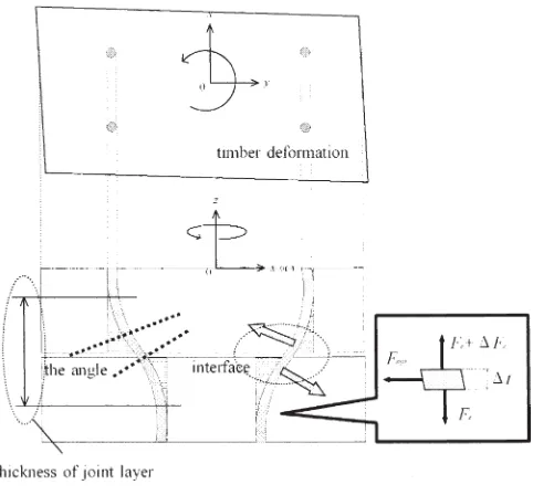
of a slice of the bar between two cross sections attached to rigid plate. To simplify, it is thought that the BCLJ can be divided into the three parts of joint layer, side member, and main member, as in Fig. 1.
In the case of the number of rivets in steel frame struc-tures, it can, according to Goodier’s hypothesis,10
be as-sumed that the distribution of shear force of rivet is governed by Coulomb’s law. It can be modelled as a slice of the joint layer between two cross sections attached to the rigid plate – joint layer assembly. Figure 2 shows the thick-ness can be assumed to be a slice, the angle at the arbitrary point through the longitudinal direction of rivet is constant, and the members made of steel can be assumed to be rigid bodies. On the other hand, it is questionable to apply Coulomb’s law to BCLJ without a circular bolt arrange-ment. If BCLJ has a joint layer, the thickness of the BCLJ cannot be assumed to be a slice. The angles at the arbitrary point through the longitudinal direction of rivet are differ-ent, and members made of timber cannot be assumed to be rigid bodies, as in Fig. 3.
Ohashi and Sakamoto11
pointed out that timber mem-bers could not be assumed to be a rigid bodies, but should, perhaps, be assumed to be elastic bodies. Ono et al.12 also pointed out that the bolts of the BCLJ may not work as supposed in conventional theories8,9
without the circular arrangement of bolts.
To promote the use of large-scale wooden frame struc-tures in Japan and other countries, it is important to predict their actual characteristics correctly. In this study, a manual design method is developed in terms of yield strength and rotational stiffness of BCLJs by considering timber defor-mation, and not using Coulomb’s law, but rather using Saint Venant torsion theory.
Theory
is subjected to a bending moment M, and a coupling mo-ment M, which forms a torque M to resist the bending deformation of bolts. The joint layer, assuming bolts as a joint layer, is twisted by the torque M. It can be thought that BCLJ has three deformation factors: shear deformation of
timber, bending deformation of timber, and bending defor-mation of bolts, as in Fig. 5. Shear forces of bolts are actually complicated mechanisms that consist of member deformation at the panel zone, and bending deformation of the bolt, as in Fig. 6. To derive a simple design method, the following hypotheses are set:
BCLJ can be divided into the three parts of joint layer, side member, and main member, as shown in Figs. 1 and 2.
Pi would be composed to the shear force of bolts (PRBi) due to joint layer, and the shear force of bolt (PjTBi) due to the member deformation at panel zone, as in Fig. 6.
The shear force of the bolts is decomposed to the shear force due to shear force and the applied shear force due to moment.
Joint layer
There are two theories on static torsion, shown in Fig. 7. The stress distributions, according to Coulomb’s law,10
are in proportion to the distances from the rotational centers. The stress distributions, according to Saint Venant’s torsion theory,13
are not in proportion to the distances from the rotational center. The stress distributions of shorter sides are larger than those of longer sides, as shown in Fig. 7.
In this study, Saint Venant’s torsion theory is considered, because BCLJ that have slender bolts cannot meet Goodier’s hypothesis, i.e., the panel zone is assumed to be a rigid body, or bolts do not have the required length. There are still some problems in using Saint Venant’s torsion theory to derive a practical design equation. For example, this theory cannot be calculated without a computer. In addition, it is impossible to explain the load distribution of bolts using this theory, because the mechanisms of BCLJ are not real torsions. Saint Venant’s torsion theory is a target for a continuum. A boundary condition must be sat-isfied at the surface, i.e., normal stress is equal to zero at the surface, as in Fig. 8a. This boundary condition outlines the character of the stress distribution. The highest stress is found at the middle of the sides, and the lowest stress is found at the corner of the sides, as in Fig. 7. In the case of Fig. 1. Modelling of bolted cross-lapped joints (BCLJ)
x
y
0
z
xory
0
Fig. 2. Model of number of rivets of steel frame structures
Fig. 3. Model of BCLJ
BCLJ, normal stress is zero at the outermost bolts. There-fore, it is assumed that the distribution of x and y compo-nents of shear forces are constant at the same distance from the y- and x-axes. The distribution of the x and y compo-nents of shear force is proportional to the distance from the
y- and x-axes, as shown in Fig. 6. The following relationships
exist:
PxRBi xxi x:undetermined coefficient (1)
PyRBi yyi y:undetermined coefficient (2)
The relationship between x and y is determined by Saint Venant torsion theory. In the case of Coulomb’s law,
x and y are the same value, or are determined by geo-metry. According to Timosienko and Goodier,13
it was found that half the torque was due to the x-components of
the shearing stress and the other half to the y-components in Saint Venant torsion theory. In this study, it can also be assumed that the moment due to x-components of shear forces is equal to that due to y-components.
Mtx M Mty M
1 2
1 2
, (3)
Timber deformation
Bending moment M causes two deformations on each mem-ber, i.e., shear deformation of timber and bending
deforma-x
y 0
x
y 0
y 0
Fig. 6. Distribution of shear force of a BCLJ based on proposed theory
Fig. 7. Distribution of shearing stress according to Coulomb’s law and Saint Venant’s torsion theory
tion of timber. Assuming that shearing stress distribution of timber at the panel zone is a constant, and PjSDi is also proportional to the distance from the y-axis, as in Fig. 5.
PjSDi γjxi γj:undetermined coefficient (4)
Considering timber bending deformation at the panel zone, shear stress distribution of timber at the panel zone by M can be assumed to be a constant. Each member is consid-ered as a beam. Using basic beam theory, the following relationship exists: Q M h d x
dx h j
jM j j i i j 3 3
δ
(
)
where, : depth of timber (5)Meanwhile, the center of bolt arrangement is thought to be symmetrical, and the following boundary conditions are possible:
Mj
(
0)
0,δj(
0)
0, and θj(
0)
0. (6)Using these boundary conditions and Eq. 5, δj (xi) can be derived as follows:
δ j i i
j j j
x Mx
h E I
(
)
36 (7)
The load distribution of a bolt due to timber bending at the panel zone is expressed as the product of the bending defor-mation of timber δj(xi) and the semi slip modulus16
Kh90ji of a bolt perpendicular to the grain. From the above, the load distribution PjTBi of a bolt by bending deformation of timber has the following form:
P x K MK x
h E I
j i j i h ji
h ji i
j j j
TB δ
(
)
9090 3
6 (8)
Corresponding to the x-component, the shear force of bolt
PxMi can be expressed as follows:
PxMi PjTBi PjRBi PjSDi (9)
To simplify, a new parameter α is employed;
α x γj α: undetermined coefficient (10)
Pix can be expressed as follows:
PxMi α i
h ji i
x MK x
h E I
90 3
1 1 1
6 (11)
Moment due to x-component must be satisfied:
M i PxMixi
n
1
Â
(12)From Eqs. 11 and 12, by eliminating α, PxMi is obtained:
P Mx x K M
E I h x
x x x xMi i i i n h ji i i i i n i i n 2 1 90
1 1 1 3 4 1 2 1 6
Â
Â
Â
Ê Ë Á Á ÁÁ ˆ ¯ ˜ ˜ ˜˜ (13)and PyMi can be obtained in the same way as PxMi:
P My y K M
E I h y
y y y yMi i i i n h ji i i i i n i i n 2 1 90
2 2 2
3 4 1 2 1 6
Â
Â
Â
Ê Ë Á Á ÁÁ ˆ ¯ ˜ ˜ ˜˜ (14)Here, applied shear force P is assumed to be distributed to each bolt uniformly, i.e.:
P P n i
s (15)
The total bolt load, therefore, contains Psi and PxMi. From the above, Pix and Piy are expressed as:
P P
M n
ix xMi
j (16) P P M n
iy yMi
ψ
(17) where, f P/M, Ψ P/M.
As the component of shear force due to the coupling moment is composed torsion moment, it can be thought that the resultant force Pi consists of Pix and Piy is the shear force of arbitrary bolt at interface between member 1 and mem-ber 2, as in Fig. 5a. The resultant force Pi can, therefore, be simply calculated as:
Pi Pix Piy
2 2
(18) From above, the equation for yield moment of BCLJ (My) is obtained as:
My min
(
Myi)
where M P x y yi yi i i
2 2 (19)
X x x K
E I h x
x x x n i i i i n h ji i i i i n i i n 2 1 90
1 1 1 3 4 1 2 1 6
Â
Â
Â
Ê Ë Á Á ÁÁ ˆ ¯ ˜ ˜ ˜˜ j Y y y KE I b y
y y y n i i i i n h ji i i i i n i i n 2 1 90
2 2 2 3 4 1 2 1 6
Â
Â
Â
Ê Ë Á Á ÁÁ ˆ ¯ ˜ ˜ ˜˜ ψEstimation of rotational stiffness of BCLJ will be derived as follows.
Total energy U at joint part is:
U PS M
E I dxdy Q dxdy
i i j j h i n jM sj h j j 1 2 1 2 1 2 2 0
1
Ú
0
JM
From Eqs. 20, 21 and basic beam theory, the rotational stiffness of BCLJ (R) is as follows:
R P P
K G b t h G b t h
h EI h E I xMi yMi i i n 1 1 1 48 48 2 2
1 1 1 1 2 2 2 2
1 1 2 2 2 2 s Ê Ë Á ˆ¯˜
Â
(22)In the case of ignorance of timber deformation, Eq. 19 can be expanded as:
My min
(
Myi)
where M P x x y y yi yi i i i n i i i n 2 2 1 2 2 2 1 2
4Ê
Â
4Â
Ë
Á ˆ¯˜ ÊËÁ ˆ¯˜
(23)
In the case of ignorance of timber deformation, Eq. 22 can be simplified as:
R x K x y K y i i i n i i n i i i n i i n 4 2 1 2 1 2 2 1 2 1 2 s s
Â
Â
Â
Â
Ê Ë Á ˆ¯˜ ÊËÁ ˆ¯˜ (24)In the case of cross-grained members, Ksi would be assumed as a constant value Ks.8,9
Thus, Eq. 24 can be simplified as:
R
K x y
x y i i n i i n i i n i i n 4 2 1 2 1 2 1 2 1
s
 Â
Â
Â
(25)
Materials and methods
Specimens
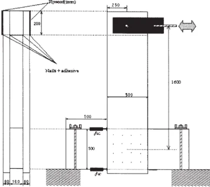
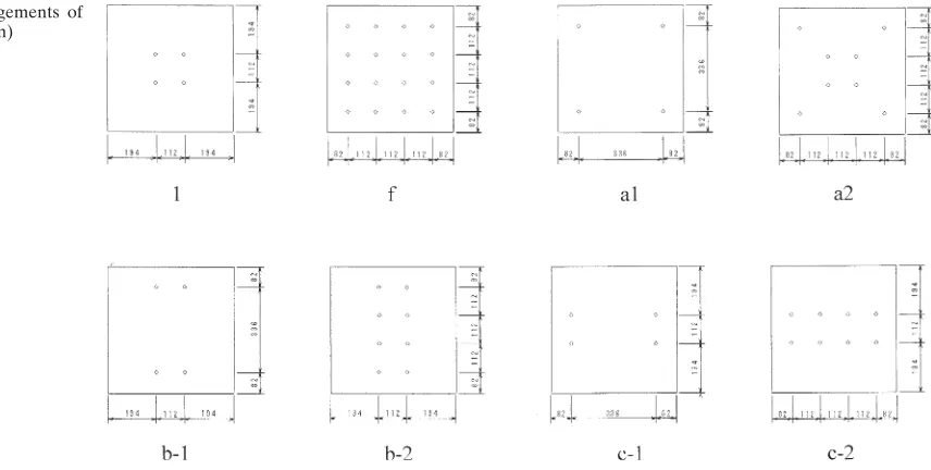
Figure 9 shows BCLJ specimens used in this study. Each BCLJ specimen consists of a column (160 500 1500 mm) and a pair of beams (80 500 2000 mm). They were joined with bolts and formed a T-shaped assembly. Bolts were arranged in a rectangle or square with the num-ber of bolts ranging from 4 to 16, see Fig. 10. Each bolt had
a diameter of 16 mm, and a length of 32 mm. Clearance between the bolt and the predrilled hole was 1 mm in all specimens. Columns and beams were made of Douglas-fir glulam having JAS grade of E105 – f 300, with an average moisture content of 11%, and mean density of 456 kg/m3.
Cyclic load14
was applied, as in Fig. 9. Moment (M) and rotational angle of BCLJ (θ) are defined as follows:
M 1 85.
(
m)
P (26)
θ
δ# δ#
1 2
500 (27)
where P is applied load (kN), and δ#1 and δ#2 are relative displacement (mm), shown in Fig. 9.
Results and discussion
Verification
Material properties for numerical calculation were adopted from previous studies,15,16
except for the bearing properties of bolts. The bearing property was calculated using the modulus of elasticity of the laminas. The slip modulus and the yield strength of single bolted joints were calculated using the proposed equation,17
as follows: Slip modulus Ksi h i h i h i h i K K K K 1 1 2 2 (28) Where; K λ γ λ λ λ λ λ hj
ji s ji ji ji ji ji ji ji ji
ji ji ji ji
EI t t t t
t t i 2 3 2 2
(
)
(
sinh cosh sin cos)
cosh sin
Table 1. Definitions of symbols
Symbol Definition
bj Width of member j
di Diameter of i-th bolt
Ej Modulus of elasticity in member j EIsi Bending stiffness of i-th bolt Gj Shear modulus of member j
hj Length of member j
i i-th bolt
Ij Moment of inertia of member j j 1 is main member, 2 is side member
Kh90ij Semi slip modulus of i-th bolt perpendicular to the grain in member j Khji Semi slip modulus of the i-th bolt in member j
kji Bearing constant of i-th bolt in member j Ksi Slip modulus of the i-th bolt
Ks Slip modulus
M Working moment at panel zone
Mj(x) The function of moment distribution in member j Mtx x-component of M
Mty y-component of M
Mv Yield moment of BCLJ
Mvi Yield moment calculated by i-th bolt n The number of bolt in BCLJ
P Applied load
Phbji Yield strength calculated assuming bolt bending yield of i-th bolt in member j Phwji Yield strength calculated assuming wood bearing yield of i-th bolt in member j Phvji Yield strength of i-th bolt in member j
Pi Shear force of i-th bolt
Pix x-component of shear force of i-th bolt Piy y-component of shear force of i-th bolt
Pji Shear force of i-th bolt due to both coupling moment and shear force in member j
PxMi The component of shear force of i-th bolt due to moment in member j PvMi The component of shear force of i-th bolt due to moment in member j PRBi Shear force of i-th bolt due to torsion of joint layer
PxRBi x-component of shear force of i-th bolt due to torsion of joint layer PyRBi y-component of shear force of i-th bolt due to torsion of joint layer PjSDi Shear force of i-th bolt due to timber shear deformation at panel zone of in
member j
Psi Shear force of i-th bolt due to applied shear force
PjTBi Shear force of i-th bolt due to timber bending deformation at panel zone in member j
Pvj Yield strength of i-th bolt in member j R The rotational stiffness of BCLJ
ri Distance between the centre of bolt arrangement and i-th bolt Si The slip of i-th bolt
tji Length of the i-th bolt in member j U Total energy at joint part
xi The distance from x-axis in i-th bolt yi The distance from y-axis in i-th bolt
Z Section modulus
α Undetermined coefficient x Undetermined coefficient y Undetermined coefficient
γj Undetermined coefficient in member j γsj Shear strain of member j
δ#1 Relative displacement between timber and beam in experimental work in Fig. 9
δ#2 Relative displacement between timber and beam in experimental work in Fig. 9
δj(x) The function of bending deformation of timber at x in member j θ Rotational angle of BCLJ
θj(x) The function of the angle of beam at in member j λji Coefficient of i-th bolt in member j
σsyi Yield stress of steel in i-th bolt
σyji Bearing yield stress of i-th bolt in member j
QjM The average shear stress of member at panel zone due to moment worked at panel zone in member j
j Coefficient
λji
ji i
i
k d EI
4
4
(
)
sYield strength
Pyi min
{
Phy i1 in maim member, Phy2i in side member}
(29) Where;
P
σ σ
hy hwji hbji
hbji
ji syi i i
hji hwji
hji yij
ji
i ji
P P
P k Z d
K P
K k
Z d
min ,
.
{
}
0 6
6
3
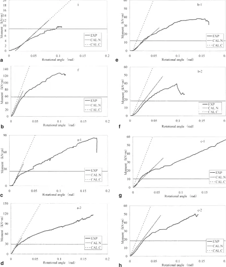
The comparisons between theoretical calculations and experimental results, shown in Fig. 11, shows that rotational stiffness and the yield moment of BCLJ can be precisely predicted by using the proposed theory without type 1. In the case of specimen 1, the practical values of yield moment and rotational stiffness are lower than the calculated values. It was considered that only a few bolts worked, because the distance between the bolt and rotational shaft in specimen 1 was much smaller than that of the other specimens. The influence of clearance is governed by the distance between the bolt and rotational shaft. Therefore, the mechanism of specimen 1 is different from the supposed mechanism of the proposed theory.
For rotational stiffness, the estimated values by conven-tional theory4
are about two times higher than the experi-mental results for the rectangular bolt arrangement, as in Fig. 11. The difference of values between conventional
theory and experimental data is not thought to be a result of the clearance between the bolts and the predrilled holes, but due to shortcoming of Saint Venant’s torsion theory. If the clearance does have any influence, such a difference should also exist in the case of the square bolt arrangement.18,19
Relationship between proposed theory and conventional theory
In the case of symmetrical arrangement of bolts on both the
x-axis and y-axis, Eq. 30 remains consistent, i.e.:
i xi y
n
i i
n
2
1
2
1
Â
Â
(30)Therefore, Eq. 25 can be simplified as:
R K i xi
n
2 2
1
s
Â
(31)Using Eq. 30, conventional theory can be expressed as:
R K rii
i n
s
2
1
Â
(32)where;
ri xi yi
2 2 2
In the case of a symmetrical arrangement of bolts on both the x-axis and y-axis, Eq. 32 can be simplified as:
R K i xi
n
2 2
1
s
Â
(33)y-axis, rotational stiffness determined from the proposed theory has the same value as that from conventional theories.
Conclusions
A new approach was developed to estimate the perfor-mance of bolted timber joints in a practical manner, rather than based on computer simulation. From the theoretical
and experimental results, it can be concluded that the rota-tional stiffness and yield moment in bolted cross-lapped joints can be precisely predicted by the proposed theory. In the case of rectangular bolt arrangement, the rotational stiffness calculated using conventional theory was about two times higher than the experimental results. Therefore, it is not reasonable to use the theory rooted to Coulumb’s law for estimating rotational stiffness in the case of a rectan-gular arrangement of bolts.
Fig. 11a–h. Comparison between experimental results and estimated values using proposed theory in BCLJs for different bolt arrangements. EXP, experimental result; CAL.C, rotational stiffness calculated by
conventional theory, Eq. 32; CAL.N, rotational stiffness and yield moment calculated by our proposed theory, Eqs. 22 and 19
a
b
c
d
e
f
g
References
1. Leijten AJM (1998) Reinforced joints with expanded tube fasten-ers. In: Densified veneer wood reinforced timber joints with expanded tube fasteners. Delft University Press, Delft, pp 57–96 2. Leijten AJM (1988) Steel reinforced joints with dowels and bolts.
In: Proceedings of International Conference on Timber Engineer-ing, Washington, vol 2, pp 475–488
3. Haller P, Chen CJ, Natterer J (1996) Experimental study on glass fibre reinforced and densified timber. In: Proceedings of Interna-tional Wood Engineering Conference, New Orleans, USA, vol 1, pp 308–314
4. Haller P (1999) Semi-rigid timber joints – structural behaviour, modelling and new technologies. Final Report of Working Group on Timber Joints
5. Leichti RJ, Tjahyadi A, Bienhaus A, Gupta R, Miller T, Duff S (2002) Design and behaviour of frictio dampers for two-dimensional braced and moment-resisting timber frames. In: Proceedings of World Conference on Timber Engineering, Shah Alam, Malaysia, vol 2, pp 267–274
6. Larsen HJ (1996) Glass fibre reinforcement of dowel-type joints. In: Proceedings of International Wood Engineering Conference, New Orleans, USA, pp 293–302
7. Rodd PD (1996) Resin injected dowels in moment transmitting joints. In: Proceedings of International Wood Engineering Confer-ence, New Orleans, USA, pp 169–176
8. Racher P (1995) Moment resisting connections In: Timber engi-neering STEP 1. Centrum Hout, Almere, pp C16/1–C16/11
11. Ohashi Y, Sakamoto I (1989) Study on laminated timber moment resisting joint. In: Proceedings of the Second Pacific Timber Engi-neering Conference, Auckland, New Zealand, vol 2, pp 37– 42
12. Ono T, Ando K, Itoda H, Kato Y (2001) Study on stiffness and ultimate strengths of drift-pin joints of glue-laminated wood mem-bers (in Japanese). J Struct Constr Eng 536:101–106
13. Timoshenko S, Goodier JN (1951) Torsion. In: Theory of elasticity. Kogakuaha, Tokyo, pp 258–263
14. The Building Center of Japan (2002) The building letter. 443:27–32 15. Komatsu K, Karube M, Harada M, Fukuda I, Hara Y, Kaihara H (1996) Strength and ductility of glulam portal frame designed by considering yield of fasteners in part. In: Proceedings of Interna-tional Wood Engineering Conference, New Orleans, USA, pp 523– 529
16. Architectural Institute of Japan (AIJ) (1995) Moment resisting joints (in Japanese). In: Structural design note for timber struc-tures. Maruzen, Tokyo, pp 184–221
17. Noguchi M, Komatsu K (2003) New proposal for estimating method of stiffness and strength in the bolted timber-to-timber joints and its verification by experiments (in Japanese). Mokuzai Gakkaishi 49:92–103
18. Tsuchimoto T (2002) Stochastic estimation of deflection properties on portal frames jointed by bolts with initial clearance. In: Proceed-ings of World Conference on Timber Engineering, Shah Alam, Malaysia, vol 2, pp 485–493