Labview Based Trucks Overload Detector And
Controlling
Dr. T. Kalavathi Devi, V. Selva Vignesh, V. Shrinithi, R. Tharen
Abstract: Trucks moving beyond legal mass limits increase the risk of traffic accidents and destruction to the assembly. They also result in out-of-line conflict between transport modes and societies. It is vital for a truck to have a standard weight measures guideline. Present ly, technologies are being developed for efficient overload screening without considering the truck weight and enforcement. The transportation is a vital part of a society for a secured transportation system. The transportation is a vital part of a society for a secured transportation system. Even though there are many factors which cause accidents but a majority of them are caused because of overloading. First of all, the maximum weight that a truck can carry is defined by the manufactures at the time of production unfortunately the drivers overload the vehicle for their convenience. Overloaded vehicles, especially cargo vehicles, causing damages to our roads and affects the economic growth and the damage caused grows exponentially as the load increases. As a result of overloading roads gets damaged and leads to higher repair costs and maintenance which in turn places an additional burden. If the problem of overloading is not controlled, this cost has to be carried by the road user, which will require significant increases in road user charges such as the fuel expenses, vehicles toll fees, and fine by RTO (Rto mention just a few. In this project, the load carried by the vehicle is measured by using inbuilt weighing mechanism and it is continuously monitored. Controller is used as a data acquisition to monitor and send the data to the vehicle dash-board. The objective is to reduce the accidents caused by overloading of trucks and to find out the loss of goods during transportation.
Keywords: Ignition, Load Cell, LabVIEW, Overload, Weight
————————————————————
1
INTRODUCTION
The objective of the proposed work mainly concentrates in prevention of damage of roads by humans because of overloading and unauthorized, unlicensed driving. Road transport plays a very important role in every part of world.
Roads and streets are one of the most important means of transportation in the country. It is used by almost everyone on a daily basis. Besides the fact that roads are provided for the benefit of the common people, they also play a significant role in promoting economic growth and the living standards of the population. According to the National Highway Traffic Safety Administration (NHTSA), there were 3,900 fatalities and 104,000 individuals injured as a result of truck crashes in 2012. One common reason for catastrophic injuries in truck Collisions are due to driver's loss of control of an overweight or overloaded truck. Both the central and state laws comprise weight limitations for trucks carrying goods. Some states permit the trucks to go beyond the specified weight, however with a special constraint. If the rules concerning weight and over burdening are ruined, it consequences in a serious truck accident. The victim or victims can carry a lawsuit for indemnities. It has been found that legally loaded cargo vehicles cause a relatively small amount of damage to road pavement structures, as opposed to overloaded cargo vehicles which are responsible for approximately 70% of the damage to the road network and accidents. The fines currently imposed by the courts on those convicted for heavy vehicle overloading are in most cases negligible in comparison with
the damage caused to the roads and are quite clearly in effective Furthermore, overloaded vehicles become a traffic hazard, especially regarding the heavy vehicle’s braking system and involving additional braking distance. This situation is aggravated by steep downhill slopes and sharp curves. On steep uphill gradients, the slow moving heavy vehicle causes traffic disruption. When a truck is overloaded or overweight, the truck's performance gets degraded. For example, the vehicle which is overloaded drives an incline or slope at a faster rate than the expectation of the driver. It may require additional braking force to control or stop the vehicle. Additionally, the freight is more probable to change, which ends in the improper distribution of loads. Loads have to be properly distributed on the truck so that no single axle is overloaded, causing the truck to be unbalanced. Improper distribution of load is more likely to lead to rollover accidents or multi-vehicle accidents and also it can lead to items falling off the truck and causing a crash. Trucks that are not properly loaded or balanced may also exceed their weight limit, particularly while traveling on inclines, resulting in a tire blowout, a rollover inconsiderate overloading. If the problem of overloading is not controlled, this cost has to be carried by the road user, which will require significant increases in road user charges such as the fuel expenses, vehicles license fees, and toll fees to mention just a few. Overloading is a safety hazard that leads to unnecessary loss of life, also the rapid deterioration of our roads, resulting in increased maintenance and transportation. Thus, overloading a vehicle incorporates so many problems that results in loss of life, road and vehicle damage. This proposed idea suggests suitable measures to minimize.
2
LITERATURE
REVIEW
2.1 Existing Method
Customary weight limit implementation measures are fixed weighing. It was the only method approved by the legal metrology up to the mid-1990s. Weigh bridges, axle scales and wheel are used to measure gross vehicle weight and wheel or axle loads. If axle scales are used, the gross vehicle _________________________________
• Dr. T. kalavathi Devi, Kongu Engineering College, India, PH-9942155300. E-mail: [email protected]
weighing devices are of three types. The static systems are permanently attached in the roadway, usually in concrete frames or stages. It is the common strategy for all weigh bridges and some wheel and axle scales. Semi-portable systems, make use of fixed grooves and path installations (electricity supply, connection to the weight recorder, etc.), that is done with transferrable scales which are connected only during the weighing schedules.
2.2 Vehicle Overloading
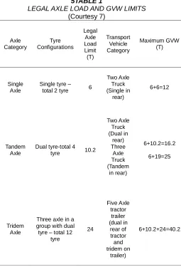
The Central Motor Vehicle Rules as indicated in Table 1, stipulates that the maximum gross vehicle weight (GVW) should not be greater than the sum total of all the maximum safe axle weight put together on the vehicle which is subject to restriction. The allowable axle loads indicated by the government of India / competent authority is mentioned as Legal Axle Load Limit (LALL). However, Khana SU, Ayubb T, Qadira and Mulyun. A.Parikesit.D (2010) have emphasized on detecting and monitoring the load on the vehicle but in they emphasized mainly on controlling the ignition of the vehicle to prevent overloading in vehicles. It is found that the actual loads supported by the transporters rarely follow these stated limits and desire to overload their vehicles. This includes the different technology trucks, truck-trailer, tractor-trailer, etc. with High Brake Horse Power (HBHP). The vehicle overloading may be controlled by measuring the load using roadside weigh bridge station. A. Polus (1984) if overloading is controlled, number of vehicle shall be increased assuming that same weight for different goods will be transported from one place to another place to fulfill the demand and supply of these particular goods. If loading is controlled, the VDF value of each cargo vehicle is altered or reduced. The process of evaluating the revised traffic is shown in the case study described in the following section. For the purpose of adjustment, a total of four cases have been considered. The four scenarios are (1) actual case, (2) at legal load, (3) more than 20 % legal load (4) more than 30 % legal load. Number of actual vehicles weighed during axle load survey and revised number considering different axle load controls are shown in Table 1. The typical problems connected with the involvement of trucks in road accidents have been discussed. Some 600 accidents related to runaway trucks and presented several contributing factors, among which were driver error, equipment failure, and lack of experience with mountain driving. A study by McGee on accident types and contributing factors indicated that truck-accident rates varied inversely with truck weight. Among the effects surveyed were those of roadway geometry, roadside features, and wide loads [3] who analyzed accident characteristics by vehicle weight, discovered that larger trucks were more likely to be involved in single-vehicle crashes than were cars or smaller trucks. Their study also suggested that some truck drivers.
5TABLE 1
LEGAL AXLE LOAD AND GVW LIMITS (Courtesy 7) Axle Category Tyre Configurations Legal Axle Load Limit (T) Transport Vehicle Category Maximum GVW (T) Single Axle
Single tyre – total 2 tyre 6
Two Axle Truck (Single in rear) 6+6=12 Tandem Axle
Dual tyre-total 4 tyre 10.2
Two Axle Truck (Dual in rear) Three Axle Truck (Tandem in rear) 6+10.2=16.2 6+19=25 Tridem Axle
Three axle in a group with dual tyre – total 12
tyre 24 Five Axle tractor trailer (dual in rear of tractor and tridem on trailer) 6+10.2+24=40.2
TABLE 2
AXLE LOAD SURVEY CONSIDERING OVERLOADING (Courtesy 7)
Developed an algorithm that describes the rubrics for mass and dimension of the truck with mechanical suspension. While performing the simulations the condition of the engine checked. The relation taken between the vehicle load and the body height. When the overload condition exceeds the set limit up to 20% warning is given to the power cord of the starter and power supply line of the injectors.
3
LARGE
TRUCK
COMBINATIONS
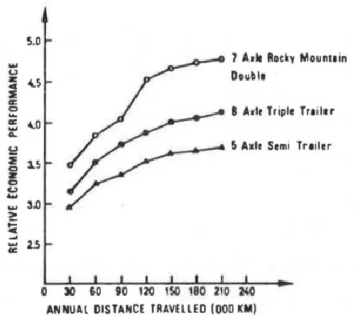
Long combinations of trucks have, for some time, constituted a subject of much controversy. Alongside the economic advantages of these vehicles (e.g., a saving in manpower), there exists. The analysis of the operating costs of heavy-truck combinations in western Canada and evaluated their relative efficiencies. The economic performance [7] of any given truck combination can be compared to a 2-axle truck (or to any other base), and its relative value are obtained Fig 1. Shows the relative economic performance of various heavy loaded-vehicle combinations for a given annual mileage, based on payload-to-cost relationships. One of the most common types of accidents in which a high truck involvement may be expected is the rear-end collision. As can be seen, all categories of rear-end accidents account for as much as 35 percent of all truck-involved accidents. Trucks are exposed to this type both at intersections and on grades. At intersections, the problem stems from the stopping difficulties of trucks. On upgrades, trucks are prone to being rear-ended by overtaking vehicles; on downgrades, a truck may rear-end a slower-moving vehicle. Another type of accident in which one may expect a high involvement of trucks is a side-to-side collision. These are created on account of the dimensions of trucks and their special difficulties on curves.
Fig 1. Relative Economic Performance of Various Heavy-Vehicles
(Courtesy 7)
4 METHODOLOGY
OF
TRUCKS
OVERLOAD
DETECTOR
AND
CONTROLLING
Fig 2. Block Diagram of Trucks Overload Detector and Controlling
The process and the detailed description of how trucks overload detector and controlling is explained. Fig 2 represents the block diagram of Trucks Overload Detector and Controlling. It consists of load cell to measure the weight of the truck along with the permissible load. The ignition circuit to start the engine. The MEMS sensor that is used to find out whether a misplaced or mishandled baggage or container is loaded in the trucks, and if found then the ignition of engine triggers to stop step by step and the sensor alerts the driver by glowing an alarm. Alcoholic sensing sensor that detects the condition of the driver to alert the owner of the truck.
Vehicle Type
No.of vehicle actually weighted
No.of vehicle at legal load
No.of vehicle at 20% above
legal load
No.of vehicle at
30% above legal load
2-Axle
truck 219 251 218 206
3-Axle
truck 166 193 166 156
4- Axle
truck 113 131 113 106
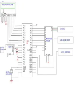
Fig 3. Circuit Diagram of Trucks Overload Detector and Controlling.
Fig 3 depicts the circuit diagram of Detector and Controlling, a constant 12V supply is given by the lead acid battery. The 12V supply from the battery is fed to voltage regulator (5V) which is the input voltage required for microcontroller. For actuating relay and motor another 12V supply is taken separately from the battery. The measured load value from the load cell is amplified with the help HX711 load cell amplifier and then given to the controller and the load value is displayed using LCD. Current scenario of India, most of the road accidents occurs due overloading of trucks. If an accident occurs in a highway it affects the surrounding environments too. In order to reduce to the above problem this idea is proposed. For example, consider a truck [4] that has a maximum capacity of 20 tonnes. If the truck is loaded above 20 tonnes it makes an indication like overloading to the dashboard. When the driver ignites the truck without unloading the goods, the engine will not start and the fuel supply to the engine will be cut off. The loading and unloading of the goods should be done by keeping ignition in ON condition. This concept can be applied to mini auto, mini trucks thereby avoid cheatings too (consider the person A is working under B.B wants to transport his goods from Salem to Chennai. Without the owner’s knowledge if A loads the goods in the truck in between any of these two places, immediately B knows that.) The main objective of this is to evade such catastrophe by overloading of trucks which in turn leads to mishap and contretemps in hilly regions. Due to overloading of goods, engine losses its total pulling power which leads to break down. As a consequence, finally the driver losses his total controls. The area of application in Ghats’s road most of the accidents are occurring in this region only due to overloading.
5 FLOW
CHART
FOR
TRUCKS
OVERLOAD
DETECTOR
AND
CONTROLLING
Fig 4. Flow Chart of Trucks Overload Detector and Controlling
The Flow chart of Trucks Overload Detector and Controlling is shown in Figure 4. The load on the vehicles is detected by the load cell module. The output in Millivolts is given to the microcontroller through the interfacing module. When the load is below 95% it is under safe limit, so the relay remains closed and the engine ignition takes place. When the load is above105% the safe limit got exceeded, so the relay gets opened and restrict the battery supply to self-start motor. So, the ignition does not occur. And also it will detect if driver consumed alcohol or not. If Driver consumed alcohol the information sends to nearby RTO (Regional Transport Officer) and to the truck Owner through GSM technology.The MEMS sensor detects any misplacement of goods in the trucks. If it detects immediately it sends the information to trucks Dashboard. The above mentioned logic for trucks overload detector and controlling was coded in Embedded C language.
6 SETUP
OF
TRUCKS
OVERLOAD
DETECTOR
AND
CONTROLLING
Fig 6. Electronic circuit of Trucks Overload Detector and Controlling
Fig 7. Hardware part of Trucks Overload Detector and Controlling
The circuit consists of Load cell, Interface module, Microcontroller, liquid crystal display, relay, Direct Current (DC) motor.12V Lead acid battery is used as a power supply. From battery a constant 12V supply is provided.
The voltage regulator (5V) is placed to regulate 5V input required for the microcontroller. The Electronic circuit of Trucks Overload Load Detector and Controlling is shown in Figure 5. The circuit consists of Load cell, Interface module, Microcontroller, liquid crystal display, relay, Direct Current (DC) motor. 12V Lead acid battery is used as a power supply. From battery a constant 12V supply is provided. The voltage regulator (5V) is placed to regulate 5V input required for the microcontroller. When the key module is turned ON, the battery supply is connected and the LCD displays the load status. If the load is below the set point the relay remains closed and the motor runs. When the load exceeds the set point the relay gets opened and the motor will not run. The Hardware model of Trucks Overload Load Detector and
model of the truck and chassis is made by using PVC pipe and under chassis plywood is placed for mounting the load cell to mimic a truck. When the load is placed above the load cell, it displays the weight of the load in g/kg.
6.1 SIMULATION SETUP OF TRUCKS OVERLOAD DETECTOR AND CONTROLLING
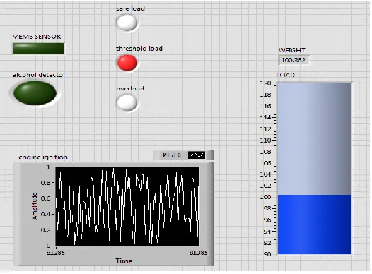
In order to control overloading of the passenger vehicle, an automatic control system based on LabVIEW for overloading passenger vehicle was designed. The system hardware is mainly composed of the data acquisition (DAQ), sensor working control circuit; Sensor circuit mainly consists of the load cell, interface module dc motors, MEMS sensor, MQ6 Gas sensor and processing circuit. The DAQ control is used to control the sensors by stopping the ignition to the Engine (Figure 6). At the bottom of the axle, the detection system has load cell sensors mounted near the leaf springs. When the load gets loaded to trucks, load cell detects the weight and it transmits to the DAQ. The rated truck capacity was stored and coded in the LabVIEW program. When it is overloaded, the control unit controlled battery ignition system to stop ignition. So, the vehicle will not start, which controlled the overloading. Thereby it also detects the conditions whether the driver consumed alcohol or not and whether the goods are misplaced in the trucks. If it detects any of these conditions, immediately information will be send to the owner of the truck and as well as RTO. The ignition circuit of the key module is shown in the figure 8. It has three states which comprises of Accessories, ON and Start and it also has a relay which connects the supply between battery and self-start motor to ignite the engine. The ignition circuit of the key module is shown in the figure 8. It has three states which comprises of Accessories, ON and Start and it also has a relay which connects the supply between battery and self-start motor to ignite the engine.
Fig 8(b). Simulation setups of trucks overload detector and controlling in LabVIEW
Fig 9. Ignition Circuit of Key Module
7
RESULTS
AND
DISCUSSION
The results and discussion for the Trucks Overload Detector and Controlling. The Table 3. Depict the results of the working of load cell and motors based on the weight values. The result and analysis of Trucks Overload Detector and Controlling is shown in Table 3. When a mobile phone is placed over the load cell it measures 200 g, as it is less than the set point the ignition occurs. Likewise, while placing Water Bottle and Books and 1 Kg Dumbbells the status remains the same and ignition occurs but while placing 3 Kg and 5 Kg Dumbbells the load falls above the set point so the ignition does not occur. The observations of Trucks Overload Detector and Controlling based on load cell shows that the load cell measures the load in the truck and compare it with the set point (load) and also checks whether the driver consumed alcohol or not and also the placement of goods. If the load is below the set point (load) the motor starts to run and the engine ignition occurs. And when the load is above the set point (load) the engine ignition does not occur until the excess weight is un-mounted. The observations of Trucks Overload Detector and Controlling based on load cell shows that the load cell measures the load in the truck and compare it with the set point (load) and also checks whether the driver consumed alcohol or not and also the placement of goods. If the load is below the set point (load) the motor starts to run and the engine ignition occurs and when the load is above the set point (load) the engine ignition does not occur until the excess weight is un-mounted.
TABLE 3
RESULTS AND ANALYSIS OF TRUCKS OVERLOAD DETECTOR AND CONTROLLING
8
CONCLUSION
In order to control overloading of the passenger vehicle, automatic control system for overloading passenger vehicle was simulated using LabVIEW. The Sensor circuit mainly consists of the load cell, interface module dc motors and processing circuit. In this project, the load cell detector and controller module was set up at the bottom of the Axle above the chassis. The rated truck’s capacity (2.5 Kg) was coded in the microcontroller. When the load is within the limit, the engine will normally ignite. When the load exceeds the rated capacity, the ignition will not occur. This prevents overloading and contributes toward more compliance with mass regulation. It helps in reducing the number of overloaded trucks, which contributes to the more efficient and more effective use of roadways. A reduction in overload truck is also conductive to a reduction in crashes and serious damage to people’s lives and property.
9
FUTURE
SCOPE
The overloading of a truck, such as a single-axle and tandem tractor–trailer combinations, presents problems, both to the owners/operators and to governmental regulatory bodies. The owner/operator must be assured that the loaded truck is not overweight, either because of truck safety per se or by reason of exceeding road weight safety regulations. By using IoT, load cell kept below will be able to measure the weight of the goods and using the Wi-fi module connected with controller board coded with Embedded C program the weight measured will be transmitted to the internet server. Using the mobile app along with the channel id provided the user can monitor the weight carried by the vehicle. So, the excess weight also can be monitored and cautioned. Here by also placing the GPS (Global Position Satellite) in the vehicle position can also be monitored by the user along with weight in app which
S.
No Load
Load in Kg
Key State Load Status & consump tion of alcohol Igniti on State State 1 State 2
1 Iron
Weight 200 g ON ON
Normal Load & not consume d alcohol Igniti ng
2 Iron
Weight 700 g ON ON
Normal Load & not consume d alcohol Igniti ng 3 1 Kg Dumbbell s
1 Kg ON ON
Normal Load & Misplace d of goods Not Igniti ng 4 3 Kg Dumbbell s
3 Kg ON ON
Overload &consum ed alcohol Not Igniti ng 5 5 kg Dumbbell s
5 Kg ON ON
provides additional security to vehicle. Shows that the load carried by the truck is displayed in the webpage and it is also viewed by owner through mobile application. The overload indication, of truck is notified in driver’s front panel.
REFERENCES
[1]. SU Khana, T Ayubb and A Qadira,‖ Effect of overloaded vehicles on the performance of highway bridge girder‖, a case study, 77,95-105, 2014
[2]. M Freitas, ―A Review of Accident Research I.n-volving Truck Size and Weight, public roads‖, 46(2), 46-50, 1982
[3]. L.S.S Lohman, P.F Waller, ―Trucks An Analysis of Accident Characteristics by Vehicle Weight‖, Highway Safety Research Center, University of North Carolina,, 65-71, 1975.
[4]. T. Kalavthi Devi, V.Selva Vignesh, ―Trucks overload Detector and controlling‖, International Journal of Distributed Computing And Technology,(5)1,15-20, 2019.
[5]. A Mulyun and D Parikseit, ―Analysis of Loss Cost of Road Pavement Distress due to Overloading Freight Transportation‖, Journal Of the Eastern Asia Society for Transportation Studies, 8, 90-98, 2010.
[6]. Polus, ―An Economic Evaluation of Large Truck Combination‖, The Logistics and Transportation Review, 19(4),337-350, 1984.
[7]. R.A Wolf, ―Truck Accidents and Traffic Safety‖, Society of Automotive Engineers,65-7,1968..
[8]. Liu Yanling, Liu Zhenhua, ―An Optimized Method for Dynamic Measurement of Truck Loading Capacity‖, 3rd IEEE international conference on Intelligent transportation Engineering (ICITE),3-5, 2018.