80
Contouring Control of Non-Minimum Phase
XY Table System using Trajectory ZPETC
Michael Jackson Patrick, Norlela Ishak, Ramli Adnan
Abstract— Non-minimum phase (NMP) model is a discrete-time model obtained from small or reducing sampling-time of open-loop input and output experimental data. The classical feed-forward controller design of this model using inverse of the closed-loop transfer function would produce an unstable tracking control. This is due to phase and gain errors that caused by NMP zero. Thus, zero phase error tracking controller (ZPETC) strategy was introduced to encounter this NMP zero problem. Simulation and real-time controls on NMP XY Table system shows that the overall tracking performance for circular contour is significantly improved.
Index Terms— Non-minimum phase, Discrete-time system, Feed-forward control, Feedback control, Contouring control, ZPETC, Pole-placement method,
————————————————————
1 I
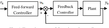
NTRODUCTIONXY Table has been widely used and important part of many computer numeric controlled (CNC) processing facilities, e.g. the work feeder of CNC lathe, CNC milling and drill press, the work table of laser processing, welding, dispenser, bonding, packing, drilling, laser cutting and painting [1]. In general, XY Table is composed of X-axis and Y-axis motion mechanism where each motion axis is driven by individual actuator such as DC servomotor through high precision ball-screw. In tracking or contouring control system, perfect tracking control (PTC) with zero tracking and contour errors is desired, and has been widely studied in [1-12]. PTC can be achieved by introducing a feed-forward controller that act as an inverse of system closed-loop transfer function, cancelling all poles and zeros of the closed-loop system as shown in Fig. 1.
Fig. 1 Two-degrees-of-freedom Controller
PTC can provide the overall transfer function of unity between the desired output and the actual output , but, this will be true when the plant is minimum phase (MP). When the plant is non-minimum phase (NMP), the NMP or unstable zero of the plant will become unstable pole to the feed-forward controller transfer function and thus, creating internal instability [2]. In NMP system where one of the zeros located outside the unit circle, PTC could not be implemented as this would result an unstable tracking control. The phase and gain errors that caused by NMP zero are problematic, however, it can be resolved. The most attractive, effective and simple feed-forward controller strategy to encounter this NMP zero problem is the zero phase error tracking controller (ZPETC),
which has been first proposed by Tomizuka [3-4]. The ZPETC strategy has attracted attention many researchers [5-12]. The ZPETC strategy provides the overall tracking system with zero phase error characteristics by successfully eliminates the phase error that caused by NMP zero and has unity gain for low frequencies. Simulation and real-time controls on NMP XY Table shows that the ZPETC strategy can reduce the overall tracking error effectively. This paper was organized in the following manner: Section 2 describes plant model; Section 3 describes reference trajectory; Section 4 describes Trajectory ZPETC; Section 5 describes feedback control; Section 6 is on results and discussion; and finally, Section 7 is the conclusion.
2 P
LANTM
ODELFig. 2 XY Table system
The XY Table system (GoogolTech GXY3030VD4 series) used in this paper is shown in Fig. 2. The NMP plant model was derived from open-loop input-output test. The open-loop transfer function of the plant is approximated using MATLAB system identification toolbox in the form of ARX231 with input-output signals sampled at . The X-axis plant model is given by Eq. (1) and for Y-axis plant model is given by Eq. (3).
————————————————
M.J. Patrick is currently pursuing master in Electrical Engineering in faculty of Electrical Engineering, UiTM, Shah Alam, Malaysia [email protected]
N. Ishak and R. Adnan are with faculty of Electrical Engineering, UiTM, Shah Alam, Malaysia
[email protected] [email protected]
Feed-forward
Controller
Feedback Controller
Plant
81 2.1 X-axis Plant Model
From Eq. (1), the zeros polynomial obtained are
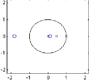
When Eq. (2) is factorized, the locations of zero are at and . This means that the obtained model is a NMP model with one zero situated outside and far away from the unit circle as shown in Fig. 3.
Fig. 3 Poles (X) and zeros (O) locations
2.2 Y-axis Plant Model
From Eq. (3), the zeros polynomial obtained are
When Eq. (4) is factorized, the locations of zero are at
and . This means that the obtained
model is also a NMP model with one zero situated outside and far away from the unit circle as shown in Fig. 4.
Fig. 4 Poles (X) and zeros (O) locations
3 R
EFERENCET
RAJECTORYA circular contour of in radius is shown in Fig. 5. It also shows the reference trajectory of respective individual axis used for plant worktable to move along the circular contour. Both individual axis reference trajectories are sinusoidal wave signal with maximum amplitude of , minimum amplitude of and frequency of 0.1 radians per second. All simulation and real-time controls will be based on this reference trajectory.
Fig. 5 Circular contour and its individual axis trajectory signals
4 T
RAJECTORYZPETC
Referring to Fig. 1 let the closed-loop transfer function (without feed-forward control) is given as
Where represent a -step delay and
Let factorized function into minimum phase
and non-minimum phase factors as
82
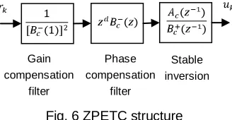
factor is a scaling factor which normalizing the low frequency gain of the overall transfer function between desired outputs to actual output toward unity. As a result, only high frequency gain error that caused by NMP zero remain.
Fig. 6 ZPETC structure
Due to the effect of poles, MP zero and phase cancellation of overall ZPETC structure of Fig. 7, the control structure for simulation purposes can be simplified as given in Fig. 8. Thus, the implementation of tracking control by simulation does not require the whole plant model transfer function. What was needed here was only the gain compensation filter and NMP zeros polynomial of the plant model.
Fig. 7 Overall ZPETC structure
Fig. 8 Trajectory ZPETC structure for simulation control
The implementation of proposed real-time control for Trajectory ZPETC is based on the combination of ZPETC structure of Fig. 6, and feedback control of Fig. 9.
5 F
EEDBACKC
ONTROLThe feedback control in Fig. 9 was designed using pole-placement method.
Fig. 9 Feedback control structure
This method enables all poles of the closed-loop system to be placed at desired location and providing good and stable output performance. The closed-loop transfer function of the feedback system is given by
Where
The feedback control parameters were obtained by solving the Diophantine equation of Eq. (8) to solve for and . The literature on this material can be obtained in [13].
Desired location of pole inside unity circle
In this paper, were used since the tracking required fast response. Let where is a Sylvester Matrix given by
Thus, vector and can be computed from .
Using developed MATLAB m-file, the following parameters were computed
5.1 X-axis Plant Model
D/A
Open-loop XY Table
A/D
To DC servomotor
From rotary encoder Gain
compensation filter
NMP zeros polynomial
Gain compensation
filter
Phase compensation
filter
Stable inversion
Closed-loop transfer function Gain
compensation filter
Phase compensation
filter
83 5.2 Y-axis Plant Model
6 R
ESULTS ANDD
ISCUSSIONThe simulation and real-time controls were done in MATLAB environment. The simulation and real-time results for tracking system without feed-forward controller (pole-placement method) and with feed-forward controller (Trajectory ZPETC) to move in circular contour are shown in Figs. 10-13. It can observe that, the resulted circular contour for tracking system with feed-forward controller is better than tracking system without feed-forward controller. This is explained by loss of coordination and degeneration of circular contour of Fig. 10 and Fig. 12 for tracking system without feed-forward controller. This is due to the phase and gain errors caused by NMP zero, hence, result an unstable tracking control. Fortunately, tracking system with feed-forward controller produces good circular contour as shown in Fig. 11 and Fig. 13. By eliminating phase and has unity gain for low frequencies of 0.1 radians per second, it has confirmed that, Trajectory ZPETC is an effective and simple remedy to the problems caused by NMP zero.
Fig. 10 Simulation result of circular contour for tracking system without feed-forward controller
Fig. 11 Simulation result of circular contour for tracking system with feed-forward controller (Trajectory ZPETC)
84
Fig. 13 Real-time result of circular contour for tracking system with feed-forward controller (Trajectory ZPETC)
From Table 1, tracking performance by simulation control for tracking system with feed-forward controller, the overall tracking root mean square error (RMSE) is better than tracking system without feed-forward controller. The tracking system with feed-forward controller shows better RMSE with 96.40% improvement for X-axis and 95.59% improvement for Y-axis.
TABLE 1: Tracking performance by simulation control
X-axis RMSE (mm) Y-axis RMSE (mm)
Tracking system without feed-forward controller
Tracking system with feed-forward controller (Trajectory
ZPETC)
From Table 2, tracking performance by real-time control for tracking system with feed-forward controller, the overall tracking RMSE is better than tracking system without feed-forward controller. The tracking system with feed-feed-forward controller shows better RMSE with 91.54% improvement for X-axis and 92.36% improvement for Y-X-axis.
TABLE 2: Tracking performance by real-time control
X-axis RMSE (mm) Y-axis RMSE (mm)
Tracking system without feed-forward controller
Tracking system with feed-forward controller (Trajectory
ZPETC)
7 C
ONCLUSIONThe simulation and real-time controls of NMP XY Table system using Trajectory ZPETC are presented. The ZPETC strategy was successfully designed and implemented to NMP XY Table system. In simulation and real-time controls, tracking system with feed-forward controller using Trajectory ZPETC shows good circular contour. This is due to the effectiveness of ZPETC strategy which completely eliminates phase error that caused by NMP zero and displays good tracking performance for low frequency. However, there is difference between simulation and real-time results. This is due to the nature of ZPETC which is sensitive to plant-model mismatch that caused by external disturbance factor such as parameter variations.
A
CKNOWLEDGMENTFaculty of Electrical Engineering, Universiti Teknologi MARA, Shah Alam, Malaysia and all members of Distributed Control System Laboratory are greatly acknowledged.
R
EFERENCES[1] M.J. Patrick, N. Ishak, M.H.F. Rahiman, M. Tajjudin, & R. Adnan, “Modeling and Controller Design for Non-Minimum Phase System with Application to XY-Table,” IEEE. 7th Control & System Graduate Research Colloquium (ICSGRC), pp. 113-118, 2011.
[2] D. Torfs, J. Swevers & D. Schutter,”Quasi-Perfect Tracking Control of Non-Minimal Phase Systems,” 30th Conference on Decision and Control, pp. 241-244, 1991.
[3] M. Tomizuka, “Zero Phase Error Tracking Controllers,”
ASME J. of Dynamic, System, Measurement and Control,”
vol. 109, pp. 65-68, 1987.
[4] M. Tomizuka, “On the Design of Digital Tracking Controllers,” ASME J. of Dynamic, System, Measurement and Control,” vol. 115, pp. 412-418, 1993.
[5] N. Ishak, H. Ismail, M.H.F. Rahiman, M. Tajjudin, R. Adnan & Y.M. Sam, “Tracking Control for Electro-Hydraulic Actuator using ZPETC,” IEEE. 7th Control & System Graduate Research Colloquium (ICSGRC), pp. 94-97, 2011.
85
[7] R. Adnan, A. Manan, Noritawati, M.H.F. Rahiman & M. Marzuki, “Trajectory Zero Phase Error Tracking Control using Comparing Coefficients Method,” IEEE. 5th International Colloquium on Signal Processing & Its Application (CSPA), pp. 385-390, 2009.
[8] R. Adnan, A. Manan & M. Marzuki, “Real-time Control of Non-minimum Phase Electro-Hydraulic System using Trajectory Adaptive ZPETC,” IEEE. 5th International Colloquium on Signal Processing & Its Application (CSPA), pp. 72-76, 2011.
[9] M.M. Mustafa, “Trajectory Adaptive Digital Tracking Controller for Non-minimum Phase Systems without Factorization of Zeros,”
IEE Proc, Control Theory Application, vol. 149, no. 2, pp. 157-162, 2002.
[10] S.S. Yen & P.L. Hsu, “An Optimal and Adaptive Design of the Feedforward Motion Controller,” IEEE/ASME J. Mechatronics, vol. 4, no. 4, pp. 241-244, 1991.
[11] J.Z. Xia & C.H. Menq,” Precision Tracking Control of Non-Minimum Phase System with Zero Phase Error,” Int. J. Control, vol. 61, no. 4, pp. 791-807, 1995.
[12] B. Haack & M. Tomizuka, “The Effect of Adding Zeros to Feedforward Controller,” ASME J. of Dynamic, System, Measurement and Control,” vol. 113, pp. 6-10, 1991.
[13] M.T. Nasir, R. Adnan & M.H.F. Rahiman, “Practical System Identification,” Faculty of Electrical Engineering, UiTM, ISBN: 978-967-5070-03-7, 2007.