* To whom all correspondence should be addressed. E-mail: iis_kfu@mail.ru
Research and Development of
Hydro-Mechanical Differential Variator
Ildar Ilgizarovich Salakhov*, Ildus Rifovich Mavleev, Ildar Rafisovich Shamsutdinov, Ruslan Ramilevich Basyrov
and Voloshko Vladimir Vladimirovich
Naberezhnochelninsky Institute (branch) «Kazan Federal University», Russian Federation, 423812, Naberezhnye Chelny, pr.Syuyumbike, 10A.
DOI: http://dx.doi.org/10.13005/bbra/1705
(Received: 02 February 2015; accepted: 07 March 2015)
The author has carried out the analysis of dynamic-coupled automatic transmissions and regarded the prospects of their application and development. New design of continuously variable transmission based on differential hydra-mechanical gear train was developed and covered by RF patents No2298125 and No2347966. Principles of work performance for high-torque differential hydra-mechanical gear train based on interoperation equableness of moments opposing one another that are produced at the gear carrier owing to inner forces of differential stages as well as self-actuated pressure variation and hydraulic fluid consumption change when it comes through hydraulic pump and hydraulic actuator.
Key words: Hydra-mechanical gear train, Continuously variable Transmission, Differential hydra-mechanical variator, Mechanical diagram, High-torque
differential hydra-mechanical variator.
Automatic transmissions are widely spread in the design of modern motor vehicles and dynamic-coupled transmission units are the most advanced of them.
The most popular automatic transmission units are hydrokinetic transmissions. They are based on hydrodynamic torque converter coupled with 5-8 staged automated gear boxes the design of which is based on planetary gear trains with
links being either blocked or actuated by means of fluid-actuated clutches and free-wheel clutch mechanisms. The significant disadvantage of all fluid-actuated clutches is stepwise variation of the transmission ratio, the value of hydrodynamic converter transformation coefficient limited within 2-2,5 and low efficiency especially within the range of large transmission gear ratios.
match a motor vehicle dynamic motion with engine behavior. These are friction gears that have become the most popular in the function of automobiles’ continuously variable transmission units. However, the significant shortcoming inherent to almost all friction gears appears to be: - conveying of tangential (crank) force; - torque transfer by limited plot of surface (by a line but sometimes even a point) what brings to the rise of the surface stress; - the necessity to form great hold-down to prevent the surfaces slipping motion relative to each other what stipulates high pressure on supports, causes significant losses on bearings and reduces the life cycle of the main working components; - the need to take off power for oil pump and steering elements drive.
Common disadvantages of all existing automatic transmissions are the following: limited adjustment range, complexity of design stipulated by use of sophisticated and expensive systems of variable fluid drive and automatic steering. It is this circumstance that makes the designers to seek the original solutions.
It is obvious that the elimination of the above shortcomings should be connected with the development of the fundamentally new schemes with the view of their practical realization that could make possible: - self-actuated stepless transformation of torque developed by the engine proportionally to the outer load value; - transformation coefficient of torque developed by the engine and covering the whole range of outer load variation both for light motor vehicles and freighters; - exemption of some steering unit from the vehicle control system1.
Differential hydromechanical variator and principle of operation
A fundamentally new design of continuously variable transmission based on differential hydra-mechanical gear train was developed in fundamental research laboratory at Kamsky State Engineering-Economical Academy and was covered by the patents No2298125 and No2347966.
The inventions were aimed at solving such problems as the enlarging maximal value of transformed torque being conveyed, efficiency upgrading, diminishment of dimensional specifications, providing for self-actuated, with no systems of control, torque regulation on output
shaft depending on the load changing and variator adjustment range:
1
1
var
R
i
i
...(1)where
i
var – variator transmission ratio;R
i
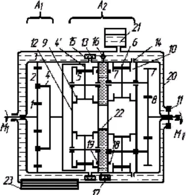
– the given transmission ratio.The differential hydra-mechanical variator comprises two series-connected differential stages (figure1). The differential stage whose input shaft is coupled with the engine and functions as the variator input shaft appears to be like automatic differential gear train with different values of the transmission ratio.
The second differential stage presents hydra-mechanical differential converter possessing two planetary sets one of which is formed of multiple-gear hydropump kinematic links consisting of crown wheel to be connected by inside gearing with satellites; and the other - of kinematic links inside multiple-gear hydraulic actuator with double-row satellites whose inside gearing to be connected with the crown wheel and the external gearing - with central sun gear. The crown wheel of the first planetary set serves in the capacity of hydropump input shaft whose hand of rotation coincides with the direction of variator input shaft rotation and central sun gear of the second planetary set acts as the output shaft of the hydraulic actuator. The axles of both satellites at the first differential stage and hydra-mechanical differential converter are installed in the common body. The body is installed on bearings in the variator case and serves as the common gear carrier comprising a freewheel clutch. Apart from mechanical linkage stipulated by the availability of the mutual gear carrier between the planetary sets of the hydra-mechanical differential converter a dynamic hydraulical connection exists and its loop comprises automatic overload relief valve and adjustable valve2, 3.
actuator. These variations take place in the consequence of variations in relative speed of differential stages’ links at the change of output shaft speed in relation to input shaft permanent speed.
Body 12 of high-torque differential hydra-mechanical gear train is rested on bearings installed in case 20 filled with oil. To compensate oil temperature expansion the case has an expansion tank 21. The first differential stage of the variator presents a mechanical differential gear train comprised of input shaft 1, satellites 2, output member 3 and the gear carrier 4. The second differential stage is a fluid-mechanical differential converter having two planetary sets one of which is formed of multiple-gear hydropump 9 kinematic links consisting of crown wheel 4’ to be connected
by inside gearing with satellites 5; and the other – of kinematic links inside multiple-gear hydraulic actuator 10 with double-row satellites 7-7’whose inside gearing 7 to be connected with the crown wheel 6 and the external gearing 7’ - with central sun gear 8. Both hydropump and hydraulic actuator have intake ports: 15 and 17, and exhaust ports: 14 and 18 – their number is equal to the number of hydropump and hydraulic actuator satellites.
Self-actuated overload relief valve 16 and controlled valve 17 are installed into hydraulic annular channel 22. Freewheel clutch 11 is installed between cage (gear carrier) 12 and case 20, filter 13 is fixed on hydropump intake ports and heat exchanger 23 is mounted in the bottom of case 20. Study of hydromechanical differential variator
Torque Ì1 from the external energy source at non-rotatable gear carrier 12 is conveyed to input link 1 of differential gear train À1 which rotates with the rate n1 and through satellites 2 is conveyed to the gear carrier of the differential device 4 in kinematic link 4-4’. In doing this link 4-4’ rotates in the same direction as input link 1. Rotation of link 4-4’ and satellites 5 creates the working fluid flow which is determined by the parameters of the following equation:
2
' 4 4
ГН н ГН
V p M
M ...(2)
where
M
44'
M
ГН – torque on the hydropump input shaft, Nwm, ðh – fluid pressure, MPa; VÃÍ – hydropump displacement, m3.The theory of work processes in gear hydraulic units states that they produce torque biasing4, 5.
The ratio of resisting moments on drive pinion and gear wheel is equal to
). cos 12
)] 90
cos(
cos 3 12 /( ) cos 12
) 90 cos( cos
3 12 (
2 2 12 1 2
2 1
w w
w w
w w
Н
i z z
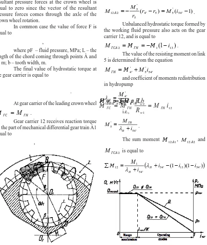
...(3) The distinguishing feature of gear hydraulic units with inside gearing lies in the availability of hydrostatic moment at the gear carrier. Fig. 2 presents projected areas of toothed rings being pressurized by the fluid flow; they come A1 - mechanical differential mechanism; A2 -
hydro-mechanical differential ñonverter; 1 – input element of the differential mechanism, it is also the input shaft of the variator; 2 – satellites; 3 – crown wheel differential mechanism A1; 4 – gear carrier differential mechanism A1, the same input link hydro-mechanical differential converter; 4’ – leading crown wheel hydraulic pump; 5 – satellites of the hydraulic pump; 6 – the crown wheel of the motor; 7-7’ – double-row satellite; 8 – central solar gear shaft; 9 – water pump; 10 – hydraulic motor; 11 – freewheel; 12 – led (chassis) of the variator; 13 – filter; 14 and 19 – respectively, the outlet ports of the hydraulic motor and the hydraulic pump; 15 and 18 – respectively of the inlet window of the motor and the hydraulic pump; 16 – automatic bypass valve; 17 – operated valve; 20 – case; 21 – expansion tank; 22 – annular channel; 23 is a heat exchanger
down on the site of rectangular form with length L and width b.
The resultant of fluid pressure forces F is directed orthogonally to right line ÀÂ and creates unbalanced hydrostatic torque at the gear carrier 4, 5
FH
М
ГС
,where Í – arm of force F, m.
At the same time the moment of the resultant pressure forces at the crown wheel is equal to zero since the vector of the resultant pressure forces comes through the axle of the crown wheel rotation.
In common case the value of force F is equal to
Lb
p
S
р
F
н
н,
where pF – fluid pressure, MPa; L – the length of the chord coming through points À and Â, m; b – tooth width, m.
The final value of hydrostatic torque at the gear carrier is equal to
12 1
2
M
i
R
R
M
М
ГНw w ГН
ГС
.
At gear carrier of the leading crown wheel
ГН
ГС
M
М
.Gear carrier 12 receives reaction torque on the part of mechanical differential gear train À1 equal to
13 1 1
12
M
i
М
А
,
and directed to the side opposite to the direction of input link 1 rotation.
At applying geared pump with inside gearing and two or more driven wheels the torque led to gearwheel 4’ (hydropump torque) is received by the resisting moments acting on hydropump gearwheels 4’ and 5. Upon that the resisting moment on link 5 determines the value of reaction torque at the gear carrier 12 that is equal to
)
1
(
)
(
54'' 5 5 ' 4 5
' 5 2
12
r
r
M
i
r
M
M
А .Unbalanced hydrostatic torque formed by the working fluid pressure also acts on the gear carrier 12, and is equal to
)
1
(
13 12
М
М
i
M
ГСА
ГН
.The value of the resisting moment on link 5 is determined from the equation
' 54 ' 5 '
' 4
M
i
М
M
ГН
and coefficient of moments redistribution in hydropump
' 5 ' ' 4
M
M
Н
.i.e.,
' 54 '
5
i M M
Н ГН
.The sum moment
М
12А1,M
12А2 and2 ГСА
M
is equal to
54' (1 13)(1 54')
'54 1
12 i i i
i M
М Н
Н
Fig. 2. The scheme for determining the hydrostatic torque on the driver
and has the direction coinciding with the direction of input link 1 rotation. This moment is a moment of support and determines maximal coefficient of transformation on the assumption that gear carrier is balanced when sum reaction moment acts on it from hydropump.
The flow of the working fluid through hydropump output ports 19 gets into annular channel 22 and through input ports of hydraulic actuator 18 comes into its working chambers formed by caves of gearwheels 6 and 7. The torque on output shaft of hydraulic actuator is equal to
, ) 1 ( 2 8 ' 7 ' 7 7 13 1 i М М i i М i M V p M II г г ГН ГМ Н ГМ
where ðÍ – fluid pressure, MPa; VGM – hydraulic actuator displacement, m3;
ГН ГМ ГН ГМ г V V M M
i – hydraulic gear transmission
ratio; М77' – torque on hydraulic actuator output
shaft, Nwm,
М
II – torque on variator outputshaft, Nwm,
i
7'8 – gear transmission ratio of inside gearing between gearwheels 7’ and 8.At availability of resistance on hydraulic actuator output shaft the gear carrier receives reaction torques directed to the side opposite to the direction of input shaft rotation. When the working fluid being fed to the geared hydraulic actuator’s working chambers with inside gearing and two or more satellites, as well as in hydropump, the resisting moments on gearwheels 6 and 7 take place. When this takes place, resisting moment on link 6 determines the value of reaction torque from hydraulic actuator on gear carrier 12 which is equal to
)
1
(
)
(
6 7 6' 67 6' 6 1
12
r
r
M
i
r
M
M
ГМ .When further conveying the torque from toothed ring 7’ to the central sun gear 8 reaction torque takes place equal to
)
1
(
7'82
12
M
i
M
ГМ
ГМ
.Just like in hydropump, unbalanced hydrostatic torque formed by the working fluid flow pressure and directed to the side opposite to the direction of input shaft rotation acts in hydraulic actuator with inside gearing. This torque is equal to
76 ' 7 7
2
М
i
М
ГС
.In the consequence of this torque’s action the sum reaction moment on the side of the hydraulic actuator on gear carrier 12 is diminished by this value and is equal to
. 1 1 76 8 ' 7 67 67 13 1 2 2 12 1 12 12 i i i i i i М M M M M М г ГС ГМ ГМ ГМ
Gear transmission ratios of the variator kinematic links are determined on the assumption of gear carrier 12’s balance at the preset transformation coefficient
ГМ
M
М
12
12
or.
1
1
)
1
)(
1
(
76 8 ' 7 67 67 13 ' 54 ' 54 13 ' 54
i
i
i
i
i
i
i
i
i
i
М г Н Н
Gear carrier 12 being common for two differential stages at the availability of the resisting moment on output shaft 8
II
С
M
М
,
is balanced and its rotating speed n12 = 0, and the rotating speed of the variator output shaft
К
n
n
III
,where Ê – transformation coefficient.
At
М
С
M
II the difference in torques on gear carrier 12 is received by freewheel clutch 11. When the rotating speed of the output shaft being diminished under influence of the loadthe pressure in the annular chamber increases up to the pressure of automatic relief valve 16’s actuation, the difference in fluid consumption by hydropump and hydraulic actuator flows from annular channel 22 to inner chamber of body 20. In view of considerable rise of the working fluid temperature at its overflowing through slots in valve 16, such working mode is allowed only for a short period of time in particular, merely at starting a motor vehicle5, 6.
When the load on output shaft II being diminished the reaction torque on gear carrier 12 on the side of hydraulic actuator is also decreased and the flow of hydraulic power being lessened while the mechanical sum moment ÓÌ12 forming at work of differential stages À1 and À2 and input shaft 1’s constant rotating speed, realizes power transmission according to parallel mechanical flow of power. The difference between the sum moment and the reaction torque brings to gear carrier 12’s rotation in the same direction as input I and output II shafts and shaft II’s rotating speed is increased
from
К
n
n
II
I up to nII nI, what determinesthe range of the variator’s automatic regulation
ivar = 1iзад÷1. When doing so, power flows
transfer according to hydraulic and mechanical
loops and at nII nI all the power is transferred by the mechanical control loop7.
When output shaft rotating speed is equal
to
n
II
n
I all links’ speed coefficient are equal to zero, consequently, Q = 0. At changing the speed nII the gear carrier 12’s speed is also being changed and, accordingly, the speeds of hydropump and hydraulic actuator in relation to gear carrier 12. The change of the output shaft rotating speed within the range of nII = 1 / izad up to nII = 0 occurs at n12 = 0. When n12 = 0 the working fluid consumptionГМ
II
ГН
n
V
V
n
Q
4'
and the pressure p = pmax. In connection with power flow transfer at changing the output shaft rotating speed, the parameters of hydraulic power flow and Q are varied according to the plot (figure 3).
In order to provide constant pressure
ðmax within the range of acceleration condition
when
Q
ГН
Q
ГМ , automatic pressure relief valve 16 is involved in hydraulic system and controlled valve 17 is provided therein whose purpose being interruption of the working fluid in the hydraulic loop what is necessary for engine ignition, automobile starting and disconnecting the engine from transmission in the process of motion.CONCLUSION
Comparing to a prototype, infinitely variable adjustment of kinematic and power parameters is implemented at a total absence of any steering system thus reaching the simplicity of design.
The efficiency amelioration happens due to the diminishment of hydrostatic losses in view of the local resisting moments’ lack in the bodies of control, low values of the flow length and speed of the working fluid therein.
Invertibility property of rotor hydraulic machines at the load action on the side of the output shaft provides the possibility of braking with motor. Hydraulic loop damping capabilities stipulate noiselessness, travelling comfort and rim pull consistency on the leading wheels.
The freewheel clutch installed on the gear carrier shaft and automatic pressure relief valve in the hydraulic loop protects the engine within the range of acceleration and «overloading stop» mode.
The comparative economic analysis of product profiling of self-actuated gear boxes, beveled chain variators and toroid progressive transmissions produced by the modern automobile industry of different countries shows the high degree of design-engineering consistency of operations in relation to the existing level of geared transmissions and hydraulic machines manufacture, high extent of universalization, considerably less cost of materials and labor effort and, accordingly, lower cost of production.
optimal power use and, correspondingly, to the considerable diminishment of fuel consumption.
The attainable technical results provide for multifunctional use of the given invention in all fields of machine building.
REFERENCES
1. Mavleev, I.R. Development of efficient schemes and designs high-torque hydromechanical CVTs for vehicles: Author. dis. Cand. tehn. Sciences. -Naberezhnye Chelny, (2007). - 19 p.
2. Voloshko, V.V., Mavleev, I.R. Patent ¹2298125 RF IPC F16H47/04. Differential hydromechanical CVT / “Bull. of inventions” -2007.- ¹12.
3. Voloshko, V.V., Mavleev, I.R. Patent ¹2347966 RF IPC F16H47/04. High-torque differential hydromechanical CVT / “Bull. of inventions”
-2009.- ¹6.
4. Voloshko, V.V., Salakhov, I.I. Patent ¹2384773 RF IPC F16H 3/44. Automatic speed planetary gearbox / “Bull. of inventions” - 2010.- ¹8. 5. Salakhov, I.I. The development of automatic
transmissions rational schemes, based on the planetary system of universal multi-threaded differential mechanism: Author. diss. Candidate of tehn. Science. - Izhevsk : M.T. Kalashnikov IzhSTU, (2013). – p. 24
6. Sharipov, V.M. Building and calculation of tractors / - M.: Publishing Mechanical Engineering, (2004). – 590 p.