IJSRSET173830 | Received : 01 Nov 2017 | Accepted : 20 Nov 2017 | November-December-2017 [(3)8: 210-214]
© 2017 IJSRSET | Volume 3 | Issue 8 | Print ISSN: 2395-1990 | Online ISSN : 2394-4099 Themed Section: Engineering and Technology
210
Performance Enhancement of Vapour Compression Refrigeration System
with Utilization of Condenser Waste Heat in Water Heater
Neeraj Kumar Ram
1, Neelesh Soni
21
Research Scholar, ME Department, ITM University, Gwalior, India
2Assistant Professor, ME Department, ITM University, Gwalior, India
ABSTRACT
Nowadays research work in science & technology has more concern for efficient and economical use of
energy and its effect on our environment system. In the context of dissertation as performance
enhancement of vapour compression refrigeration system with utilization of condenser waste heat in water
heater have been performed by experimental setup which was mounted on wooden support. The entire
instruments are coupled in such a way so that proper observation can be taken simultaneously and all the
parameters can be calculated on the basis of observations taken out during the experiment. The particular
experimental setup having five major components as compressor (R 134a, 100 watt), water and air cooled
condenser, expansion device (capillary tube) and evaporator (Water cooler). Thermocouple and pressure
gauge have incorporated to the setup for measuring the temperature and pressure at different section. In
this experiment, observations have been taken for three cases, without water filled in hot chamber, static
water (4.2 liter) filled in hot chamber and water circulation in hot chamber with velocity 2.12 m /s. After
taking the observations and calculating the results for all three cases it have been concluded that condenser
out temperature found minimum in case II which is 14.2% less from case I and 0 .295% less from case III,
Compressor work found minimum in case II which is 19.54% less from case I and 24.7% less from case
III, COP of the system found maximum in case II which is 26.78% more from case I and 33% more from
case III and refrigerating effect found maximum in case II which is 6.06% more from case I and 1.78%
more from case III. Temperature of water in hot chamber was found maximum 44 ◦c and utilized 254.016
KJ of heat energy.
Keywords :
Coefficient of performance (COP), Condenser Heat, Compressor Work
I.
INTRODUCTION
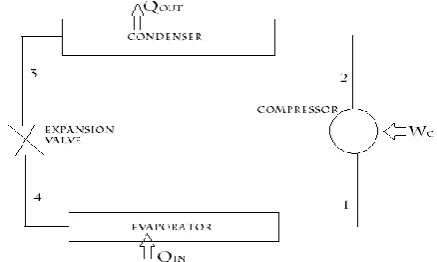
The actual vapour compression cycle is based on Evans-Perkins cycle, which is also called as reverse Rankine cycle. It consist of mainly four components namely compressor, condenser (heat exchanger), expansion device and evaporator as depicted in fig. bellow.
In a vapour compression refrigeration system, refrigeration is obtained as the refrigerant evaporates at low temperatures, in this cycle there are four processes, process 1-2 is compression in which low pressure and temperature working fluid (refrigerant) compressed isentropically to high temperature and pressure, process
Figure 1. Vapour Compression Refrigeration Cycle
exchanger at constant pressure ), process 3-4 isenthalpic expansion ( refrigerant pressure decrease drastically due to throttling) and process 4-1 evaporation( refrigerant takes latent heat of vaporization to sink bodies).The Vapor compression refrigeration system is now-a-days used for all purpose refrigeration. It is usually used for all industrial purposes from a small domestic refrigerator to a big air-conditioning plant. Vapour compression refrigeration systems are the most commonly used among all refrigeration systems. [1]
II.
LITERATURE REVIEW
Prati Kumbhar et.al [4] presented experimental study on waste heat recovery from domestic refrigerator .In this paper they placed water cooled heat exchanger instead of condenser exposed to open atmosphere in vapour refrigeration system. After experiment they found that the System Performance Improved and Hot water Output. Sreejith K et al. [5] presented their experiment in which designed, fabricated and experimentally analyzed a waste heat recovery system for domestic refrigerator. They analyzed the system in three conditions without load, 40W load and 100W load, and also carried out the techno-economic analysis by simply comparing the waste heat recovery system with conventional geger. From experimental result data they found that the waste heat recovery system performs well along with the household refrigerator. Hot water of moderate temperature had been obtained from it. Mula Reddy Ramana Venkata and Harish H.V [6] performed experiment to advance the Coefficient of Performance (COP) by decreasing the Compressor Work and increasing the Refrigerating Effect. Experiment had been carried out on vapour compression refrigeration (VCR) system with R134A (Tetra Fluro Ethane) as working fluid (refrigerant) and their results were recorded. After the introduction of diffuser they found the comparative results, work input to compressor reduced and coefficient of performance increased by around 31%. Sahni Rounak [7] proposed an ejector expansion refrigeration cycle to reduce the expansion losses in vapour compression cycle. The performance of the ejector expansion cycle had been investigated over basic refrigeration cycle and it found that COP were 16% more comparatively over the basic cycle. Singh Monika and Somvanshi Prashant [8] presented their study on different type refrigerant used in refrigeration cycle by using software REFPROP, in which they focused on eco friendly refrigerants and performance of
cycle. Based on software data they found that R410a and R407c were the good replacements for R22 refrigerant, COP values of both the refrigerant were comparable to R22. Upadhyay Neeraj [9] presented the concept of effect of Sub-cooling and Diffuser on the Coefficient of Performance of Vapour Compression Refrigeration System primarily carried out to advance the coefficient of performance of system. Vedil S.N et al. [10] presented theoretical approach to recover the waste heat liberated from vapour compression cycle, which was used to run vapour absorption cycle. The required heat had been given by solar energy and condenser of vapour compression cycle to run the vapour absorption cycle (lower cycle). Reddy Harshavardhan et al. [11] performed experiment to enhance the efficiency of reciprocating compressor AWZ5528EXN. After applying design modifications reductions in losses found approximately 6.88% and the EER of the compressor was found to improve to 3.165. Yadav Prasad G.Maruthi et al. [12] performed experiment to investigate the performance of vapour compression refrigeration of a domestic refrigerator of capacity160 liters by using R-134a and R-404a as working fluid refrigerant.
III.
EXPRERIMENTALSETUP
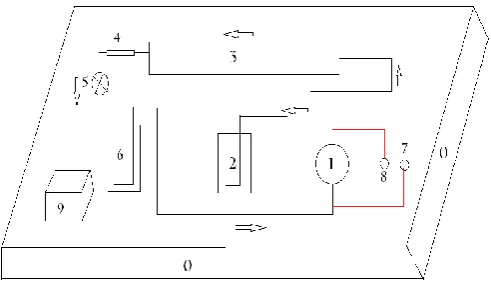
In this experimental setup all components have been mounted on wooden support. The entire instruments are coupled in such a way so that proper observation can be taken simultaneously and all the parameters can be calculated on the basis of observations taken out during the experiment. Simple layout of whole experimental setup is shown in the diagram according to their application .number are depicted in this diagram represents the components which are listed in the table.
List of components according to layout and their specifications.
0. wooden support [Length .63m, Width .40m, Thickness .019m]
6. Cold chamber
(evaporator) [4.2 liter ,tube material Cu, length 4.85 m, diameter 6.5mm]
1. Compressor [100 watt,42L, R134a]
7. Pressuregauge ( suction pressure of compressor)
2. Hot chamber [4.2 liter ,tube material Cu, length 1.2m, diameter 6.5mm ]
8. Pressure
gauge( discharge pressure of compressor)
3. Condenser ( heat exchanger) [ material Cu, length 9.144m, outer diameter 5mm ]
9. Digital thermocouple ( 8 channel temperature measurement)
4. Filter (dryer) 10. Refrigerant (working
fluid)[ R134a ,mass 100gm]
5. Expansion device (capillary tube) [ material Cu, length 2.4m,
diameter 5mm]
IV.
METHODOLOGY
In the context of experimentation of the project all observation has been taken during experiment at RAC lab, ITM UNIVERSITY GWALIOR. In this experiment, observations have been taken for three cases, case I- without water of hot chamber, case-II with water of hot chamber and case-III water circulation in hot chamber. For the circulation of water in hot chamber a window cooler pump was taken which mass flow rate .166 liter per second and velocity 2.12 m/s.
In this experiment various parameters such as compressor in temperature, compressor out temperature, condenser out temperature, evaporator in temperature cold chamber temperature, hot chamber temperature suction pressure and discharge pressure have been measured for three different cases with a fixed time interval of 10 minutes by the help of thermocouple and pressure gauges.
BASIC EQUATIONS [3]
1.Compressor work (WC ) = mr (h2 - h1)---[ i]
Enthalpy relation for super heated horn is given by h2 = h’2 + cp (TSup. – TSat)
2. Condenser heat ( QC) = mr (h2 – h3)---[ii]
Where mr is mass flow rate of refrigerant
3. Evaporator heat (Qe) =mr (h1 – h4)---[iii]
4. COP =
desired effect/work input = (h1 – h4)/ (h2 - h1)
5. Carnot COP = Te /(Tc-Te) ---[iv]
V.
RESULTS AND DISCUSSION
On the basis of experimental observation
parameters and calculation following results have
been obtained and their comparative representation
shown below.
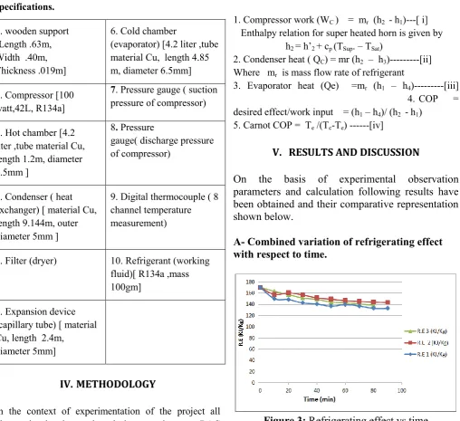
A- Combined variation of refrigerating effect
with respect to time.
Figure 3:
Refrigerating effect vs time
B - Combined variation of COP with respect to
time.
C - Combined variation of Compressor work
with respect to time
Figure 5 :
Compressor work vs time
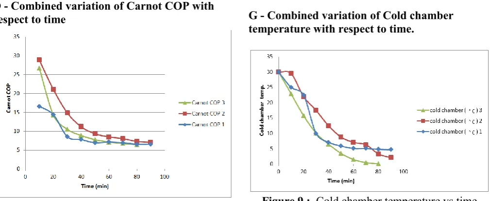
D - Combined variation of Carnot COP with
respect to time
Figure 6 :
Carnot COP vs time
E - Combined variation of Compressor out
temperature with respect to time.
Figure 7 :
Compressor out temperature vs time
F - Combined variation of Condenser out
temperature with respect to time.
Figure 8 :
Condenser out temperature vs time
G - Combined variation of Cold chamber
temperature with respect to time.
Figure 9 :
Cold chamber temperature vs time
H - Combined variation of hot chamber
temperature with respect to time
VI.
CONCLUSION
After conducting the experiments, the following
conclusions are drawn.
a)
Minimum condenser out temperature found in
case II which is 14.2% less from case I and 0
.295% less from case III.
b)
Minimum compressor work found in case II
which is 19.54% less from case I and 24.7%
less from case III.
c)
Maximum COP of the system found in case II
which is 26.78% more from case I and 33%
more from case III.
d)
Maximum refrigerating effect found maximum
in case II which is 6.06% more from case I and
1.78% more from case III.
e)
Temperature of water in hot chamber was
found maximum 44 ◦c and utilized 254.016 KJ
of heat energy.
VII.
FUTURE SCOPE
Experiment may also be conducted by using the hot
water circulation by discharging of it. Surface area
of water cooled condenser may also be increased
by increasing the number of tube coil turn.
Performance optimization may be determined by
using different refrigerant other than R134a.
Incorporation of fins extended surface may be done
for optimization of condenser heat.
VIII.
REFERENCES
[1]. Prasad Manohar, Refrigeration and air
conditioning, New Age International (P) Limited Publishers, 2015, pp. 113-122.
[2]. Arora C.P., Refrigeration and air conditioning, McGraw Hill education India private limited, 2014, pp. 91-93
[3]. Nag P.K., engineering thermodynamics, McGraw Hill Education India private limited, 2013, pp.617-19.
[4]. Prati Kumbhar, Banti Deokate, Akash Bridve, N.D Gadhave and Jivraj Deokate (2017) .Design and Development Waste Heat Recovery from Domestic Refrigerator, International Journal of
Advance Research, Ideas and Innovations in Technology Volume 3, Issue 2, page 912-917. [5]. Sreejith K, T.R. Sreesastha Ram, Mossas V.J,
Nidhin M.J, Nithil E.S, Sushmitha S. (2016) .Experimental Investigation of Waste Heat Recovery System for Household Refrigerator, Research Inventy: International Journal of Engineering and Science Volume 6, Issue 4 page 19-23.
[6]. Dr Venkata Ramana Reddy Mula and H.V.Harish
(2015). Enhancement of Coefficient of
Performance in Vapour Compression Refrigeration Cycle, International Journal of Research in
Aeronautical and Mechanical Engineering,
Volume 3, Issue 10, page 49-62.
[7]. Rounak Sahni (2015). Ejector Expansion
Refrigeration Systems, Research Inventy
International Journal of Engineering and Science Volume 5, Issue 2, page25-29.
[8]. Monika Singh and Prashant Somvanshi (Feb. 2014). Thermodynamic Analysis of Vapour
Compression Refrigeration System using
Alternative Refrigerants, IOSR Journal of Mechanical and Civil Engineering Volume 11, Issue1, page 81-89.
[9]. Neeraj Upadhyay (2014). To study the effect of Sub-cooling and Diffuser on the Coefficient of Performance of Vapour Compression Refrigeration System, International Journal of Research in
Aeronautical and Mechanical Engineering,
Volume 2, Issue 6, page 40-44.
[10].S. N. Vedil, A. Kumar and D. Mahto (2014). Waste heat Utilization of vapour compression cycle, International Journal of Scientific and Research Publications, Volume 4, Issue 11, November 2014 Volume 4, Issue 11, Page 1-4. [11].K.Harshavardhan Reddy, M. Rama Narasimha
Reddy, A.Venkataswami and Dr M.Yohan (2013). Improvement of Energy Efficiency Ratio of Refrigerant Compressor, International Journal of Scientific and Technology Research Volume 2, Issue 5, Page 34 -40..