Journal of Engineering Sciences, Volume 6, Issue 1 (2019), pp. E 1–E 9 E 1 JOURNAL OF ENGINEERING SCIENCES
ЖУРНАЛ ІНЖЕНЕРНИХ НАУК
ЖУРНАЛ ИНЖЕНЕРНЫХ НАУК
Web site: http://jes.sumdu.edu.ua DOI: 10.21272/jes.2019.6(1).e1 Volume 6, Issue 1 (2019)
UDC 66.045.122
Numerical Investigation of the Concave-Cut Baffles Effect
in Shell-and-Tube Heat Exchanger
Petinrin M. O.*, Dare A. A.
University of Ibadan, Oduduwa Rd, 200284 Ibadan, Oyo State, Nigeria
Article info: Paper received:
The final version of the paper received: Paper accepted online:
August 5, 2018 December 24, 2018 December 29, 2018
*
Corresponding Author’s Address:
layopet01@yahoo.com
Abstract. In this paper, the performance of shell-and-tube heat exchangers with single-segmental baffle and vary-ing configurations of concave-cut baffles (10, 15 and 20 %) was investigated. The study was carried out for a heat exchanger having either engine oil, water and air as shell-side fluid. For each configuration of the baffles, the results of both the the k-ε and RNG k-ε turbulent models were in very close agreement. The heat exchangers with concave-cut baffles had higher pressure drops and lower performance factors than that of single-segmental baffle at the same range of mass flow rates for all fluid cases. Also, the concave-cut baffle heat exchangers had lower shell-side heat transfer coefficients at the same pressure drop against that of single-segmental baffles. Thus, the use of concave-cut baffles did not exhibit desirable performance in heat exchanger as compared with the segmental baffles.
Keywords: shell-and-tube heat exchanger, pressure drop, weighted performance factor, weighted heat transfer coef-ficient, concave-cut baffle.
1
Introduction
Heat exchanger is a device which transfers thermal en-ergy between fluids at significantly different temperatures [1]. They are widely used for engineering applications in industries, such as in chemical, petroleum, HVAC, auto and aerospace, electronics, power generation and process industries [2, 3]. The most used and widespread type of heat exchangers found in these industries are the tube types. The high level of acceptance of shell-and-tube heat exchanger (STHE) is due to its robustness and versatile materials used in construction, ease of mainte-nance and very wide range of operating conditions [4–7]. The thermal-hydraulic performance of a heat exchang-er has significant effect on enexchang-ergy requirement and effi-ciency of a system. Thus, an optimally balanced thermal-hydraulic design is required but most often attempting to enhance the heat transfer within a heat exchanger raise its pressure drop, which results in increase power demand of fluid handling equipment within the system [2, 3]. Heat transfer enhancement can be achieved through insertion of baffles on the shell-side of STHE [8]. The baffles in-crease the flow turbulence by creating tortuous motion of the fluid for better interaction with the tube surface. Hence, the geometrical shapes and forms of
baffles affect greatly the overall performance of STHEs [9]. The various baffle designs used in heat exchangers are not limited to segmental, helical, trefoil-hole, disc-and-donought, and rod baffles.
E 2 MECHANICAL ENGINEERING: Computational Mechanics three turbulent models to investigate a heat exchanger
with single-segmental baffles considering the baffle spac-ing to shell diameter ratio for two baffle cuts (25 and 36 %). Their results were in good agreement with the Bell-Delaware method; and the 25 % baffle-cut heat ex-changer had better thermal-hydraulic performance.
The conventional single-segmental baffles are com-monly used in heat exchangers for their high heat transfer capability. Although, some other baffle designs have been reportedly proved to have lower shell-side pressure drops as compared with the single-segmental baffle but their overall performance are reduced by their heat transfer rate [14, 15]. The baffle cut and spacing of single-segmental baffles have much effect on the heat exchanger performance. The optimum baffle spacing ratio, which is the baffle spacing to shell inside diameter, recommended is between 0.3 and 0.6, while the baffle cut ranges from 15 to 45 % of the baffle diameter [16, 17]. As shown in Figure 1, the baffle cut creates a segment known as baffle window, which allows the passage of shell-side fluid from one shell zone to another within the heat exchanger. However, Bouhairie [18] reported that the optimum and widely used allowance is the 25 %.
Figure 1 – Schematic representation of flow inside shell-and-tube heat exchanger
Jozaei et al. [19] studied the performance of a heat ex-changer with varying baffle spacings (101.6, 203.2, 304.8, 406.4, 508.0 and 609.6 mm) and shell inside di-ameter of 477.8 mm. It was observed that there was a reduction in the overall heat transfer coefficient and pres-sure drop as the baffle spacing increased. The optimum ratio of the overall heat transfer coefficient to pressure drop was found between baffle spacing of 203.2 and 304.8 mm, which are ranged between 0.43 and 0.64 of shell inside diameter. Prasanna et al. [20] numerically investigated the effect of 25 and 36 % baffle cuts on the performance of heat exchangers with varying number of baffles from 6 to 12. It was reported that the STHE with 25 % baffle cut had higher heat transfer coefficient and pressure drop than STHE with 36 % baffle cut for the range of shell inlet flow rate of 0.5 to 2 kg/s considered.
Even though quite number of studies have been con-ducted on the performance of various baffle designs and cuts in heat exchanger, studies are rare in open references on the effects of modifying the shape of baffle window. Thus in this study, a numerical investigation of thermal-hydraulic performance of STHEs with the 25 % cut sin-gle-segmental baffle (SS_STHE) and three configurations of concave-cut baffle (CaC_STHE) will be carried out for the same area of baffle window.
2
Research Methodology
2.1
Geometrical model
The profile of the concave-cut baffle was generated by fixing a value for either height, h or profile radius, R and determining the other from iteration while maintaining the same segment or window area as the 25 % cut single-segmental baffle (Figure 2). In order to get the concave profile on the baffle, the start out height, h was kept lower than the segment height, H of the single-segmental baffle. Therefore, based on the ratio of h to the baffle diameter, the configurations of the concave-cut baffles and other selected parameters for modelling the shell-and-tube heat exchanger are presented in Table 1.
a b
Figure 2 – The configurations of a single-segmental (a) and concave-cut (b) baffles
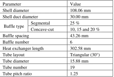
Table 1 – Geometrical parameters of the shell-and-tube heat exchanger
Parameter Value
Shell diameter 108.06 mm Shell duct diameter 30.00 mm
Baffle type Segmental 25 %
Concave-cut 10, 15 and 20 % Baffle spacing 43.26 mm
Baffle number 6
Heat exchanger length 302.58 mm Tube layout Triangular (30°) Tube diameter 15.88 mm
Tube number 19
Tube pitch ratio 1.25
The shell-side working fluids were engine oil, water and air for each run of the heat exchanger while water was kept in the tube. The thermophysical properties of the fluids were as obtained in literature [21, 22].
2.2
The governing equations and numerical
methods
Journal of Engineering Sciences, Volume 6, Issue 1 (2019), pp. E 1–E 9 E 3 Continuity equation:
0 j j u x
(1)
Momentum equations:
2 23 3
j i
j i j
j
i k
T ij ij
j i k
u u p
x x x
u
u u
k
x x x
(2) Energy equation:
p j
T
j j j
T c Tu
x
x
x
(3)
Turbulent kinetic energy:
j
j
T
k
j k j
ku x k P x x
(4)Turbulent dissipation energy:
2
1 2
j T
j j j
k
u
x x x
C P C
k k (5)
where the production term Pk from equations 4 and 5
2 2
3 3
j
i i k
k T ij ij
j j i k
u
u u u
P k
x
x x
x
(6)
The closure constants for the k-ε model are Cε1 = 1.44, Cε2 = 1.92, Cμ = 0.09, σk = 1.0 and σε = 1.3. In the RNG k-ε model the Cε1 is modified as an auxiliary function, which is expressed as
*
1 1 3
1 1
o
C C
(7)
with the following papameter:
2 ij ij
k S S
(8)
Other constants are: C *ε1 = 1.42, Cε2 = 1.68, Cμ = 0.0845, σk = 0.7194, σε = 0.7194, λo = 4.38 and β = 0.012 [26].
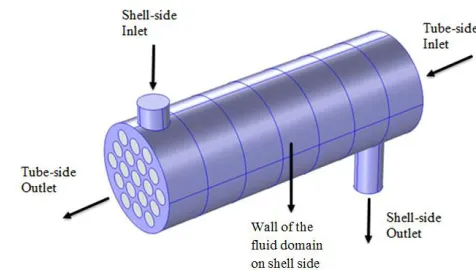
At the inlets of the tubes and shell, velocity-inlet con-ditions were set based on the mass flow rates. The tube-side flow rate was 0.3 kg/s while it was ranged from 0.10 to 3.10 kg/s for engine oil and water, and 0.0025 to 0.0325 kg/s for air on side. The tube- and shell-inlets temperatures were set at 303.15 and 373.15 K re-spectively (Figure 3).
Figure 3 – Boundaries of the computational domain
In order to obtain the relative pressure drops between each inlet and outlet of the shell and tube, zero-gauge pressure was applied at each outlet. Wall functions were specified for walls of the tubes and shell, and baffle sur-faces to account for viscous effects. By assuming a well-insulated heat exchanger, zero heat flux was imposed on the shell outer surface.
Each of the computational domains was discretised in-to unstructured tetrahedral elements and the sets of the governing equations were solved using a finite element based COMSOL Multiphysics CFD code. However, solu-tions to the RNG k-ε model were obtained by replacing the default constants of the k-ε model with the closure constants and auxiliary function of the RNG k-ε model. To improve on the accuracy and stability of the computa-tion, the streamline-upwind Petrov-Galerkin and Galerkin Least-Square were employed [27–29]. Solutions to de-pendent variables were obtained using three segregated solvers: One GMRES solver for velocity and pressure, another one for temperature and one MUMPS solver for turbulent kinetic energy and rate of dissipation [30].
2.3
Heat exchanger performance
The thermal-hydraulic performance of the CaC_STHE was measured against the SS_STHE using two criteria. In the first criterion, the performance was calculated by dividing the shell gain factor of the CaC_STHE against that of SS_STHE at the same Reynolds number or mass flow rate. This factor was defined by Mohammadi et al. [31] as the ratio of the shell-side heat transfer coefficient against the shell-side pressure drop. Thus, the shell gain ratio of a value greater than one would indicate a more suitable concave-cut baffle than single-segmental baffle in heat exchanger and if on the contrary, the single-segmental baffle would be better. Using the second crite-rion, the performance was evaluated by determining the equivalent shell-side heat transfer coefficient of each heat exchanger at the same pressure drop with SS_STHE [8,32]. Thus, the weighted performance of each CaC_STHE against SS_STHE for the same ranges of Reynolds numbers or pressure drops as applied to any of the two criteria was calculated as
1 1 2 N CaC SSN CaC SS
P P
WP
N P P
E 4 MECHANICAL ENGINEERING: Computational Mechanics where P is the performance factor or the equivalent
shell-side heat transfer coefficient for the first or second criterion, respectively. Also the WP is actually the weighted performance factor (WPF) or weighted shell-side heat transfer coefficient (WSHTC) as it is applicable.
3
Results and Discussion
3.1
Model validation
This numerical model was validated by running a sim-ulation of shell-and-tube heat exchanger with horizontal baffles using the experimental data for segmental baffle heat exchanger in [33]. The comparison between the ex-perimental and numerical results for the average Nusselt number and pressure drop in the shell-side are as present-ed in Figures 4 and 5. It can be observpresent-ed that the varia-tions of the numerical results are in good agreement with that of the experiment. The average difference between the experimental and numerical results for Nusselt num-ber and pressure drop are 11 and 26 % respectively. The observed discrepancies may be as a result of the model simplification such as no-leakage flow, and some una-voidable measurement errors.
Figure 4 – Comparison of Nusselt number of the experimental and simulation results
Figure 5 – Comparison of pressure drop of the experimental and simulation results
3.2
Shell-side flow field
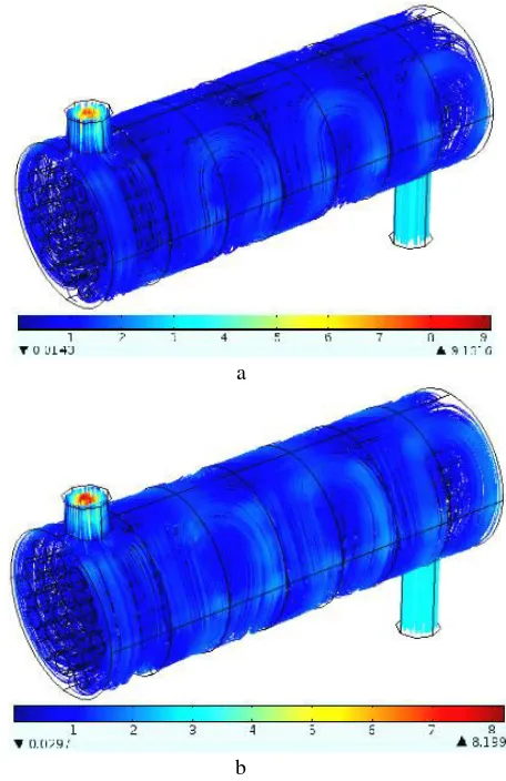
The flow path lines of water at 3.10 kg/s on the shell-sides of the heat exchangers are shown in Fig. 6. It can be observed that the shape of the baffles affects the rambling of the fluid from shell-inlet duct to the outlet duct. The flow in CaC_STHE is more concentrated at the centre of the baffle cut than that of SS_STHE, which spreads over the baffle cut. Also, the fluid velocity is reduced within the shell because of the larger flow area than the shell ducts. The combined fluid mixing by cross- and counter-flows in the shell produces a good interaction of the shell-side fluid with tube outer surfaces which enhances the transfer of heat between the working fluids.
a
b
Figure 6 – Streamline flow of water as shell-side fluid using SS_STHE (a) and CaC_STHE (b)
3.3
Temperature distribution
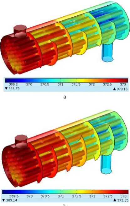
Journal of Engineering Sciences, Volume 6, Issue 1 (2019), pp. E 1–E 9 E 5 a
b
Figure 7 – Temperature distribution in the shell-side (working fluid: engine oil using SS_STHE (a) and CaC_STHE (b)
3.4
Heat transfer coefficient
The plots of the heat transfer coefficient on the shell-side of the SS_STHE and CaC_STHE against the Reyn-olds number are as shown in Fig. 8 for engine oil, water and air respectively. It can be observed for each baffle and working fluid that the heat transfer coefficient in-creases with the Reynolds number, which corresponds to the range of mass flow rates considered for each fluid. Although, the rate of increment in coefficient of heat transfer tends to reduce at higher Reynolds number as indicated for engine oil and water, it increases linearly for air. This can be attributed to the physical nature of each fluid.Amongst other results, the percentage differences in heat transfer coefficients of the SS_STHE with each of the CaC_STHEs are presented in Table 2. From this ta-ble, non-zero positive value indicates higher heat transfer coefficient of CaC_STHE while negative value means
lower heat transfer coefficient of CaC_STHE.Generally, it is observed that CaC_STHEs had lower heat transfer coefficient. This is partly due to the less interaction of the fluids with the outer tubes since the flow is more concen-trated through the centre of the tube bundle. On the con-trary, CaC_STHEs with engine oil gave better heat trans-fer coefficients as depicted from the two turbulent mod-els, and this may also be attributed to fluid’s thermody-namic characteristics.
a
b
c
Figure 8 – Shell-side heat transfer coefficient against the Reynolds number for the engine oil (a), water (b)
E 6 MECHANICAL ENGINEERING: Computational Mechanics
Table 2 – The comprehensive performance of CaC_STHEs
STHE Model Fluid h, % (k-ε)
h, % (RNG
k-ε)
Δp, % (k-ε)
Δp, % (RNG
k-ε)
WPF (k-ε)
WPF (RNG
k-ε)
WSHTC (k-ε)
WSHTC (RNG k-ε)
10 % CaC_STHE
En
g
in
e
o
il
4.40 4.32 –16.91 –16.96 –0.125 –0.127 –0.021 –0.022 15 % CaC_STHE 2.69 2.72 –9.54 –9.59 –0.069 –0.069 –0.010 –0.010 20 % CaC_STHE 0.02 0.03 –8.43 –8.45 –0.084 –0.084 –0.035 –0.034 10 % CaC_STHE
Wate
r –4.14 – –15.76 - –0.199 – –0.090 –
15 % CaC_STHE –7.57 – –7.89 - –0.154 – –0.103 –
20 % CaC_STHE –4.95 – –9.46 - –0.144 – –0.082 –
10 % CaC_STHE
Air
1.30 – –15.29 - –0.140 – –0.056 –
15 % CaC_STHE –0.75 – –7.56 - –0.083 – –0.042 –
20 % CaC_STHE –1.56 – –8.69 - –0.102 – –0.056 –
3.5
Pressure drop
The pressure drops of the SS_STHE and CaC_STHEs for varying Reynolds number are presented in Fig. 9 for the three working fluids. The plots showed that the pres-sure drop increases with increasing Reynolds number (by implication the mass flow rate). However, as the Reyn-olds number (mass flow rate) increases, the pressure drop continues to rise rapidly due to increasing turbulence. The same trend was reported by Kuppan [14], and also ob-served by Wang et al. [32] and Zhang et al. [34] from their studies. The percentage differences in pressure drops for the same range of Reynolds numbers with SS_STHE can as well be found in Table 2. The negative values indicate that the CaC_STHEs have higher pressure drops than the SS_STHE for all the shell-fluids. The higher pressure drops demonstrated by CaC_STHEs could be as a result of the more concentrated cross-flow through the centres of the tube bundles and the subse-quently reduced bypass flow through the shells.
3.6
Performance factor
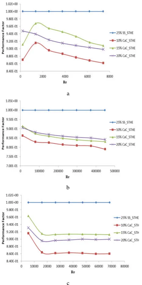
The performance factors of the CaC_STHEs in rela-tion to the SS_STHE at varying Reynolds numbers are as shown in Fig. 10 for all the shell-side working fluids. It is observed that the performance factor of none of the CaC_STHEs is up to a value of one for the range of Reynolds numbers considered. The weighted perfor-mance factors (WPF) of these heat exchangers relative to SS_STHE in the same range of mass flow rates or Reyn-olds numbers are also presented in Table 2. The negative values of the weighted performance factors showed that the CaC_STHEs have lower overall performances in comparison with SS_STHE.
a
b
c
Figure 9 – Pressure drop versus the Reynolds number for the engine oil (a), water (b) and air (c)
Journal of Engineering Sciences, Volume 6, Issue 1 (2019), pp. E 1–E 9 E 7 a
b
c
Figure 10 – The performance factor and the Reynolds Number for the engine oil (a), water (b) and air (c)
as a shell-side working fluid
3.7
Shell side heat transfer and pressure drop
variation
The variations between the shell-side heat transfer co-efficient and pressure drop at the same mass flow rate are as indicated in Fig. 11. It is observed that increase in pressure drop is more rapid than that of heat transfer co-efficient with increasing mass flow rate, and this confirms the assertions given by Kuppan [14] and Mukherjee [16], and conforms with the observations of Wang et al. [8, 32]. Assessing the heat exchangers at the same pressure drop, the SS_STHE exhibits higher heat transfer coeffi-cient than other heat exchangers for all the working flu-ids. The weighted shell-side heat transfer coefficients (WSHTC) of the CaC_STHEs against the SS_STHE are
a
B
c
Figure 11 – Heat transfer coefficient and the pressure drop for the engine oil (a), water (b) and air (c)
as a shell-side working fluid
as depicted as well with other results in Table 2. The negative values are indications that the SS baffles will be more desirable than the CaC baffles based on this criteri-on.
4
Conclusion
E 8 MECHANICAL ENGINEERING: Computational Mechanics
5
Nomenclature
STHE Shell-and-Tube Heat Exchanger; u Velocity component, m/s;
p Pressure, Pa; T Temperature, K; x Cartesian coordinate;
cp Specific heat capacity at constant pressure,
J/(kg·K);
k turbulence kinetic energy, m2/s2; Re Reynolds number;
PrT Turbulent Prandtl number; Δp Pressure drop, Pa;
h Heat transfer coefficient, W/(m2·K); Nu Nusselt number;
P Performance factor;
WPF Weighted performance factor;
WSHTC Weighted shell-side heat transfer coeffi-cient;
ρ Density, kg/m3 ;
μ Dynamic viscosity, Pa·s; μT Turbulent Eddy viscosity, Pa·s;
η Thermal conductivity, W/(m· K);
ηT Turbulent thermal conductivity, W/(m·K);
ε Dissipation rate, m2 /s3; i, j, k Tensor.
References
1. Dubey, V. V. P., Verma, R. R., Verma, P. S., & Srivastava, A. K. (2014). Steady State Thermal Analysis of Shell and Tube Type Heat Exchanger to Demonstrate the Heat Transfer Capabilities of Various Thermal Materials using Ansys. Glob. Journals Inc., Vol. 14, pp. 1–7.
2. Kapale, U. C., & Chand, S. (2006). Modeling for shell-side pressure drop for liquid flow in shell-and-tube heat exchanger. Int. J.
Heat Mass Transf., Vol. 49, pp. 601–610, doi: 10.1016/j.ijheatmasstransfer.2005.08.022.
3. Nasiruddin, M. H. K. (2007). Heat transfer augmentation in a heat exchanger tube using a baffle. Int. J. Heat Fluid Flow, Vol. 28, pp. 318–328, doi: 10.1016/j.ijheatfluidflow.2006.03.020.
4. Petinrin, M. O., & Dare, A. A. (2016). Performance of Shell and Tube Heat Exchangers with Varying Tube Layouts. Br. J. Appl.
Sci. Technol., Vol. 12, pp. 1–8, doi: 10.9734/BJAST/2016/20021.
5. Wang, Q., Zeng, M., Ma, T., Du, X., & Yang, J. (2014). Recent development and application of several high-efficiency surface heat exchangers for energy conversion and utilization. Appl. Energy, doi: 10.1016/j.apenergy.2014.05.004.
6. Zhou, J. F., Wu, S. W., Chen, Y., & Shao, C. L. (2015). Semi-numerical analysis of heat transfer performance of fractal based tube bundle in shell-and-tube heat exchanger. Int. J. Heat Mass Transf., Vol. 84, pp. 282–292, doi: 10.1016/j.ijheatmasstransfer.2015.01.038.
7. Mohammadi, K., & Malayeri, M. R. (2013). Parametric study of gross flow maldistribution in a single-pass shell and tube heat exchanger in turbulent regime. Int. J. Heat Fluid Flow, Vol. 44, pp. 14–27, doi: 10.1016/j.ijheatfluidflow.2013.02.010.
8. Wang, Q., Chen, G., Zeng, M., Chen, Q., Peng, B., Zhang, D., & Luo, L. (2010). Shell-side heat transfer enhancement for shell-and-tube heat exchangers by helical baffles. Chem. Eng. Trans., Vol. 21, pp. 217–222, doi: 10.3303/CET1021037.
9. El Maakoul, A., Laknizi, A., Saadeddine, S., El Metoui, M., Zaite, A., Meziane, M., & Ben Abdellah, A. (2016). Numerical comparison of shell-side performance for shel and tube exchangers with trefoil-hole, helical and segmental baffles. Appl. Therm. Eng., doi: 10.1016/j.applthermaleng.2016.08.067.
10. Zhou, G., Xiao, J., Zhu, L., Wang, J., & Tu, S. (2015). A numerical study on the shell-side turbulent heat transfer enhancement of shell-and-tube heat exchanger with trefoil-hole baffles. Energy Procedia, Vol. 75, pp. 3174–3179, doi: 10.1016/j.egypro.2015.07.656.
11. Wang, Y., Dong, Q., & Liu, M. (2007). Characteristics of Fluid flow and heat transfer in Shellside of Heat Exchangers with Longitudinal Flow of Shellside Fluid with Different Supporting structures. Challenges of Power Engineering and Environment, Springer, pp. 474–475.
12. You, Y., Fan, A., Lai, X., Huang, S., & Liu, W. (2013). Experimental and numerical investigations of shell-side thermo-hydraulic performances for shell-and-tube heat exchanger with trefoil-hole baffles. Appl. Therm. Eng., Vol. 50, pp. 950–956, doi: 10.1016/j.applthermaleng.2012.08.034.
13. Ozden, E., & Tari, I. (2010). Shell side CFD analysis of a small shell-and-tube heat exchanger. Energy Convers. Manag., Vol. 51, pp. 1004–1014, doi: 10.1016/j.enconman.2009.12.003.
14. Kuppan, T. (2013). Heat Exchanger Design. Taylor and Francis, Boca Raton.
15. Shah, R. K., & Sekulic, D. P. (2003). Fundamentals of heat exchanger design. John Wiley and Sons, Hoboken. 16. Mukherjee, R. (1998). Effectively design shell-and-tube heat exchangers. Chem. Eng. Prog.
17. Sinnott, R. K. (2005). Chemical Engineering Design. Coulson & Richardson’s Chemical Engineering, Elsevier, Butterworth-Heinemann, Oxford.
18. Bouhairie, S. (2012). Selecting Baffles for Shell-and-Tube Heat Exchangers. Heat Transf., pp. 27–33.
Journal of Engineering Sciences, Volume 6, Issue 1 (2019), pp. E 1–E 9 E 9
20. Prasanna, V., Purushothama, H. R., et al. (2013). A numerical analysis of hydrodynamic and heat transfer effects of shell-and-tube heat exchanger for different baffle space and cut. Mech. Confab., Vol. 2.
21. Bergman, T. L., Lavine, A. S., Incropera, F. P., & Dewitt, D. P. (2011). Fundamentals of heat and mass transfer. John Wiley and Sons, New Jersey.
22. Cengel, Y. A., & Ghajar, A. J. (2015). Heat and mass transfer: fundamentals and applications. McGraw-Hill, New York. 23. You, Y., Chen, Y., Xie, M., Luo, X., Jiao, L., & Huang, S. (2015). Numerical simulation and performance improvement for a
small size shell-and-tube heat exchanger with trefoil-hole baffles. Appl. Therm. Eng., Vol. 89, pp. 220–228, doi: 10.1016/j.applthermaleng.2015.06.012.
24. Tannehill, J. C., Anderson, D. A., & Pletcher, R. H. (1997). Computational fluid mechanics and heat transfer. Taylor and Fran-cis, Washington.
25. Wilcox, D. C. (2006). Turbulence modeling for CFD. DCW Industries, California.
26. Marzouk, O. A., Huckaby, E. D. (2010). Simulation of a swirling gas-particle flow using different k-epsilon models and particle-parcel relationships. Eng. Lett., Vol. 18.
27. COMSOL (2013). CFD module user’s guide. COMSOL AB.
28. Fries, T., & Matthies, H. G. (2004). A Review of Petrov-Galerkin Stabilization Approaches and an Extension to Meshfree Methods. Inst. Sci. Comput. Tech. Univ. Braunschweig, pp. 1–68.
29. Zienkiewicz, O. C., & Taylor, R. L. (2000). The Finite Element Method: Fluid Dynamics. Butterworth and Heinemann, Oxford. 30. Petinrin, M. O., Dare, A. A., & Asaolu, G. O. (2016). Finite Element Stabilization Methods and Solvers for Heat Exchanger
Ap-plications: A Review. Proc. Int. Conf. Mech. Eng. Energy Technol. Manag., pp. 977–987.
31. Mohammadi, K., Heidemann, W., & Muller-Steinhagen, H. (2009). Numerical Investigation of the Effect of Baffle Orientation on Heat Transfer and Pressure Drop in a Shell and Tube Heat Exchanger With Leakage Flows. Heat Transf. Eng., Vol. 30, pp. 1123–1135, doi: 10.1080/01457630902972694.
32. Wang, Q., Chen, Q., Chen, G., & Zeng, M. (2009). Numerical investigation on combined multiple shell-pass shell-and-tube heat exchanger with continuous helical baffles. International Journal of Heat and Mass Transfer, Vol. 52, pp. 1214–1222, doi: 10.1016/j.ijheatmasstransfer.2008.09.009.
33. Zhang, J., Li, B., Huang, W., Lei, Y., He, Y., & Tao, W. (2009). Experimental performance comparison of shell-side heat trans-fer for shell-and-tube heat exchangers with middle-overlapped helical baffles and segmental baffles. Chemical Engineering Sci-ence, Vol. 64, pp. 1643–1653, doi: 10.1016/j.ces.2008.12.018.
34. Zhang, M., Meng, F., & Geng, Z. (2015). CFD simulation on shell-and-tube heat exchangers with small-angle helical baffles.
Front. Chem. Sci. Eng., pp. 1–11, doi: 10.1007/s11705-015-1510-x.
Числове дослідження ефекту увігнуто
-
вирізаних перегородок у теплообміннику
ПетінрінМ. О., ДареА. А.
Університет м. Ібадан, Обудува роуд, 200284, м. Ібадан, Нігерія
Анотація. У роботі досліджено ефективність теплообмінних апаратів з односегментними перегородками і різними їх конфігураціями увігнуто-вирізаних перегородок (10, 15 і 20 %). Дослідження проводилось для теплообмінника з трьома робочим середовищами: моторне масло, вода, повітря. Для кожної конфігурації перегородок отримані результати, добре узгоджені для двох моделей турбулентності: k-ε і RNG k-ε. Підтверджено, що теплообмінники з увігнутими перегородками мають більші перепади тиску і нижчі показники ефективності, ніж одиничні сегментні перегородки у тому ж массогабаритному діапазоні. Крім того, теплообмінники з увігнуто-вирізаними перегородки мають нижчі коефіцієнти теплопередачі зі сторони оболонки за однакового перепаду тиску порівняно з коефіцієнтом теплопередачі для односегментних перегородок. Таким чином, використання перегородок з увігнутим вирізом не сприяє бажаному підвищенню ефективності теплообмінника порівняно з сегментними перегородками.