Performance of FM-DCSK Communication Systems with
Timing Synchronization Error
Shaoyuan Chen*
The Department of Radio Frequency, China Youke Communication Technology Co., Ltd, Fuzhou, Fujian 350007, China.
* Corresponding author. Tel.: +86-18559185107; email: [email protected] Manuscript submitted September 16, 2014; accepted March 28, 2015.
doi: 10.17706/ijcce.2015.4.4.290-297
Abstract: Performance of frequency-modulated differential chaos shift keying (FM-DCSK) communication
systems with timing synchronization error is investigated over the additive white Gaussian noise (AWGN) and the multipath channels in this paper. A multi-frame FM-DCSK system is proposed, and compared with the conventional one in terms of the effect of synchronization error on the bit error rate (BER) performance. Simulation results show that the proposed system can tolerate more synchronization error than the conventional one.
Key words: Earlier timing, frequency-modulated differential chaos shift keying (FM-DCSK), later timing, multi-frame, synchronization error.
1.
Introduction
Chaotic communication systems employ non-periodic chaotic waveform to convey information [1], [2]. To date, several chaotic modulation schemes have been proposed, such as chaos shift keying (CSK), chaos on-off keying (COOK), differential chaos shift keying (DCSK) [3] and frequency-modulated differential chaos shift keying (FM-DCSK) [4], etc. Chaotic modulation is a promising technique, since chaotic waveform has an inherent wideband property. This property enables the chaos-based systems to resist frequency-selected fading in multipath environments and makes the power spectrum density of the systems fairly low, preventing the systems from intercepting.
Coherent detection can be used for chaotic schemes if the basis function can be recovered precisely in the receiver. However, precise recovering cannot be achieved if the signal propagation environment is poor. Alternatively, non-coherent detection is commonly employed in chaotic schemes, such as COOK, DCSK and FM-DCSK, to name just a few. Among them, FM-DCSK is proven not only having the best noise performance but also possessing a superior capability of anti-interference over multipath fading channels without the need of some compensatory measures such as channel estimation, equalization, or Rake reception [5]-[7].
DCSK systems and enhanced DCSK systems over the additive white Gaussian noise (AWGN) channel are reported in [10], and in [11], [12], the performance of the FM-DCSK UWB systems with timing error is investigated under the IEEE 802.15.4a channels.
This paper analyzes and simulates the effects of the timing synchronization errors on the FM-DCSK communication systems over both the AWGN and multipath channels. An FM-DCSK system with multi-frame structure is proposed. Simulations show that the proposed system not only has better bit error rate (BER) performance but also offers better robustness to timing error, as compared to the conventional one with the same data rate.
The rest of the paper is organized as follows. Section 2 illustrates the system model with synchronization error. A multi-frame FM-DCSK system is proposed in Section 3, and simulation results are presented in Section 4. Finally, conclusion is drawn in Section 5.
2.
System Model with Synchronization Error
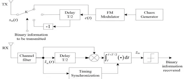
The block diagram of the FM-DCSK system is shown in Fig. 1, where s tm( ) denotes the transmitted
signal, s tɶm( ) denotes the received useful signal through the channel filter, and zm is the observation signal.
Fig. 1. Block diagrams of the FM-DCSK transmitter (TX) and receiver (RX).
The binary FM-DCSK modulation unit transmits a reference segment of the chaotic signal and its repeated or reverse segment, according to the digital information “1” or “0”. The modulated signal for transmission is represented by two orthogonal basic functions, g t1( ) and g t2( ), as follows:
1 1 2 2
( ) ( ) ( ),
m m m
s t =s g t +s g t (1)
11 12
21 22
( ) ( 0),
( ) (0 ),
b
b
s s E
s s E
=
= (2)
where sm(t) is the modulated signal for transmission and Eb is the bit energy. m = 1 if the transmitted information is “1” and m = 2 if the transmitted information is “0”. The two basic orthogonal functions are
1
2
( ), 0 2 ( )
( ), ,
2 2
( ), 0 2 ( )
( ), ,
2 2
T
c t t
g t
T T
c t t T
T
c t t
g t
T T
c t t T
+ ≤ <
=
+ − ≤ <
+ ≤ <
=
− − ≤ <
where T is the symbol duration and c(t) is the frequency-modulated chaotic carrier, whose bit energy has been normalized to one.
Let h t1( ) and h t2( ) denote the impulse response of radio propagation channel and channel filter,
respectively, and n(t) is the AWGN with zero-mean and variance N0. In the FM-DCSK receiver, the
observation signal is given by
(
)
[
]
(
)
(
)
ˆ ˆ ˆ ˆ
( ) / 2
( ) ( ) / 2 / 2 .
I
I
T m
T
m m
z r t r t T dt
s t n t s r T nr T dt
τ τ τ τ
+
+
= −
= + +
∫
∫
ɶ ɶ ɶ ɶ(4)
Here, r t( )=s tɶm( )+n tɶ( ).
1 2
( ) ( ) ( ) ( )
m m
s tɶ =s t ⊗h t ⊗h t is the received useful signal through the channel filter,
1 2
( ) ( ) ( ) ( )
n tɶ =n t ⊗h t ⊗h t is the noise signal through the channel filters and ⊗ represents convolutional
operation. Moreover, τˆ represents the actual integral starting point determined by the timing synchronization algorithm as show in Fig. 2, where τ denotes the receiver's ideal integral starting point.
I
T is the integral window length.
(k-1) th bit kth bit (k+1)th bit
r(t-T/2) r(t)
T/2
T
Chaotic waveform
t
t
t=0
Case 1 Case 2 Case 3
Fig. 2. Three cases of timing synchronization results. The three cases indicate different integral starting points, respectively.
As shown in Fig. 2, there are three cases of timing synchronization results, i.e., τ τˆ= − ∆| τ| (Case 1),
ˆ
τ τ= (Case 2), and τ τˆ= + ∆| τ| (Case 3), where ∆ = −τ τ τˆ is the synchronization error. Noise is not
shown in the figure for simplicity. In this paper, the cases of ∆ =τ 0, ∆ >τ 0 and ∆ <τ 0 are called perfect synchronization, later timing and earlier timing, respectively.
3.
Proposed Multi-frame FM-DCSK
In the conventional FM-DCSK system, each symbol contains only one frame, where the first half frame contains the reference signal and the second half frame contains the data signal. In this section, a multi-frame binary FM-DCSK system is proposed. In this new system, the symbol period is as same as that of the conventional system. Each symbol contains Nf frames, and each frame consists of a reference signal and a data signal. To achieve this, there are 2Nf –1 delay modules in the transmitter for the proposed multi-frame systems as illustrated in Fig. 3, where each delay module has T/2Nf delay duration, and {I1, …,
f
N
I } = {1,…,1} when the transmitted data is “1” or { I1,…, f
N
(
)
(
)
(
)
(
)
1
( ), 0
, 2
2 , 2 3
( )
2 1 , (2 1) ,
D
D D D
D D D
f D f D
c t t T
c t T T t T
c t T T t T
g t
c t N T N T t T
+ ≤ <
+ − ≤ <
+ − ≤ <
=
+ − − − ≤ <
⋮
(
)
(
)
(
)
(
)
2( ), 0
, 2
2 , 2 3
( )
2 1 , (2 1) ,
D
D D D
D D D
f D f D
c t t T
c t T T t T
c t T T t T
g t
c t N T N T t T
+ ≤ <
− − ≤ <
+ − ≤ <
=
− − − − ≤ <
⋮
where TD= T/2Nf.
The receiver of the proposed multi-frame system is similar to that of conventional one except that the delay module has the delay duration of T/2Nf. The performance of the proposed system with timing synchronization inaccuracy will be investigated in the next section.
4.
Simulation Results
In the simulations, the chaotic map for generating chaos is the Logistic map [1]. The other system parameters are set as follows: symbol period T = 1 µ R = 1 Mbps) and 2 µ R
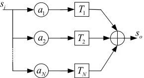
respectively; sample frequency fs = 64 MHz. The simulation channels are the AWGN channel and multipath channel, respectively. The multipath channel is modeled as a tapped delay line shown in Fig. 4, where N is the number of paths, {a1, a2…, aN} and {T1, T2…, TN} are decay factors and delays of paths, respectively. The
integral window length TI is set as T/2 if not indicated.
Delay
T/2Nf
c(t)
I1
INf
sm(t)
… … Delay T/2Nf Delay T/2Nf Delay T/2Nf I2 …
Fig. 3. A multi-frame structure of the FM-DCSK transmitter.
2 T N T i s o s 1 a 2 a N a 1 T
Fig. 4. Tapped delay line model of a multipath channel.
4.1.
Performance over the AWGN Channel and the Multipath Channel
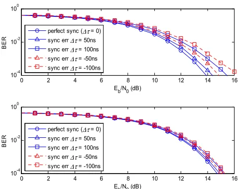
Moreover, the system with T = 1µshas better performance than that with T = 2µsbut the latter is less sensitive to the synchronization error since it has longer symbol duration than the former.
Fig. 5. BER Performance of the systems with perfect synchronization and imperfect synchronization over the AWGN channel: T = 1µs (top); T = 2µs (bottom).
Fig. 6. BER Performance of the systems with perfect synchronization and imperfect synchronization over the multipath channel: T = 1µs (top); T = 2µs (bottom).
Further, the BER performance of the system is simulated over the multipath channel, with decay factors of {a1 = 0.4, a2 = 0.4, a3 = 0.2} and delays of {T1 = 0ns, T2 = 10ns, T3 = 50ns}. Fig. 6 shows the performance of
the FM-DCSK system with perfect synchronization (∆ =τ 0), later timing (∆ >τ 0) and earlier timing (∆ <τ 0), respectively, over the multipath channel. Again, one can observe that the BER performance is
deteriorated by the synchronization error and the system with longer symbol duration (T = 2µs)is more robust to the synchronization error than the system with shorter symbol duration (T = 1µs), which is
similar to the result over the AWGN channel. Meanwhile, it is worth noticing that with the same synchronization error, the later timing outperforms the earlier timing in terms of BER performance over the multipath channel. This phenomenon is caused by the multipath effect, which makes the signal spread in the time domain. Thus, the integral interval of the later timing contains more useful signal energy and less inter-symbol interference (ISI) than that of the earlier timing. The more useful signal energy is captured
0 5 10 15
10-4 10-2 100
E
b/N0 (dB)
B
E
R
perfect sync (∆τ = 0) sync err ∆τ = 50ns sync err ∆τ = 100ns sync err ∆τ = -50ns sync err ∆τ = -100ns
0 5 10 15
10-4 10-2 100
E
b/N0 (dB)
B
E
R
perfect sync (∆τ = 0) sync err ∆τ = 50ns sync err ∆τ = 100ns sync err ∆τ = -50ns sync err ∆τ = -100ns
0 2 4 6 8 10 12 14 16
10-4 10-2 100
Eb/N0 (dB)
B
E
R
perfect sync (∆τ = 0) sync err ∆τ = 50ns sync err ∆τ = 100ns sync err ∆τ = -50ns sync err ∆τ = -100ns
0 2 4 6 8 10 12 14 16
10-4 10-2 100
Eb/N0 (dB)
B
E
R
and less ISI is induced, the better the BER performance is.
4.2.
The Effect of Integral Window Length
From Fig. 2, it is clear that the integral in (4) with TI= T/2 will induce ISI when ∆ ≠τ 0, which deteriorates the performance of the system. Thus, there exists an optimum integral interval length to further improve the BER performance of the system when the timing synchronization is imperfect.
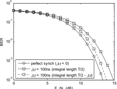
Fig. 7 shows the effect of integral window length on the BER performance of the system with synchronization error Δτ = 100 ns over the AWGN channel. One can observe that the BER performance of the system with the new integral length TI= T/2 – Δτ is improved compared with that with fixed integral length T/2. Therefore, an algorithm estimating the optimum integral length (e.g., [13], [14]) can be further developed to enhance the BER performance of the system in the case of synchronization error, which is out of the scope of this paper.
Fig. 7. Performance comparison between integral window lengths of T/2 and T/2 – Δτ, respectively, in the case of synchronization error Δτ = 100ns (T = 1µs).
Fig. 8. Performance comparison between conventional single-frame FM-DCSK and the proposed
multi-frame FM-DCSK over the AWGN (left) and the multipath (right) channels (T = 1µs, Nf= 4).
4.3.
The Performance of the Proposed Multi-frame System
Finally, the performance of the proposed multi-frame system over both AWGN and multipath channels is
0 5 10 15
10-4 10-3 10-2 10-1 100
Eb/N0 (dB)
B
E
R
perfect synch (∆τ = 0) ∆τ = 100ns (integral length T/2) ∆τ = 100ns (integral length T/2 - ∆τ)
0 50 100
10-5 10-4 10-3 10-2 10-1
synch error (ns)
B
E
R
single-frame 11dB single-frame 13dB multi-frame 11dB multi-frame 13dB
0 50 100
10-4 10-3 10-2 10-1
synch error (ns)
B
E
R
evaluated and shown in Fig. 8. It can be observed that over the AWGN channel, the proposed multi-frame FM-DCSK has better BER performance in both cases of perfect and imperfect timing synchronization, as compared to the conventional FM-DCSK with single frame. And for the multipath channel, one can observe that although the single-frame FM-DCSK offers the similar BER performance to the multi-frame one in the case of perfect synchronization when Eb/N0 =13 dB, the multi-frame FM-DCSK still shows obvious
performance advantage as synchronization error increases. Therefore, it is clear that the proposed new system is more reliable in the case of timing synchronization error over both the AWGN and multipath channels.
5.
Conclusions
In this paper, the performance of the FM-DCSK communication systems with the synchronization error over both the AWGN and the multipath channels has been investigated. A multi-frame FM-DCSK system is proposed, and compared with the conventional one in terms of the effect of synchronization error on the BER performance. Simulation results show that the proposed system has more synchronization error tolerance than the conventional one, which makes it more robust against the imperfect synchronization in the practical applications.
Acknowledgment
The author would like to thank Prof. Lin Wang at Xiamen University, Chair Prof. Guanrong Chen at City University of Hong Kong, and Prof. Jianzhong Zhang at Ocean University of China for their kind supports.
References
[1] Tse, C. K., & Lau, F. C. M. (2003). Chaos-Based Digital Communication Systems. New York: Springer-Verlag.
[2] Kolumbán, G., Kennedy, M. P., & Chua, L. O. (1997). The role of synchronization in digital communications using chaos — Part I: Fundamentals of digital communications. IEEE Trans. Circuits Syst.-I, 44(10), 927-936.
[3] Kolumban, G., Vizvari, B., Schwarz, W., & Abel, G. (1996). Differential chaos shift keying: A robust coding for chaos communication. Proceedings of Int. Workshop Non-linear Dyn. Electron. Syst. (pp. 87–92). Seville, Spain.
[4] Kolumbán, G., Kennedy, M. P., Kis, G., & Jákó, Z. (1998). FM-DCSK: A novel method for chaotic communications. Proceedings of IEEE Int. Symp. on Circuits and Syst. (pp. 477-480).
[5] Ye, L., Chen, G., & Wang, L. (2005). Essence and advantages of FM-DCSK technique versus conventional spread-spectrum communication methods. Circuits, Syst. Signal Process, 24(5), 657–673.
[6] Wang, L., Zhang, C., & Chen, G. (2008). Performance of an SIMO FM-DCSK communication system. IEEE Trans. Circuits Syst. II, Express Briefs, 55(5), 457-461.
[7] Min, X., Xu, W., Wang, L., & Chen, G. (2010). Promising performance of a frequency-modulated differential chaos shift keying ultra-wideband system under indoor environments. IET Commun., 4(2), 125–134.
[8] Kennedy, M. P., Kolumbán, G., Kis G., & Jákó, Z. (2000). Performance evaluation of FM-DCSK modulation in multipath environments. IEEE Trans. Circuits Syst.-I, 47(12), 1702-1711.
[9] Kis, G. (2005). Performance analysis of chaotic communications systems. Ph.D. dissertation, Dept. Measurement and Information Systems, Budapest University of Technology and Economics, Hungary. [10]Kim, Y., Kim, J., Kim, J.-H., & Kang, J. (2006). Comparison of DCSK receiver and enhanced DCSK receiver
Australia.
[11]Chen, S., Xu, W., Wang, L., & Kwak, K. S. (2009). Performance of FM-DCSK UWB with timing error.
Proceedings of Int. Symp. on Communication and Information Technology. Incheon, Korea.
[12]Chen, S., Wang, L., & Chen, G. (2010). Data-aided timing synchronization for FM-DCSK UWB communication system. IEEE Trans. Ind.Electron., 57(5).
[13]Franz S., & Mitra, U. (2004). Integration interval optimization and performance analysis for UWB transmitted reference systems. Proceedings of Joint UWBST and IWUWBS (pp. 26-30). Kyoto, Japan. [14]Zhang R., & Dong, X. (2008). Synchronization and integration region optimization for UWB signals with
non-coherent detection and auto-correlation detection. IEEE Trans. Commun., 56(5), 790–798.
Shaoyuan Chen was born in Fuqing, China, in 1984. He received the B.S. degree in communication engineering in 2007 and the Ph.D. degree in communication and information systems in 2013, both from Xiamen University, Fujian, China.