Intelligent Car Security System Microcontroller based
Ahmed Zuhair, Mansoor Ali
Department of Electrical and Computer Engineering
Caledonian College of Engineering, Oman
Ali Al-Humairi
Department of Communication Technologies, Duisburg-Essen University, Germany
ABSTRACT
Theft attempts and crashing of cars due to careless parking are common issues in unattended public parking lots. This paper presents an intelligent car security system that provides security to the car against theft and crashing in parking lots. The main parts of the system are GSM and GPS modems, Camera, XYZ sensor and Microcontroller. The design focus is to make a highly secure, flexible, reliable and cost effective system. Any crash that happens to the car in the parking lots is immediately communicated to the owner through SMS. Motion sensors detect any vibration such as theft or crash and instantly capture the picture of the incident. The system also saves the picture of any damage caused to the vehicle rendering it as an evidence for further investigation in future. A prototype of the proposed system has been implemented. The test results prove that the system can monitor the parking area of the vehicle, inform the car owner about the status and the location of the car in case of any crash and helps in identifying who is responsible for such an incident by detecting the vibration and taking pictures around the parking area.
Keywords
Microcontroller, Security, GPS, GSM
1.
INTRODUCTION
A car is always a precious possession to its owner either because of its functionality or as a prestige symbol. It is often seen that people do not hesitate to put in their hard earned money to buy the best car that they can afford. It is important that the owner need to do whatever possible using available technologies to protect and safeguard the car. A wide range of gadgets are available in the market as a solution to this problem. However, each one of them has its own merits and demerits either being not able to perform the desired task effectively or in a limited way by failing to cover the whole gambit of security [1].
Careless parking often leads to damage to nearby vehicles and this commonly happens in public parking lots where vehicles are parked for long time un-attended. Theft attempts are also common in such places. Most of the time it is difficult to accurately figure out how such incidents happened and who were at fault. This is a common problem faced by all vehicle users who park their vehicles in public parking lots. The damage caused by such incidents often ranges from simple scratches to severe crashes leading to loss of money and time to the user. Hence it is highly desirable to have an automatic system which gives the full information about the incident which can be used by the vehicle user to identify how it happened and by whom.
This paper presents the design and development of an intelligent and cost effective smart car parking security system which given complete information about theft attempts and crash incidents that happen in parking lots due to careless
parking of vehicles. Effort is made to compare the available security systems based on their design and to come up with a system that excels in performance both at the security level and being cost-effective.
The rest of the paper is organized as follows. Section 2 presents the related work. The Requirements Analysis is defined in section 3. In section 4, System Overview is discussed. The Experimental setup is described in section 5.Section 6 presents the Results and Analysis and we conclude the paper in the final section.
2.
RELATED WORK
A plethora of works have been done on working out technical modalities for car security systems in both states while it is parked and also while on the move [2]. Literature pertaining to car automated parking, car monitoring and car security systems using various techniques and methodologies has been analyzed and compared.
Rashidi, Ariff and Ibrahim [3], has been proposed a car monitoring system using the Bluetooth Security System. The main thrust of the system is on the efficacy of the Bluetooth system to prevent the car from being encroached upon or being involved in a theft. It can be configured and accessed through mobile smart phones using the Bluetooth communication module with an intelligent built-in alarming alert which the car user can turn on or off. The triggering of an alarm would send an intruder alert message to the user’s mobile phone and he would rush to his car and there is a good possibility of the intruder to the car to be caught and the car to be saved from being stolen.
Balajee and Manikandan [4] proposed an automobile security system based on face recognition structure using Global System for Mobile Communications (GSM) [5] network. The authors developed a car security system by using Global Positioning System (GPS) [7] module, a GSM and a tiny face detection webcam and a control module. The web cam is hidden in the steering wheel of the vehicle. The system detects the face in the vehicle during the time when someone is in the car. It also makes an alarm sound if that option is opted for. After detecting the face in the alarm period, one alarm signal will be sent to the central control systemif the face doesn’t match the saved face in the memory. In the silent alarm mode, different modules will be at work to inform the user of the vehicle and the police about the intrusion and the possible theft. In the latter case, it will inform the precise location of the vehicle through GPS. The GSM module transmits the information about the location through Short Message Service (SMS) [6].
system works in such a way that when the driver activates the system and leaves the car, it would be in a monitoring state through establishing a connection between the Bluetooth and the RLD and the SDU. The GMRS transmission is activated to transmit the alert message and simultaneously activates the SDU function in order to prevent the possible theft. This action is initiated if the RLD notices preset vibration levels, then it implies that there is an intruder inside the car.
3.
REQUIREMENT ANALYSIS
This section is about the requirements of the car security system in general and from the point of view of the costumer. The main goal of the project is to develop a cost effective security system that saves any car from damage and theft. The requirements from the user’s point of view are as given below:
The system should be sensitive enough to detect any kind of damage.
The system should be able to save data as evidence for analysis and future use.
The system response should be fast enough to instantly capture the action.
The system should be user-friendly, easy to fix, reliable and cost-effective.
The user should be able to retrieve the saved data easily.
In accordance with above requirements, the system should use components of high performance but less expensive. Further, the system must be convenient for the users to fix and use, besides being of low initial and maintenance costs. Most importantly it must have acceptable levels of robustness, accuracy and precision.The components of the security system are:
Microcontroller PIC16F887: This PIC has been used due to its many features. This PIC is easier than other PIC’s from the system setup and configuration point of view. In addition to the multitasking feature, it comes at a low price and is easily available in the local Market.
XYZ sensor: It allows detection of vibration in three directions. It is chosen due to many reasons including low power consumption, accuracy and easiness of interfacing.
GPS and GSM modems: The GPS provides geographical location by using space-based satellite navigation system. GSM modem allows the system to contact the GSM network by using a subscriber identification module (SIM) [10] card. The GPS and GSM together help to send the details regarding the state of the car and its location to the users.
Camera: It is used to capture the photos of the car [9]. It is a simple camera in order to reduce the system cost and can be bought from any electronic company.
4.
SYSTEM OVERVIEW
An overview of the proposed system is given in Figure 1. The main idea of the system is to protect the car while it is parked for a while unattended. Sensors are used in order to detect any movement near vehicle. Once any significant movement is detected, the sensors shall send appropriate signals to the microcontroller which in turn will send the signal to the camera. The images taken will be saved in the storage device.
At the same time, the user of the car will be informed of the movement via the SMS. The whole system is implemented using microcontroller [11], sensors, and camera. The security system will be activated once the car is parked and in the absence of the user.
5.
EXPERIMENTAL SETUP
Figure 1: System Block Diagram
The proposed system has been implemented in prototype as shown in Figure 2.The user will activate the security system to detect any significant motion when the car is in the parking condition. That is done by using two sensors on each side of the car. The camera is fixed in the car and will capture the event to be used as evidence in future.
Figure 2: Prototype of the system
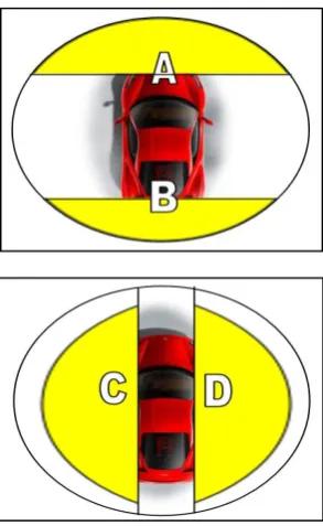
These sensors are located near the right front wheel and left rear wheel, in order to detect any vibration around the car. To be capable of capturing the whole scene, four cameras were used in the prototype to cover all four sides each covering one side of the car. In Figure 3, A, B, C and D represent the positions of these cameras.
6.
RESULT AND ANALYSIS
The intelligent car security system was built to be of high accuracy, robustness, secure and also to be convenient to the users, so as to ensure that the system meets the user requirements. Thirty tests have been carried out in day light and low light conditions. A total of sixty incidents have been made and tested at different angles of the car. The results were analyzed using four performance parameters. Displaying of car license plate in the picture is considered as the most important parameter. The other parameters used are coverage of car angles and the overall perceived clarity of the picture. Capturing the picture of the third party who made the incident is also taken as a parameter, though not very important.
The accuracy index of the system is evaluated by giving different weights for each parameter according to its importance. The parameter ‘display of license plate in the picture’ is given 50% weight being the most important one, because it identifies the plate details of car that is responsible for the incident.The ‘coverage of car angles’ parameter is determined by sensors which are kept at all sides of the car and sense any damage to the car, so it is given 35% weight.
The ‘overall perceived clarity of picture’ is given 10% weight. Capturing the picture of the third party who made the incident is given 5% weight as it is the least important parameter. The various parameters and their weights are given in Table 1.
Table 1: Performance Parameters
No. Parameter
Percentage of Importance
1 Display of License Plate in the
Picture 50%
2 Coverage of all Sides 35%
3 Overall Clarity of the Picture 10%
4 Display of the Third Party
Driver in the Picture 5%
The result of the first parameter ‘display of license plate’ is further divided into 3 types as given in Table 1, according to perceived quality of numbers and alphabets in the plate to make the system simple and cheap:
Type 1-Good, if both numbers and alphabets on the plate are easily readable.
Type 2-Average, if either number or the alphabets on the plate are readable.
Type 3-Poor, if both of them are not readable.
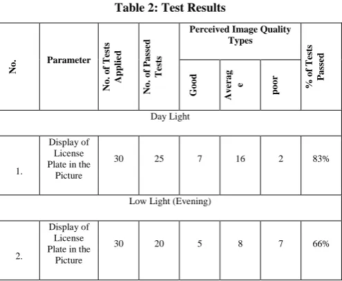
The No. of the Passed Tests is less than the overall Applied Tests due to the quality of used camera and its position. The No. of the Passed Tests at Day time is more than the No. of the Passed Tests at the Evening Time (low Light) because the camera does not support the Night-Vision mode.
The Percentage of Passed Tests at Table 2 is calculated by dividing the No. of Applied Tests to the No. of the Passed Tests.
Table 2: Test Results
No.
Parameter
No.
of
T
es
ts
App
li
e
d
No.
of
P
as
se
d
T
es
ts
Perceived Image Quality Types
%
of
T
es
ts
P
as
se
d
Good Ave rag e
p
oor
Day Light
1.
Display of License Plate in the
Picture
30 25 7 16 2 83%
Low Light (Evening)
2.
Display of License Plate in the
Picture
30 20 5 8 7 66%
The Accuracy Index ( ) of the system is calculated by the following equation:
Using the Test Result from Table 3 and the above equation, the accuracy index for the day time (light view) and for the low light have been calculated as follows:
Thus the accuracy index of the system at day light conditions is 88.5% and at low-light conditions is 74.16% and the Overall Accuracy Index (O ) of the system is 81.3% which is calculated by using the following equation:
O = ( + ) / 2.
Table 3: Test Results
No.
Parameter
No.
of
T
es
ts
App
li
e
d
No.
of
P
as
se
d
T
es
ts
No.
of
F
ail
T
es
ts
%
of
T
es
ts
P
as
se
d
Day Light
1.
Covering All Sides of the
Car
30 30 0 100%
2. Overall Clarity
of the Picture 30 30 0 100%
3.
Display of the Third Part in
the Picture
30 15 15 50%
Low Light (Evening)
4. Covering All
Car Sides 30 30 0 100%
5. Overall Clarity
of the Picture 30 16 7 53.3%
6.
Display of the Car Driver in the Picture
30 5 25 16.6%
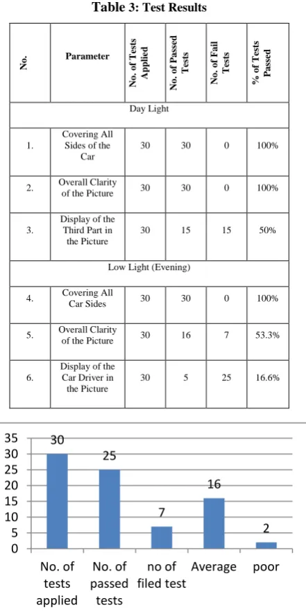
Figure 4.1: Display of License Plate in the Picture - Day Light
To analyse the result more, separate graphswere drawn for each case.
From figures 4.1 to 4.5,it can be observed that, the camera is working in day light conditions better than in low light conditions. This is clearly displayed in the test results as the day light display clarity of the picture has scored 100% results ; whereas, in low light conditions the clarity results were 53.3%. This means that the camera that is being used is not supporting low light mode and it indicates the necessity of providing a support to the night camera mode. And this shortcoming can also be overcome and the system can be improved if we change the type and location of the camera.
Figure 4.2 Display of License Plate in the Picture - Low Light
Figure 4.3 Covering all Car Sides
Figure 4.4 Overall Clarity of the Picture - Day Light
The Figure 4.3 is testing the sensor sensitivity. For the Figure can say the sensors are working perfect and it is detecting any vibration in all co education that represent by passing 100%. 30
25
7
16
2 0
5 10 15 20 25 30 35
No. of tests applied
No. of passed tests
no of filed test
Average poor
30
20
5 8 7
0 5 10 15 20 25 30 35
No. of tests applied
No. of passed
tests
Good Average poor
30 30
0 0
5 10 15 20 25 30 35
No. of tests applied
No. of passed tests
no of filed test
30 30
0 0
5 10 15 20 25 30 35
No. of tests applied
No. of passed tests
Figure 4.5 Overall clarity of the picture - Low light
Figures 4.6 & 4.7 is about display the third part ‘diver of the second car’. That test is passing in low percentage which is 50% in day light and 25% in low light. The less percentage is according to side of heating because some time the third part may he/she driving reverse mode. But still if using camera supporting evening view the percentage of low light will be increasing.
Figure 4.6 Display of the Third Part in the Picture - Day Light
Figure 4.7 Display of the Third Part in the Picture - Low Light
7.
CONCLUSION
The main objective of this project was to develop an intelligent car security system that will prevent cars from theft attempts and give vital information including pictures of crashing incidents that happen at parking lots due to careless parking. The system is easy to use and provides information without the need for human involvement. This system helps the car user to know about any crash at the parking lot by
sending the information to his/her smart phone which are captured by the sensors and the cameras. In the event of theft, the location of car can be identified with the help of GPS tracking which is built in the system. The system is secure, reliable, flexible and affordable. Results based on a number of tests conducted at different conditions show that the system is giving accurate results most of the time. Further, it is observed that the accuracy index of the system at day light is better than at low light conditions. In our future work it is proposed to capture not only still pictures, but also short video of the incident as an enhancement to the system, and high camera quality and withhigh resolution night-vision capabilities will be used and at different positions is going to be implemented. The No. of the cameras will be increase. The other area of future work is trying to reduce the interference between the transmitters from different cars that has many ways to achieve but it is recommended by designing directional antennas or special type of signal jammers. The GSM modem can be upgraded with GPRS or 3G capabilities so that a low resolution picture or video clip of the incident or the intruder could be sent to the car owner.
8.
ACKNOWLEDGMENTS
We thank the management of Caledonian College of Engineering, Oman for providing all the facilities for undertaking this project successfully
9.
REFERENCES
[1] Tang, V., Zheng, Y. & Cao, J., 2006. An Intelligent Car Management System based on Wireless Sensor Networks. 1st International Symposium on Pervasive Computing and Applications. Hong Kong, Wednesday 4th March 2009. Hong KongPolytechnic University: IEEE.pp. 65-70.
[2] Al-Absi, H., Sebastian, P., Devaraj, J. &Voon Y., Vision-Based Automated Parking System. 10th Internation Conference on Information Science, Signal Processing and their Applications., Kuala Lumpur, Malaysia 2011.
[3] Rashidi, F., Ariff, M., & Ibrahim M.. Car Monitoring using Bluetooth Security System .International conference on Electronic, Control and computer Engineering. Pahang, Malaysia, 2011.
[4] Seshasayee, V. &Manikandan, E., 2013, Automobile Security System Based on Face Recognition Structure Using GSM Network.Advance in Electronic and Electric Engineering. 3 (6). P. 733-738.
[5] Shah, R. &Gharge, A., 2012. GSM Based Car Security System. International Journal of Engineering and Innovation Technology. 2. P. 203-206
[6] A. Jadhav, and P. Gadhari, “Interactive Voice Response (IVR) and GSM Based Control System”. Proceedings of the National Conference "NCNTE-2012". Mumbai. 2012
[7] India yellow pages, 2014.Pantagone satellite Bhopal.
[Online] Available from:
http://www.indianyellowpages.com/pantagone-satellite-bhopal/products.htm?slno=257962. [Accessed :5th May 2012].
[8] Miguel A., Porta G., Jose A., Estufillo S., & y Moises Sanchez A., 2006.Bluetooth/GMRS Car Security System with a Randomly Located Movement.Electronics, 30
16 14
0 5 10 15 20 25 30 35
No. of tests applied
No. of passed tests
No. of filed test
30
15 15
0 5 10 15 20 25 30 35
No. of tests applied
No. of passed tests
no of filed test
30
5
25
0 5 10 15 20 25 30 35
No. of tests applied
No. of passed tests
Robotics and Automotive Mechanics.Washington, 2006.IEEE Computer SocietyWashington, DC, US.
[9] P. Rigole, et al., “Component-based infrastructure for pervasive user interaction”. Proceedings of Software Techniques for Embedded and Pervasive Systems., 2005.
[10]J. Nichols, et al., “Generating Remote-Control interfaces for Complex Appliances”. Proceedings of the ACM
Conference of User-Interface software and Technology (UIST02), ACM press, pp. 161-170, 2002.