Single variable new first-order shear deformation theory for isotropic
plates
Abstract
This paper presents a single variable new first-order shear deformation plate theory with only one fourth-order partial governing differential equa-tion. It may be noted that, first-order shear deformation plate theory of Mindlin has three coupled partial governing differential equations involv-ing three unknown functions. Even a recently developed new first-order shear deformation plate theory has two uncoupled partial governing dif-ferential equations involving two unknown functions for static problems. The displacement functions of the proposed theory give rise to constant transverse shear strains through thickness of the plate and, as is the case of Mindlin plate theory, the proposed theory also requires a shear correction factor. The governing differential equation, expressions for moments and shear forces of the proposed theory have a striking resemblance to the cor-responding expressions of classical plate theory. The proposed theory is the only first-order shear deformation plate theory with two different types of physically meaningful clamped boundary conditions. To obtain so-lutions for the flexure of the plate, efforts required using the proposed the-ory are comparable to those involved in the case of classical plate thethe-ory. The effectiveness of the proposed theory is demonstrated through illustra-tive examples and by comparing results obtained with other plate theories.
Keywords
Single variable plate theory, shear deformation plate theory.
1 INTRODUCTION
The simplest plate theory is classical plate theory (CPT) which was developed in the late 19th century. It has been widely used as a first level check for analysis of structures that can be approximated as plates. However, CPT
does not take into account the effects of transverse shear deformations present through the plate thickness. These effects of shear in plate deformations are significant especially in case of thick plates. Hence, CPT can provide rea-sonably accurate results only for thin plates. Use of CPT provides underestimated deflections and overestimated frequencies and buckling loads for thick plates (Ghugal and Shimpi (2002)).
To address these drawbacks of CPT, Reissner (1945) and Mindlin (1951) introduced first-order shear de-formation plate theories. Displacement based Mindlin plate theory assumes constant transverse shear strains through the plate thickness and requires a shear correction factor. Even though the use of Mindlin plate theory provides satisfactory results for analysis of thick plates, it involves three coupled partial governing differential equations involing three unknown functions. It also requires specification of three boundary conditions per edge as opposed to CPT which requires specification of only two boundary conditions per edge.
Recently, Shimpi et al. (2007) developed new first-order shear deformation plate theories (NFSDT). NFSDT
involves two partial governing differential equations involving two unknown functions. These two equations are inertially and elastically uncoupled in case of static problems. Whereas, these two equations are only inertially coupled and elastically uncoupled in case of dynamics problems. As is the case of Mindlin plate theory, NFSDT
also requires specification of three boundary conditions per edge.
The objective of this paper is to present a single variable new first-order shear deformation theory for iso-tropic plates with only one partial governing differential equation. In this regards, Senjanović et al. (2013) have also derived fourth-order partial governing differential equation for moderately thick plate vibrations. It must be noted that the proposed theory is based on NFSDT by Shimpi et al. (2007) and refined plate theory (RPT) by Shimpi (2002). It is evident from equations (9), (10) and (20) of Senjanović et al. (2013) that they have also used
Rameshchandra P. Shimpia* P. J. Guruprasada
Kedar S. Pakharea
a Department of Aerospace Engineering, Indian Institute of Technology Bombay, Mumbai, India, 400076. E-mail: [email protected], [email protected], [email protected]. * Corresponding author
http://dx.doi.org/10.1590/1679-78254842 Received January 19, 2018
the key concepts of NFSDT. They have developed the plate theory for thick plate vibrations only. The proposed theory is a displacement based theory for the plate flexture. Unlike any other first-order shear deformation plate theory, the proposed theory describes two different types of physically meaningful clamped boundary conditions which are analogous to those discussed by Timoshenko and Goodier (1951) in the context of two-dimensional theory of elasticity approach for beam analysis. As opposed to Mindlin plate theory, the proposed theory requires specification of only two boundary conditions per edge.
2 NOTATIONS USED
The notations used in this paper for displacements (u, v, w); direct strains (x, y, z); shear strains (xy, yz
, zx); direct stresses (x, y, z) and shear stresses (xy, yz, zx) of the plate are the same as the one used by Timoshenko and Goodier (1951) on page no. xvii and xviii.
3 PLATE UNDER CONSIDERATION
The following are the features of the plate under consideration: 1. The plate considered is as shown in Figure 1 and it has uniform thickness h.
2. The plate is made of linearly elastic, homogeneous, isotropic material. Modulus of elasticity E, modulus of rigidity G and Poisson’s ratio of the plate material are related by G E / [2(1)].
3. Area Ω
x y,
is the mid-surface of the undeformed plate which is enclosed by a boundary curve
x y,
; as shown in Figure 1. 4. The right handed Cartesian co-ordinate system 0 x y z would be utilized throughout this paper.a. The xy plane of this co-ordinate system is assumed to coincide with mid-surface of the undeformed plate.
b. The origin “0” of this co-ordinate system can be selected at a convenient location on the mid-surface of the undeformed plate.
5. The plate is loaded on its surface z h/ 2 by a transverse load of intensity q x y
,
. The loading is considered as positive when it acts in the positive direction of z axis.6. Local directions n, s and z' at a typical point ‘P’ on the edge are as shown in Figure 1. n and s are normal and tangent respectively to a boundary curve at that point. Direction z' is parallel to the z axis of co-ordinate system. Physically meaningful boundary conditions can be prescribed at the boundary of the plate in terms of such local co-ordinate systems.
Figure 1: Geometry of the plate.
4 ASSUMPTIONS MADE IN THE PRESENT THEORY
Assumptions of the present theory are built on those of Shimpi et al. (2007).
1. Displacements involved are small in comparison to the plate thickness. Hence, strains produced in the plate are infinitesimal.
3. Transverse normal perpendicular to the mid-surface of the plate before deformation, remains straight but may or may not remain normal to the mid-surface of the plate after deformation.
4. Following points should be noted regarding displacement functions of the present theory: a. The transverse displacement w along the z direction consists of two components:
i. Bending component wb ii. Shear component ws
These two components are functions of x and y co-ordinates only.
b. In-plane displacement u along the x direction and in-plane displacement v along the y direction are analogous to those of
CPT.
c. In-plane displacements u and v in conjunction with bending component wb (of transverse displacement w) do not contribute towards transverse shear strains. Shear component ws (of transverse displacement w) alone contributes towards transverse shear strains. These transverse shear strains remain constant across the plate thickness.
5. As is the case with Mindlin plate theory (Mindlin (1951)), the present theory assumes transverse shear strains yz and zx to remain constant through the plate thickness. It is well known fact that, in reality, these transverse shear strains vary, more or less, in parabolic manner through the plate thickness. Hence, a shear correction factor associated with Mindlin plate theory (Mindlin (1951)) will be utilized in the present theory.
5 EXPRESSIONS FOR DISPLACEMENTS OF THE PRESENT THEORY
As a result of assumption 1, strain-displacement relations of linear theory of elasticity will hold good.
; ;
x y z
u v w
x y z
; ;
xy yz zx
v u w v u w
x y y z z x
(1)
As a result of assumption 2, constitutive relations between stresses and strains can be used to relate direct stresses x and y to linear strains x and y as follows:
2 1
x x y
E
(2)
2 1
y E y x
(3)
As a result of assumption 3 and assumption 4, expressions for in-plane displacements u and v of the present theory can be written as follows:
( , , ) wb
u x y z z
x
(4)
( , , ) wb
v x y z z y
(5)
The transverse displacement w has a bending component wb and a shear component ws. Hence, ( , )x y = wb( , )x y + w xs( , )y
w (6)
With some efforts, shear component ws can be expressed in terms of bending component wb (as shown in Appendix A) as:
2 2
2
2 2
6 (1 )
b b
s
w w
h w
k x y
Here, ‘k’ is a shear correction factor which is analogous to shear correction factor proposed by Mindlin (1951).
Hence, transverse displacement w can be expressed in terms of bending component wb as follows:
2 2
2
2 2
6 (1 )
b b
b
w w
h
w w
k x y
(8) It can be observed from expressions (4), (5) and (8) that expressions for in-plane displacements u and v, and transverse displacement w contain only one unknown variable, i.e. wb.
Now, using displacement functions of the present theory in strain-displacement relations given by equation (1), expressions for strains can be written as follows:
2 2 b x w z x (9) 2 2 b y w z y (10) 2 2 b xy w z x y
(11)
2 2
2
2 2
6 ( )
1 b b yz w w h
k y x y
(12)
2 2
2
2 2
6 ( )
1 b b zx w w h
k x x y
(13)
From expressions (12) and (13), it can be observed that, as is the case with Mindlin plate theory (Mindlin (1951)), transverse shear strains yz and zx remain constant through the plate thickness in the present theory. Hence, transverse shear stresses yz and zx also remain constant through the plate thickness.
It is well known fact that, in reality, transverse shear stresses yz and zx vary, more or less, in parabolic manner through the plate thickness. In general, these transverse shear stresses are zero on surfaces (z h/ 2)
of the plate. Hence, a shear correction factor associated with Mindlin plate theory (Mindlin (1951)) will be uti-lized in the present theory.
6 MODIFIED CONSTITUTIVE RELATIONS OF THE PRESENT THEORY
The constitutive relations of theory of elasticity in respect of shear strains and shear stresses are xy Gxy, yz G yz
and zx Gzx . However as a result of assumption 3 and assumption 5, the relations between trans-verse shear strains and transtrans-verse shear stresses get modified by incorporating a shear correction factor ‘k’ as:
yz kG yz
and zx kGzx . Hence, constitutive relations between stresses and strains can be written as fol-lows:
2 1
x x y
E
(14)
2 1
y E y x
1
2 ( )
xy xy E (16) (
2 1 )
yz yz E k (17) (
2 1 )
zx zx E k (18)
7 EXPRESSIONS FOR STRESSES
Now, using equations (9) through (13) in constitutive relations given by equations (14) through (18), ex-pressions for stresses can be written as follows:
2 2
2 2 2
1
b b x
E z w w
x y
(19)
2 2
2 2 2
1
b b y
E z w w
y x
(20)
2
2(1 )
1
b xy
E z w
x y (21)
2 2 2
2 2 2
12 (1
)
b b
yz
E h w w
y x y
(22)
2 2 2
2 2 2
12 (1
)
b b
zx
E h w w
x x y
(23)
8 EXPRESSIONS FOR MOMENTS AND SHEAR FORCES
Moments Mx, My and Mxy; shear forces Qx and Qy can now be defined as follows:
/2 /2 x y z h xy z h z x y xy x y x yz z z z z M M M d Q Q
(24)2 2 2 2 b b x w w M D
x y
(25)
2 2 2 2 b b y w w M D
y x
(26)
2
(1 ) b xy w M D x y (27) 2 2 2 2 b b x w w Q D
x x y
(28)
2 2 2 2 b b y w w Q D
y x y
(29)
Here, D represents the rigidity of the plate which is given by
3 2 12 1 E h D (30) It can be observed that expressions for moments given by equations (25), (26), (27) and shear forces given by equations (28), (29) have striking resemblance to those of CPT.9 OBTAINING GOVERNING DIFFERENTIAL EQUATION FOR THE FLEXURAL ANALYSIS OF THE PLATE
The equilibrium equations as per three-dimensional linear theory of elasticity can be written as follows:
0
xy
x xz
x y z
(31)
0
yx y yz
x y z
(32)
0
zy
zx z
x y z
(33)
Here in equations (31) through (33), body forces (such as self weight due to gravity) are not mentioned sep-arately as they can be merged with externally applied loads without causing much loss of accuracy. It is important to note that, theory of elasticity equations can be satisfied only in case of few problems. Whereas, gross equilibri-um equations can be satisfied comparatively easily. Gross equilibriequilibri-um equations can be obtained using theory of elasticity equilibrium equations (31) through (33) as obtained by Shimpi (2002).
0 xy x x M M Q x y
(34)
0 yx y y M M Q x y
0
y
x Q
Q
q
x y
(36)
Equations (34), (35) and (36) are gross equilibrium equations. Expressions for moments given by equations (25), (26), (27) and shear forces given by equations (28), (29) satisfy gross equilibrium equations (34) and (35).
It must be noted that, shear forces Qx and Qy as given by expressions (28) and (29) respectively are ob-tained using expression for ws as given by equation (7); displacement functions (4), (5) and (6); strain-displacement relation (1); stress-strain relation (17) and (18); expressions for Qx and Qy as given in equation (24). Expressions for Qx and Qy which are identical to expressions (28) and (29) can also be obtained using ex-pressions for moments Mx, My and Mxy as given by equations (25), (26) and (27) respectively in gross equilib-rium equations (34) and (35) (as shown in Appendix A).
Now, using expressions for shear forces Qx and Qy as given by expressions (28) and (29) in gross equilibri-um equation (36), governing differential equation for the flexural analysis of the plate can be obtained as follows:
4 4 4
4 2 2 2 4
b b b
w w w q
D
x x y y
(37) Here, it can be observed that, governing differential equation (37) of the present theory has striking resem-blance to the governing differential equation of CPT. The only difference is that, in equation (37), wb is appearing, whereas in case of CPT, in its place transverse displacement w appears.
Using governing differential equation (37) and appropriate boundary conditions, wb can be obtained. Trans-verse displacement w can be obtained using equation (8).
The appropriate physically meaningful boundary conditions would now be discussed.
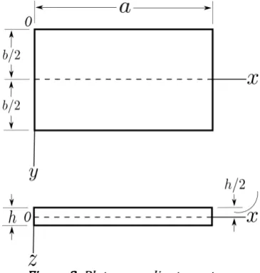
Figure 2: Plate co-ordinate system.
10 BOUNDARY CONDITIONS
In this section, few commonly used physically meaningful boundary conditions would be discussed for the rectangular plate (Figure 2) at the edge
2
b
y , for the sake of illustration. To prescribe the boundary conditions
at other edges, i.e.
2
b
y , x 0 and x a, one could follow the similar logic as that of the edge
2
b
y . In case of the plate with arbitrary shape, boundary conditions can be specified in similar manner by considering local direc-tions n, s and z' at a typical point ‘P’ on the edge as shown in Figure 1.
1. Plate edge
2
b
y is simply-supported
At simply-supported edge
2
b
y , transverse displacement w is zero and bending moment My is zero.
2 2
2
/2 2 2
/2
( 0
6 1 )
b b b y b y b w w h w w
k x y
(38)
2 2
/2 2 2
/2
b b 0
y y b
y b
w w
M D
y x
(39)
Expressions (38) and (39) lead to following boundary conditions at simply-supported edge
2
b y :
/2 0
b y b w
(40)
2 2 /2 0 b y b w y
(41)
2. Plate edge
2
b
y is free:
At free edge
2
b
y ; using same reasoning as that in the case of CPT for free edge as discussed by Timoshen-ko and Woinowsky-Krieger (1959) on page no. 83 through 85, boundary conditions can be specified as follows:
2 2
/2 2 2
/2
b b 0
y y b
y b
w w
M D
y x
(42)
3 3
3 2
/2 /2
(2 ) 0
xy b b
y
y b y b
M w w
Q D
x y x y
(43)
3. Plate edge
2
b
y is clamped:
At clamped edge
2
b
y ; it is feasible to represent two types of boundary conditions. In this paper, these two types of clamped boundary conditions are denoted as “clamped edge: type 1” and “clamped edge: type 2”. These boundary conditions are analogous to those discussed by Timoshenko and Goodier (1951) on page no. 35 through 39 in the context of two-dimensional theory of elasticity approach for beam analysis.
a. Plate edge
2
b
For “clamped edge: type 1” boundary conditions on the edge
2
b
y , w is taken as zero and slope v
z is tak-en as zero at the clamped edge
2
b
y . This slope, can be expressed in terms of wb by using equation (5). Hence, following conditions are to be used:
2 2
2
/2 2 2
/2
( 0
6 1 )
b b b y b y b w w h w w
k x y
(44)
/2 0 b y b w y
(45)
b. Plate edge
2
b
y is clamped with “clamped edge: type 2”
For “clamped edge: type 2” boundary conditions on the edge
2
b
y , the displacement boundary condition
remains the same as that of earlier case, but now slope w y
is taken as zero at the clamped edge 2 b
y , Hence, following conditions are to be used:
2 2
2
/2 2 2
/2
0
6 (1 )
b b b y b y b w w h w w
k x y
(46)
2 2
2
2 2
/2 /2
0
6 (1 )
b b b
y b y b
w w w
w h
y y k y x y
(47)
It can be seen from the boundary condition given by equation (45) that at the clamped edge
2
b
y , slope of
only bending component wb (of transverse displacement w) along y axis is equal to zero. Hence in case of “clamped edge: type 1” boundary condition, effects of shear deformation on transverse displacement are signifi-cant.
Whereas, it can be seen from the boundary condition given by equation (47) that at the clamped edge
2
b y , slope of transverse displacement w along y axis is equal to zero. Hence in case of “clamped edge: type 2” boundary condition, effects of shear deformation on transverse displacement are less significant as compared to those of “clamped edge: type 1” boundary condition.
It is pointed out by Groh and Weaver (2015) that inconsistencies with regards to the shear force arise in the formulation of flexural behaviour of plates with clamped boundary conditions using a certian class of axiomatic shear deformation theories. Discussion provided by Groh and Weaver (2015) points out that shear forces errone-ously vanish at a clamped edge when the constitutive relations and boundary conditions of the particular theory are utilized. Hence, the shear forces obtained by using the equilibrium considerations of the forces would not match with those obtained using constitutive relations and boundary conditions of the particular theory. Hence, this would result in the inconsistency of the shear forces.
11 COMMENTS ON THE PRESENT THEORY
The following are the noteworthy features of the present theory:
1. The proposed theory is a displacement based theory. As is case of Mindlin plate theory (Mindlin (1951)), the present theory assumes constant transverse shear strains across the plate thickness and it requires a shear correction factor to be specified. The governing differential equation of the present theory is obtained by utilizing gross equilibrium equations of the plate. These gross equilibrium equations are in terms of moments, shear forces and the applied loading. Based on physical understanding, the boundary conditions have been specified.
2. In the present theory, shear strains are obtained using assumed displacement functions along with strain-displacement relations. These shear strains are then used to obtain shear stresses using modified stress-strain relations. These shear stresses are finally used to obtain shear forces. Whereas, in case of CPT, shear forces are obtained using gross equilibrium equations.
3. Unlike Mindlin plate theory (Mindlin (1951)) which contains three coupled partial governing differential equations and three unknown functions, the present theory has only one fourth-order partial governing differential equation (equation (37)). The present theory
involves only one unknown function (wb).
4. For the plate flexure problems, the expressions for moments, shear forces and the governing differential equation of the present theory
have striking resemblance to those of CPT. The only difference is that, in the present theory, wb appears in these expressions, whereas in case of CPT, in its place transverse displacement w appears.
5. Unlike any other first-order shear deformation theory, the present theory provides two different types of physically meaningful clamped boundary conditions. These clamped boundary conditions of the present theory are analogous to those discussed by Timoshenko and Goodier (1951) in the context of two-dimensional theory of elasticity approach for beam analysis.
6. Following points should be noted with regards to the present theory, the work presented by Shimpi et al. (2017) and the conceptual differences between them:
a. The difference between the present theory and the work presented by Shimpi et al. (2017) in their eqs. (46) - (48) is on similar lines as the difference between NFSDT by Shimpi et al. (2007) and RPT by Shimpi (2002). In other words, the present theory belongs to the category of first-order shear deformation plate theories. Whereas the work presented by Shimpi et al. (2017) belongs to the category of higher-order shear deformation plate theories.
b. It should be noted that in case of both Shimpi et al. (2017) in their eq. (48) and the present theory, transverse displacement w
consists of a bending component wb and a shear component ws. But on similar lines of RPT, the assumed in-plane displacement field of Shimpi et al. (2017) in their eqs. (46) - (47) has linear as well as cubic variations in terms of the plate thickness coordinate. Whereas on the similar lines of NFSDT, the assumed in-plane displacement field of the present theory has only linear variation in terms of the plate thickness coordinate.
12 ILLUSTRATIVE EXAMPLE
In this section, illustrative examples for the flexure of an isotropic rectangular plates will be presented to demonstrate the effectiveness of the present theory.
Strategy for solutions
All the illustrative examples involve rectangular plates as shown in Figure 2. The plate is simply-supported on the edges x 0 and x a. For individual problems, the boundary conditions at the edges
2
b y and
2
b y
would be specified. The plate is acted upon by uniformly distributed load of intensity qo per unit area over the entire surface
2
b
z of the plate and the load qo acts in the positive z direction.
For such a plate, it is possible to obtain expression for wb using Lévy method of analysis as discussed by Ti-moshenko and Woinowsky-Krieger (1959) on page no. 113 through 115. This expression for wb satisfies simply-supported boundary conditions on the edges x 0 and x a as well as the governing differential equation (37). Expression for wb is as follows:
5 5 4
1,3,5,..
4 cosh sinh
sin
sinh cosh
m m
o b
m
m m
m y m y m y
A B
a a a
m
q a m x
w
D a
m y m y m y
C D
a a a
5 5 4 1,3,5,.. 4 cosh sinh sinh cosh m m m m o m
m y m y m y
A B
a a a
m
m y m y m y
C D
a a a
q a w D h a
5 52 2 2
sin
2 cosh
3 (1 )
sinh m m m x a m y B a m m k m y D a
(49)
Now, arbitrary constants Am, Bm, Cm and Dm are obtained by substituting expressions (48) and (49) into appropriate boundary conditions of remaining two edges i.e.
2
b y and
2
b
y and by solving obtained set of linear algebraic equations.
1. Example 1: Plate with edges
2
b y ,
2
b
y , x 0 and x aare all simply-supported (SSSS).
2. Example 2: Plate with edges
2
b y ,
2
b
y are clamped and edges x 0, x a are simply-supported (SCSC).
3. Example 3: Plate with edges
2
b y ,
2
b
y are free and edges x 0, x a are simply-supported (SFSF).
4. Example 4: Plate with edge
2
b
y is clamped, edge
2
b
y is simply-supported and edges x 0, x a are simply-supported
(SCSS).
5. Example 5: Plate with edge
2
b
y is clamped, edge
2
b
y is free and edges x 0, x a are simply-supported (SCSF).
6. Example 6: Plate with edge
2
b
y is simply-supported, edge
2
b
y is free and edges x 0, x a are simply-supported (SSSF). As pointed out by Lee et al. (2002), in the open literature, the only analytical Mindlin plate results on Lévy plates have been reported by Cooke and Levinson (1983). Most of the results present in the literature for the plate flexure problems pertain to SSSS, SCSC and SFSF plates. Hence for examples 4, 5 and 6, authors have com-pared the results for SCSS, SCSF and SSSF plates obtained using the present theory with corresponding results given by Zenkour (2003), Thai and Choi (2013) and Thai et al. (2013). Zenkour (2003) has used mixed plate the-ory, Thai and Choi (2013) have used refined plate theory and Thai et al. (2013) have used simple refined shear deformation theory for the plate flexure analysis.
In example 1; m 1, 3, 5, ...., 49 is taken, whereas for examples 2, 3, 4, 5 and 6; m 1, 3, 5, 7 is taken for series expansion of wb and w.
13 NUMERICAL RESULTS AND DISCUSSIONS
Using expressions (48) and (49) for wb and w respectively, numerical results will now be presented for flex-ural analysis of SSSS, SCSC, SFSF, SCSS, SCSF and SSSF plates. Numerical results in terms of non-dimensional transverse displacement (w), non-dimensional bending moment (Mx) and non-dimensional shear force (Qx) obtained using the present theory and corresponding results available in the literature are tabulated in Tables 1 through 6.
Poisson’s ratio () for the plate material is assumed to be 0.3. The value of shear correction factor (k) is taken as 5/6.
The non-dimensional parameters used in the tabulation are defined as follows:
4
o wD w
q a
: Non-dimensional transverse displacement (in the context of SSSS, SCSC, SFSF, SCSS, SCSF and SSSF
plates carrying uniformly distributed loads).
2 x x
o M M
q a
: Non-dimensional bending moment (in the context of SSSS plates carrying uniformly distributed
loads). x x
o Q Q
q a
: Non-dimensional shear force (in the context of SSSS plates carrying uniformly distributed loads).
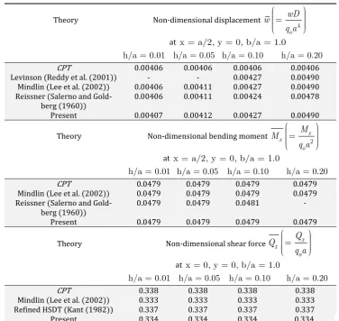
Table 1: Comparison of various non-dimensional parameters of the plate with SSSS boundary conditions (Example 1) and carrying a uniformly distributed load of intensity qo and Poisson’s ratio (
= 0.3).Theory Non-dimensional displacement 4 o wD w
q a
at x = a/2, y = 0, b/a = 1.0
h/a = 0.01 h/a = 0.05 h/a = 0.10 h/a = 0.20
CPT 0.00406 0.00406 0.00406 0.00406
Levinson (Reddy et al. (2001)) - - 0.00427 0.00490 Mindlin (Lee et al. (2002)) 0.00406 0.00411 0.00427 0.00490 Reissner (Salerno and
Gold-berg (1960)) Present
0.00406
0.00407
0.00411
0.00412
0.00424
0.00427
0.00478
0.00490
Theory Non-dimensional bending moment x x2 o M M
q a
at x = a/2, y = 0, b/a = 1.0
h/a = 0.01 h/a = 0.05 h/a = 0.10 h/a = 0.20
CPT 0.0479 0.0479 0.0479 0.0479
Mindlin (Lee et al. (2002)) 0.0479 0.0479 0.0479 0.0479 Reissner (Salerno and
Gold-berg (1960)) 0.0479 0.0479 0.0481 -
Present 0.0479 0.0479 0.0479 0.0479
Theory Non-dimensional shear force x x o Q Q
q a
at x = 0, y = 0, b/a = 1.0
h/a = 0.01 h/a = 0.05 h/a = 0.10 h/a = 0.20
CPT 0.338 0.338 0.338 0.338
Mindlin (Lee et al. (2002)) 0.333 0.333 0.333 0.333 Refined HSDT (Kant (1982)) 0.337 0.337 0.337 0.337
Table 2: Comparison of non-dimensional displacements of the plate with SCSC boundary conditions (Example 2) and carrying a uniformly distributed load of intensity qo and Poisson’s ratio (
= 0.3).Theory Non-dimensional displacement 4 o wD w q a
at x = a/2, y = 0, b/a = 1.0
h/a = 0.01 h/a = 0.05 h/a = 0.10 h/a = 0.20
CPT 0.00192 0.00192 0.00192 0.00192
Levinson (Reddy et al.(2001)) - - 0.00227 0.00322 Mindlin (Lee et al. (2002)) 0.00192 0.00199 0.00221 0.00302 Reissner (Salerno and
Gold-berg (1960)) Present clamp type 1 Present clamp type 2
0.00192 0.00192 0.00192 0.00199 0.00199 0.00193 0.00220 0.00222 0.00196 0.00298 0.00308 0.00210
Theory Non-dimensional displacement 4 o wD w q a
at x = a/2, y = 0, b/a = 2.0
h/a = 0.01 h/a = 0.05 h/a = 0.10 h/a = 0.20
CPT 0.00845 0.00845 0.00845 0.00845
Levinson (Reddy et al.(2001)) - - 0.00889 0.01013 Mindlin (Lee et al. (2002)) 0.00845 0.00855 0.00885 0.01000 Reissner (Salerno and
Gold-berg (1960)) Present clamp type 1 Present clamp type 2
0.00845 0.00845 0.00845 0.00854 0.00855 0.00850 0.00882 0.00886 0.00867 0.00985 0.01005 0.00936
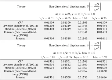
Table 3: Comparison of non-dimensional displacements of the plate with SFSF boundary conditions (Example 3) and carrying a uniformly distributed load of intensity qo and Poisson’s ratio (
= 0.3).Theory Non-dimensional displacement 4 o wD w q a
at x = a/2, y = 0, b/a = 1.0
h/a = 0.01 h/a = 0.05 h/a = 0.10 h/a = 0.20
CPT 0.01309 0.01309 0.01309 0.01309
Levinson (Reddy et al.(2001)) 0.01310 0.01319 0.01346 0.01454 Mindlin (Lee et al. (2002)) 0.01310 0.01319 0.01346 0.01454 Reissner (Salerno and
Gold-berg (1960)) Present - 0.01310 - 0.01318 0.01341 0.01342 0.01433 0.01441
Theory Non-dimensional displacement 4 o wD w q a
at x = a/2, y = b/2, b/a = 1.0
h/a = 0.01 h/a = 0.05 h/a = 0.10 h/a = 0.20
CPT 0.01501 0.01501 0.01501 0.01501
Levinson (Reddy et al.(2001)) 0.01504 0.01522 0.01560 0.01690 Mindlin (Lee et al. (2002)) 0.01504 0.01522 0.01560 0.01690 Reissner (Salerno and
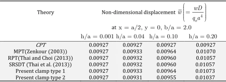
Table 4: Comparison of non-dimensional displacements of the plate with SCSS boundary conditions (Example 4) and carrying a uniformly distributed load of intensity qo and Poisson’s ratio (
= 0.3).Theory Non-dimensional displacement 4 o wD w
q a
at x = a/2, y = 0, b/a = 2.0
h/a = 0.001 h/a = 0.04 h/a = 0.10 h/a = 0.20
CPT 0.00927 0.00927 0.00927 0.00927
MPT(Zenkour (2003)) 0.00927 0.00933 0.00964 0.01070 RPT(Thai and Choi (2013)) 0.00927 0.00932 0.00960 0.01057
SRSDT (Thai et al. (2013)) Present clamp type 1 Present clamp type 2
0.00927 0.00927 0.00927
0.00932 0.00933 0.00931
0.00960 0.00964 0.00955
0.01057 0.01073 0.01037 MPT: Mixed plate theory, RPT: Refined plate theory, SRSDT: Simple refined shear deformation theory.
Table 5: Comparison of non-dimensional displacements of the plate with SCSF boundary conditions (Example 5) and carrying a uniformly distributed load of intensity qo and Poisson’s ratio (
= 0.3).Theory Non-dimensional displacement 4 o wD w
q a
at x = a/2, y = 0, b/a = 2.0
h/a = 0.001 h/a = 0.04 h/a = 0.10 h/a = 0.20
CPT 0.01061 0.01061 0.01061 0.01061
MPT(Zenkour (2003)) 0.01061 0.01066 0.01098 0.01209 RPT(Thai and Choi (2013)) 0.01061 0.01066 0.01095 0.01197
SRSDT (Thai et al. (2013)) Present clamp type 1 Present clamp type 2
0.01061 0.01061 0.01061
0.01066 0.01067 0.01065
0.01095 0.01099 0.01089
0.01197 0.01212 0.01176 MPT: Mixed plate theory, RPT: Refined plate theory, SRSDT: Simple refined shear deformation theory.
Table 6: Comparison of non-dimensional displacements of the plate with SSSF boundary conditions (Example 6) and carrying a uniformly distributed load of intensity qo and Poisson’s ratio (
= 0.3).Theory Non-dimensional displacement 4 o wD w
q a
at x = a/2, y = 0, b/a = 2.0
h/a = 0.001 h/a = 0.04 h/a = 0.10 h/a = 0.20
CPT 0.01149 0.01149 0.01149 0.01149
MPT(Zenkour (2003)) 0.01150 0.01155 0.01183 0.01284 RPT(Thai and Choi (2013))
SRSDT (Thai et al. (2013)) Present
0.01150 0.01150 0.01150
0.01155 0.01155 0.01155
0.01184 0.01184 0.01183
0.01286 0.01286 0.01285 MPT: Mixed plate theory, RPT: Refined plate theory, SRSDT: Simple refined shear deformation theory.
Non-dimensional transverse displacements for CPT reported in Tables 1 through 6 have been calculated by the present authors.
Following points must be noted regarding clamped boundary conditions:
2. At the clamped edges for the plate with SCSC boundary conditions, Lee et al. (2002) assume transverse deflection of the mid-surface of the plate and rotations of normals to the mid-surface of the plate about y and x axes to be zero. Lee et al. (2002) specify only one type of clamped boundary condition.
Similarly, at the clamped edges for plates with SCSS and SCSF boundary conditions, Zenkour (2003) assumes transverse deflection of the mid-surface of the plate and rotation angles of a line normal to the mid-surface of the plate before deformation about y and x axes to be zero. Zenkour (2003) specifies only one type of clamped boundary condition.
Senjanović et al. (2013) have used key concepts of Shimpi et al. (2007) by reducing number of unknown functions to one for the vibrations of thick plates. Although the work reported by Senjanović et al. (2013) is similar to the present theory, it also specifies only one type of clamped boundary condition.
3. At the clamped edges for plates with SCSS and SCSF boundary conditions, Thai and Choi (2013) and Thai at al. (2013) assume bending component of transverse displacement, shear component of transverse displacement and their slopes to be zero. This is incorrect way of specifying boundary conditions as it amounts to shear forces to be zero at the clamped edge.
As discussed earlier, to the best of authors’ knowledge, the present theory is the only first-order shear de-formation theory that provides two different types of physically meaningful clamped boundary conditions. Both of these clamped boundary conditions are analogous to those discussed by Timoshenko and Goodier (1951) in the context of two-dimensional theory of elasticity approach for beam analysis. The results obtained for plates with clamped edges using clamped edge: type 1 boundary condition of the present theory almost match with cor-responding results available in the literature.
14 COMMENTS ON THE PLATE FLEXURE RESULTS
Following observations are in connection with the present theory and the numerical results presented in Ta-bles 1 through 6:
1. It must be noted that, the present theory and Mindlin plate theory are first-order shear deformation plate theories. Even though the present plate theory can predict the non-dimensional transverse displacement (w) to the same accuracy level as that of Mindlin plate theory (refer to Tables 1 through 6); it can be noted that, the present theory involves only one partial governing differential equation and one unknown function. On the other hand, Mindlin plate theory involves three coupled partial governing differential equations and three unknown functions.
2. One can also note that, the efforts involved in obtaining solutions using the present theory are only marginally higher as compared to those involved in the case of CPT.
3. With regards to the numerical results presented in Tables 1 through 6, the following can be noted:
a. For the case of square SSSS plate carrying a uniformly distributed load (Example 1), the results for non-dimensional transverse displacement (w), non-dimensional bending moment (Mx) and non-dimensional shear force (Qx) are presented in Table 1. • The non-dimensional transverse displacement (w) predicted by the present theory almost matches with corresponding results obtained
using Mindlin plate theory (Lee et al. (2002)) and Levinson plate theory (Reddy et al. (2001)). Even for a square plate with
h/a = 0.20, w obtained using the present theory is identical to the corresponding value obtained using Mindlin plate theory (Lee et al. (2002)) and Levinson plate theory (Reddy et al. (2001)). Whereas, CPT underestimates w by 17.14 % with respect to the present theory.
• The non-dimensional bending moment (Mx) predicted by the present theory matches exactly with corresponding results obtained using Mindlin plate theory (Lee et al. (2002)). Even for a square plate with h/a = 0.20, Mx obtained using the present theory is identical to the corresponding value obtained using Mindlin plate theory (Lee et al. (2002)).
• The non-dimensional shear force (Qx) predicted by the present theory almost matches with corresponding results obtained using Mindlin plate theory (Lee et al. (2002)). Even for a square plate with h/a = 0.20, the percentage difference involved in predicting Qx by the present theory and by Mindlin plate theory (Lee et al. (2002)) is 0.30 % with respect to the present theory. Whereas, CPT
overestimates Qx by 1.20 % with respect to the present theory.
b. For the case of rectangular SCSC plate (b/a = 1.0 and b/a = 2.0) carrying a uniformly distributed load (Example 2), the results for non-dimensional transverse displacement (w) are presented in Table 2.
• The non-dimensional transverse displacement (w) predicted by the present theory matches exactly with corresponding results obtained using Mindlin plate theory (Lee et al. (2002)) for thin plates (h/a = 0.01 and h/a = 0.05). Whereas, w predicted by the present theory using clamped edge: type 1 boundary condition almost matches with corresponding results obtained using Mindlin plate theory (Lee et al. (2002)) for thick plates (h/a = 0.10 and h/a = 0.20). Even for a square plate with h/a = 0.20, the percentage difference involved in predicting w by the present theory using clamped edge: type 1 boundary condition and by Mindlin plate theory (Lee et al. (2002)) is 1.95 % with respect to the present theory. Whereas, CPT underestimates w by
37.66 % with respect to the present theory.
• The non-dimensional transverse displacement (w) at the center of the plate predicted by the present theory matches exactly with
corresponding results obtained using Mindlin plate theory (Lee et al. (2002)) for thin plates (h/a = 0.01). Whereas, w predicted by the present theory almost matches with corresponding results obtained using Mindlin plate theory (Lee et al. (2002)) for thick plates (h/a = 0.10 and h/a = 0.20). Even for a square plate with h/a = 0.20, the percentage difference involved in predicting w by the present theory and by Mindlin plate theory (Lee et al. (2002)) is 0.90 % with respect to the present theory.
Whereas, CPT underestimates w by 9.16 % with respect to the present theory.
d. For the case of rectangular SCSS plate (b/a = 2.0) carrying a uniformly distributed load (Example 4), the results for non-dimensional transverse displacement (w) are presented in Table 4.
• The non-dimensional transverse displacement (w) predicted by the present theory matches exactly with corresponding results obtained using mixed plate theory (Zenkour (2003)) for thin plates (h/a = 0.001 and h/a = 0.04). Whereas, w predicted by the present theory using clamped edge: type 1 boundary condition almost matches with corresponding results obtained using mixed plate theory (Zenkour (2003)) for thick plates (h/a = 0.10 and h/a = 0.20). Even for a rectangular plate with h/a = 0.20, the percentage difference involved in predicting w by the present theory using clamped edge: type 1 boundary condition and by mixed plate theory (Zenkour (2003)) is 0.28 % with respect to the present theory. Whereas, CPT underestimates w by 13.61 % with respect to the present theory.
e. For the case of rectangular SCSF plate (b/a = 2.0) carrying a uniformly distributed load (Example 5), the results for non-dimensional transverse displacement (w) are presented in Table 5.
• The non-dimensional transverse displacement (w) predicted by the present theory matches exactly with corresponding results obtained using mixed plate theory (Zenkour (2003)) for thin plates (h/a = 0.001). Whereas, w predicted by the present theory using clamped edge: type 1 boundary condition almost matches with corresponding results obtained using mixed plate theory (Zenkour (2003)) for thick plates (h/a = 0.10 and h/a = 0.20). Even for a rectangular plate with h/a = 0.20, the percentage difference involved in predicting w by the present theory using clamped edge: type 1 boundary condition and by mixed plate theory (Zenkour (2003)) is 0.25 % with respect to the present theory. Whereas, CPT underestimates w by 12.46 % with respect to the present theory.
f. For the case of rectangular SSSF plate (b/a = 2.0) carrying a uniformly distributed load (Example 6), the results for non-dimensional transverse displacement (w) are presented in Table 6.
• The non-dimensional transverse displacement (w) predicted by the present theory matches exactly with corresponding results obtained using mixed plate theory (Zenkour (2003)) for thin plates (h/a = 0.001 and h/a = 0.04). Whereas, w predicted by the present theory almost matches with corresponding results obtained using mixed plate theory (Zenkour (2003)) for thick plates (
h/a = 0.10 and h/a = 0.20). Even for a rectangular plate with h/a = 0.20, the percentage difference involved in predicting w by the present theory and by mixed plate theory (Zenkour (2003)) is 0.08 % with respect to the present theory. Whereas, CPT underestimates w by 10.58 % with respect to the present theory.
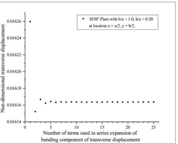
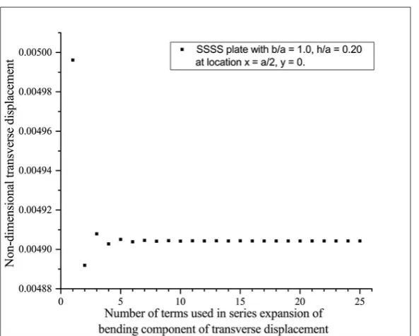
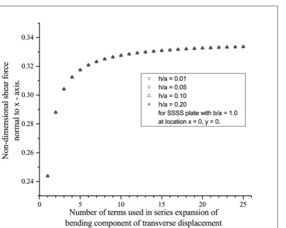
4. It should be noted that non-dimensional transverse displacement (w) at the center of the plate (x a / 2,y 0) predicted by the present theory (Table 3) for the case of square SFSF plate (Example 3) has good agreement with the corresponding results available in the literature (for square SFSF plate with h/a = 0.20, maximum percentage difference of 0.90 % is observed in predicting w by the present theory and by Mindlin plate theory (Lee et al. (2002)) with respect to the present theory). However, percentage difference of 4.58 % in predicting w by the present theory and by Mindlin plate theory (Lee et al. (2002)) with respect to the present theory is observed for square SFSF plate with h/a = 0.20 at location x a/ 2,y b/ 2. With regards to this case, following points should be noted:
Figure 3: Effect of number of terms in series expansion of bending component wb of transverse displacement w on non-dimensional transverse displacement w for the plate with SFSF boundary conditions (Example 3).
Hence, percentage difference of 4.58 % for square SFSF plate with h/a = 0.20 at location x a / 2, / 2
y b in predicting w by the present theory and by Mindlin plate theory (Lee et al. (2002)) with respect to the present theory is not due to lack of terms in series expansion of wb.
b. Even for the simple case of plate clamped edge boundary conditions, it is interesting to note as quoted by Groh and Weaver (2015), that “Essential boundary condition of vanishing Kirchoff rotation perpendicular to an edge (w,x 0 or w,y 0) is physically inaccurate, as the rotation at a clamped edge may in fact be non-zero due to the presence of transverse shear rotation.”
As mentioed earlier, this leads to inconsistencies with regards to the shear force arising in the formulation of flexural behaviour of plates with clamped edge boundary conditions using a certian class of axiomatic shear de-formation theories.
To the best of knowledge of authors, similar to the case of plate clamped edge boundary conditions, even plate free edge boundary conditions reported in the literature overall lack clarity in general.
c. Lee et al. (2002), Zenkour (2003), Thai and Choi (2013), Thai et al. (2013), Reddy et al. (2001), Salerno and Goldberg (1960) and Kant (1982) in which the work on flexural analysis of the plate with SFSF boundary conditions is reported, do not mention an exact solution for flexural analysis of the plate with SFSF boundary conditions obtained using three dimensional elasticity approach and authors are also unaware of such an exact solution for the plate with SFSF boundary conditions. Lack of such an exact solution restricts the comparison of the results obtained using the present theory with the corresponding results obtained using other shear deformation plate theories reported in the literature.
d. CPT requires specification of two bounary conditions per plate edge. It should be noted that for the case of plate free edge, one of the boundary conditions of CPT (Kirchoff shear force) is formulated using the combination of twisting moment along with shear force at that free edge (Timoshenko and Woinowsky-Krieger (1959), page no 83 through 88). Similar is the case with the present theory and it can be the possible reason behind percentage difference of 4.58 % for square SFSF plate with h/a = 0.20 at location
/ 2
x a ,y b/ 2 in predicting w. Hence, the result for above-mentioned case may not be as accurate as that obtained using other shear deformation plate theories reported in the literature.
However, it should also be noted that, as far as the plate with b/a = 1.0, h/a = 0.20 is concerned, it is possi-ble to debate on whether it qualifies as a plate or a stubby object. Percentage difference of 4.58 % for above-mentioned case needs to be construed by taking this point into account. The results for above-above-mentioned case are included in Table 3 due to availability of corresponding results in the literature. On the other hand, percentage difference in predicting w for square SFSF plate with h/a = 0.10 at location x a / 2,y b/ 2 is only 1.96 %.
SCSC, SCSS, SCSF and SSSF boundary conditions) obtained using the present theory have very good agreement with the corresponding results available in the literature.
15 CONCLUDING REMARKS
In this paper, single variable new first-order shear deformation theory for flexure of an isotropic plate is pre-sented. Important features of the present theory can be stated as follows:
1. The present theory is a displacement based first-order shear deformation plate theory and has single fourth-order partial governing differential equation involving only one unknown function. Whereas Mindlin plate theory, which is also a first-order shear deformation plate theory, involves three coupled partial governing differential equations and three unknown functions. 2. The displacement functions of the present theory give rise to constant transverse shear strains through the plate thickness. As is case of
Mindlin plate theory, the present theory also requires specification of a shear correction factor. 3. In the present theory, transverse shear stresses are obtained using modified constitutive relations.
4. By utilizing gross equilibrium equations, the governing differential equation of the present theory is obtained. The boundary conditions have been obtained based on physical understanding.
5. To the best of authors’ knowledge, the present theory is the only first-order shear deformation plate theory with two different types of physically meaningful clamped boundary conditions. Both clamped boundary conditions of the present theory are analogous to those discussed by Timoshenko and Goodier (1951) in the context of two-dimensional theory of elasticity approach for beam analysis. It is to be noted that the results obtained for plates with clamped edges using clamped edge: type 1 boundary condition of the present theory almost match with corresponding results available in the literature. In addition, the present theory specifies one more type of clamp boundary condition i.e. clamped edge: type 2, which has not been reported by any other first-order shear deformation plate theory available in the literature.
6. The expressions of the present theory have a striking resemblance to the corresponding expressions of classical plate theory in many aspects (e.g. governing differential equation, expressions for moments and shear forces). The only difference is that, bending
component wb (of transverse displacement w) appears in case of the present theory, whereas in case of classical plate theory, in its place transverse displacement w appears. Also, the expressions for shear forces obtained using the present theory are identical to those obtained using gross equilibrium equations.
7. Effectiveness of the present theory is demonstrated through illustrative examples for the plate flexure. The numerical results obtained are compared with corresponding results of other shear deformation plate theories available in the literature.
8. It is observed that, the efforts involved in obtaining solutions using the present theory are only marginally higher as compared to those involved in the case of classical plate theory.
In conclusion, the present plate theory is a simple and accurate first-order shear deformation plate theory for the flexure of isotropic plates.
16 DECLARATION OF CONFLICT OF INTEREST
The authors declare no potential conflicts of interest with respect to the research, authorship, and/or publi-cation of this article.
17 FUNDINGS
One of the author, Kedar S. Pakhare, would like to thank Indian Institute of Technology Bombay for the finan-cial support provided in the form of Master of Technology and Doctor of Philosophy stipend during the course of this work.
References
Cooke, D., Levinson, M. (1983). Thick rectangular plates-II: The generalized Lévy solution, International Journal of Mechanical Sciences 25: 207-215.
Ghugal, Y., Shimpi, R. (2002). A review of refined shear deformation theories of isotropic and anisotropic laminat-ed plates, Journal of Reinforclaminat-ed Plastics and Composites 21: 775-813.
Groh, R., Weaver, P. (2015). Static inconsistencies in certain axiomatic higher-order shear deformation theories for beams, plates and shells, Composite Structures 120: 231-245.
Lee, K., Lim, G., Wang, C. (2002). Thick Lévy plates re-visited, International Journal of Solids and Structures 39: 127-144.
Mindlin, R. (1951). Influence of rotary inertia and shear on flexural motions of isotropic, elastic plates, Journal of Applied Mechanics 18: 31-38.
Reddy, J., Wang, C., Lim, G., Ng, K. (2001). Bending solutions of Levinson beams and plates in terms of the classical theories, International Journal of Solids and Structures 38: 4701-4720.
Reissner, E. (1945). The effect of transverse shear deformation on the bending of elastic plates, Journal of Applied Mechanics 12: 69-77.
Salerno, V., Goldberg, M. (1960). Effect of shear deformations on the bending of rectangular plates, Journal of Ap-plied Mechanics 27: 54-58.
Senjanović, I., Vladimir, N., Tomić, M. (2013). An advanced theory of moderately thick plate vibrations, Journal of Sound and Vibration 332: 1868-1880.
Shimpi, R. (2002). Refined plate theory and its variants, AIAA Journal 40: 137-146.
Shimpi, R., Patel, H., Arya, H. (2007). New first-order shear deformation plate theories, Journal of Applied Mechan-ics 74: 523-533.
Shimpi, R., Shetty, R., Guha, A. (2017). A single variable refined theory for free vibrations of a plate using inertia related terms in displacements, European Journal of Mechanics A/Solids 65: 136-148.
Thai, H., Choi, D. (2013). Analytical solutions of refined plate theory for bending, buckling and vibration analyses of thick plates, Applied Mathematical Modelling 37: 8310-8323.
Thai, H., Park, M., Choi, D. (2013). A simple refined theory for bending, buckling, and vibration of thick plates rest-ing on elastic foundation, International Journal of Mechanical Sciences 73: 40-52.
Timoshenko, S., Goodier, J. (1951). Theory of Elasticity, McGraw-Hill Book Company, New York.
Timoshenko, S., Woinowsky-Krieger, S. (1959). Theory of Plates and Shells, McGraw-Hill Book Company, Singa-pore.