High-Speed Algorithm for Shielding Current Analysis in HTS Film
with Cracks
∗
)
Atsushi KAMITANI, Teruou TAKAYAMA, Ayumu SAITOH
1)and Hiroaki NAKAMURA
2)Yamagata University, 4-3-16 Johnan, Yonezawa, Yamagata 992-8510, Japan 1)University of Hyogo, 2167 Shosha, Himeji, Hyogo 671-2280, Japan
2)National Institute of Fusion Science, 322-6 Oroshi, Toki, Gifu 509-5292, Japan
(Received 23 November 2014/Accepted 17 February 2015)
A fast and stable method is proposed for calculating the time-varying shielding current density in a high-temperature superconducting (HTS) film containing cracks. If an initial-boundary-value problem of the shielding current density is formulated by theT-method, integral forms of Faraday’s law on crack surfaces are also im-posed as boundary conditions. As a result of the spatial discretization of the initial-boundary-value problem, semi-explicit differential algebraic equations (DAEs) are obtained. Although the DAEs can be solved with stan-dard ordinary-differential-equation (ODE) solvers, much CPU time is required for their numerical solution. In order to shorten the CPU time, the following high-speed algorithm is proposed: the blockLU decomposition is incorporated into function evaluations in ODE solvers. A numerical code is developed on the basis of the proposed algorithm and detectability of cracks by the scanning permanent-magnet method is numerically inves-tigated. The results of computations show that, when multiple cracks is contained in an HTS film, resolution of the scanning permanent-magnet method will be degraded remarkably.
c
⃝2015 The Japan Society of Plasma Science and Nuclear Fusion Research
Keywords: blockLUdecomposition, critical current density, high-temperature superconductor, integrodiff eren-tial equation, surface crack
DOI: 10.1585/pfr.10.3405023
1. Introduction
Recently, a high-temperature superconductor (HTS) has been used for numerous engineering applications: magnet, energy storage system, power cable and magnetic shielding apparatus. Since the evaluation of the shield-ing current density is indispensable for the design of en-gineering applications, several numerical methods [1–3] have been so far proposed to calculate the shielding cur-rent density.
After discretized with the implicit scheme and the finite element method (FEM), an initial-boundary-value problem of the shielding current density is transformed to a problem in which nonlinear algebraic equations have to be solved at each time step. Although this method can be also applied to the shielding current analysis in an HTS film containing cracks [3, 4], it is extremely time-consuming. Such time consumption is caused by a linear term with a dense matrix in the nonlinear equations. This method is called a conventional method, hereafter.
The authors proposed a high-speed method [2] for cal-culating the shielding current density in an HTS film. After discretized with the FEM, the initial-boundary-value prob-lem reduces to a system of first-order ordinary diff eren-tial equations (ODEs) that has a strong nonlinearity.
How-author’s e-mail: kamitani@yz.yamagata-u.ac.jp
∗)This article is based on the presentation at the 24th International Toki Conference (ITC24).
ever, the system cannot be always solved by means of an ODE solver even when an adaptive step-size control algo-rithm [5] is incorporated to the solver. In order to suppress an overflow in the algorithm, theJ-Econstitutive relation is slightly modified so that its solution may satisfy the orig-inal constitutive relation. As a result, the proposed method has a much higher speed than the conventional one. How-ever, the method is not applicable to the case where cracks are contained in an HTS film. This is mainly because the spatial discretization of the initial-boundary-value problem yields differential algebraic equations (DAEs) for this case. The purpose of the present study is to develop a fast and stable method for analyzing the shielding current den-sity in an HTS film containing cracks and to numerically investigate the scanning permanent-magnet method (SPM) [6] by means of the method.
2. Governing Equations
We first assume that an HTS film has the same cross sectionΩover the thickness and that it is exposed to the time-varying magnetic fieldB/µ0. By taking its thickness direction asz-axis and choosing its centroid as the origin, we use the Cartesian coordinate system ⟨O : ex,ey,ez⟩.
Furthermore, the HTS film is assumed to contain cracks whose cross sections are curved segments in thexyplane. Note that the boundary ∂Ω of Ω is composed of not only the outer boundaryC0 but also the inner boundaries
c
⃝2015 The Japan Society of Plasma
Fig. 1 An HTS film containing cracks.
C1,C2,· · ·,Cm. Apparently,C1,C2,· · ·,Cmdenote crack
surfaces (see Fig. 1). In the following,xandx′denote po-sition vectors of two points in thexyplane, whereas tand
nare a unit tangent vector and a unit normal vector on∂Ω, respectively. In addition,bdenotes a thickness of the HTS film.
In HTS films, the electric field E and the shielding current density jare closely related to each other through theJ-E constitutive relation. As the relation, we assume the following power law [2–4, 7, 8]:
E=E(|j|) j
|j|, E(j)=EC
(
j jC
)N
,
where jC and EC denote the critical current density and the critical electric field, respectively, andN is a positive constant.
Under the thin-plate approximation, there exists a scalar functionT(x,t) such that j = (2/b)∇ ×(Tez) and
its time evolution is governed by the following integrodif-ferential equation [1–4]:
µ0∂t( ˆWT)=−ez·(∇ ×E)−∂t⟨B·ez⟩. (1)
Here,⟨ ⟩denotes an average operator over the thickness and ˆWis the operator defined by
ˆ
WT ≡2T(x,t)
b +
"
ΩQ(|x−x
′|)T(x′,t) d2
x′,
whereQ(r)= −(πb2)−1[r−1−(r2+b2)−1/2]. Incidentally, (1) is derived from Faraday’s law. In other words, (1) is equivalent to Faraday’s law under the thin-plate approxi-mation.
The initial and boundary conditions to (1) are assumed as follows:
T =0 at t=0, (2)
T ∈H( ¯Ω), (3)
hi(E)≡ I
Ci
E·tds=0 (i=1,2,· · ·,m). (4) Here,H( ¯Ω) is a function space defined byH( ¯Ω)≡ {w(x) : w=0 on C0, ∂w/∂s=0 on C1,C2,· · ·,Cm},andsis an arclength along crack surfacesC1,C2,· · ·,Cm. Equation
(3) is based on j·n=0 onC0,C1,· · ·,Cm. In contrast, (4)
is integral forms of Faraday’s law on crack surfaces and it assures uniqueness of the initial-boundary-value problem of (1).
By solving (1) together with the initial and boundary conditions, we can investigate the time evolution ofT(x,t). OnceT(x,t) is determined at a certain time, the shielding current density at the same time can be easily evaluated by using j=(2/b)∇ ×(Tez).
3. Numerical Methods
For the purpose of solving the initial-boundary-value problem of (1), the authors developed the virtual voltage method [3]. However, it costs much CPU time. In order to resolve this difficulty, a new method is proposed. In this section, the proposed method is explained in detail and its speed is compared with that of the virtual voltage method. After spatially discretized with the FEM, the initial-boundary-value problem of (1) is transformed to the fol-lowing semi-explicit DAEs:
[
W11 W12]dT
dt = f1(t,T), (5)
g(T)=0, (6)
whereT ∈ Rn is a nodal vector originating fromT(x,t) and f1(t,T) ∈ Rn−mis a vector calculated from the
right-hand side of (1). Here,ndenotes a total number of nodes and it is assumed to satisfyn ≫m. In addition,W11 and W12 are an (n−m)×(n−m) matrix and an (n−m)×m matrix, respectively, and they correspond to the operator
ˆ
W. Furthermore, (6) is a discretized form of (4) and, hence,
g(T) is anm-dimensional vector. Note that (5) is derived from (1) and (3). Thus, (5) also contains the boundary condition (3).
Since (5) and (6) show the index-1 property, they can be rewritten as the following ODEs:
dT
dt = f(t,T), (7)
wheref(t,T)∈Rnis defined by
W(T)f(t,T)= f∗(t,T). (8) Here,W(T) and f∗(t,T) are given by
W(T)=
[
W11 W12 W21(T) W22(T)
]
, (9)
f∗(t,T)=
[
f1(t,T) 0
]
. (10)
In addition,W21(T) andW22(T) are anm×(n−m) matrix and anm×mmatrix, respectively, and they are given by
[
W12(T) W22(T)
]
In the 5th-order Runge-Kutta method, 6 evaluations of f(t,T) are needed at each time step. In other words, 6 linear systems such as (8) have to be solved for f(t,T) at each time step. As is apparent from the definition ofW(T), the submatrices,W11 andW12, ofW(T) do not depend on
T. Hence, high-speed solution of the linear system (8) can be realized by using the blockLUdecomposition ofW(T). SupposeW(T) can be written as a product of two ma-trices,
W(T)=
[
L11 O
L21(T) L22(T)
] [
U11 U12 O U22(T)
]
≡L(T)U(T). (11)
Here,L11,L22(T) andL(T) are lower triangular matrices whereasU11,U22(T) andU(T) are upper triangular matri-ces. In addition,L21(T) andU12are anm×(n−m) matrix and an (n−m)×mmatrix, respectively. By substituting (9) into (11), we get
W11=L11U11, (12)
W12=L11U12, (13)
W21(T)=L21(T)U11, (14) W22(T)−L21(T)U12 =L22(T)U22(T). (15) Thus, the block LU decomposition of W(T) can be achieved by using the following four steps:
1. A submatrixW11 isLU decomposed to get L11 and U11.
2. Equation (13) is solved forU12. 3. Equation (14) is solved forL21(T).
4. Anm×mmatrixW22(T)−L21(T)U12isLU decom-posed to getL22(T) andU22(T).
Note that, even if the nodal vectorTis unknown, both step 1 and step 2 are executable. In contrast, it is not untilT
is evaluated that both step 3 and step 4 can be carried out. In other words, step 1 and step 2 have to be only once ex-ecuted before the numerical solution of (7) is started. On the other hand, the remaining two steps must be performed at every evaluation off(t,T).
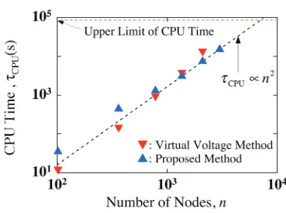
Once theLUdecomposition (11) ofW(T) is obtained, we can easily solve the linear system (8). Specifically, L(T)f†(t,T) = f∗(t,T) is first solved for f†(t,T) and U(T)f(t,T) = f†(t,T) is subsequently solved for f(t,T). Thus, not only step 3 and step 4 but also the numerical solutions of two linear systems are needed for each evalua-tion of f(t,T). Therefore, if we have already obtainedL11, U11andU12,O((m+2)n2) operations are required for cal-culating f(t,T). This means that onlyO((m+2)n2) opera-tions are needed at each time step of the proposed method. In contrast, O(n3) operations are necessary at each time step of the virtual voltage method. Therefore, the proposed method is expected to have a much higher speed than the virtual voltage method.
Let us compare the speed of the proposed method with that of the virtual voltage method. To this end, the
Fig. 2 The CPU timeτCPUas functions of the numbernof nodes for the case withm=1. Here,τCPUis measured for the simulation of the SPM in which values of parameters in Section 4.1 are used.
CPU timesτCPU required for both methods are measured on HITACHI SR16000/XM1 POWER7 of LHD Numeri-cal Analysis Server in National Institute of Fusion Science. The dependence of the CPU time on the number of nodes is depicted in Fig. 2. As expected, the proposed method is faster than the virtual voltage method for the case with n≳103. Especially, for the case withn=3007, the execu-tion of the virtual voltage method was forced to be termi-nated because the CPU time had exceeded the upper limit, 8.64×10⁴s. Hence, for this case, the proposed method is over 5.3 times faster than the virtual voltage method. From these results, we can conclude that the proposed method could be effective especially for a large-sized shielding cur-rent analysis in an HTS film containing cracks.
4. Application to SPM
By using the method explained above, a high-speed numerical code has been developed for analyzing the time evolution of j. A typical j-distribution is shown in Fig. 3. In this section, we numerically investigate detectability of cracks by the SPM.
4.1
Model of SPM
An HTS film is assumed to have a rectangular cross sectionΩ of lengthl and widthw, and cross sections of cracks are assumed to be line segments of lengthLc. In the following, the longitudinal direction ofΩis taken as x-axis.
In the SPM, a cylindrical permanent magnet of radius Rand heightHis moved along the film surface and, simul-taneously, an electromagnetic forceFzacting on the film is
Fig. 3 The j-distribution for the same case as B (a=20 mm) in Fig. 5. Here, the distribution is obtained at time satis-fyingxA =0 mm. In addition, the magnet movement is assumed asxA=x+(t). In this figure, thick line segments and green curves denote cracks and magnetic flux lines, respectively.
words, the HTS film is scanned with the permanent magnet in two opposite directions.
Throughout the present study, the physical and geo-metrical parameters are fixed as follows: R=0.8 mm, H =2 mm, L =0.5 mm, BF =0.1 T, jC =1.0 MA/cm2, EC =1 mV/m,N=20,b=1µm,l=32 mm,w=10 mm,Lc =2 mm,yA=0 mm, andv=10 cm/s. Here,BF/µ0 is the magnitude of the magnetic field at (x,y,z)=(xA,yA,b/2) for the case withv=0 cm/s.
4.2
Crack detection using SPM
As a measure of crack detection, we use the defect parameter [4] defined byd ≡sgn(∆Fz+·∆Fz−)|∆F+z·∆F−z|1/2. Here,∆Fz±denotes a change inFzdue to cracks forxA =
x±(t) (double-sign corresponds). Since∆Fz±depends only ontandxAis a monotonous function oft,∆Fz±becomes a function of xA. Hence, the defect parameterd can be treated as a function ofxA.
Let us first investigate how the defect parameter is in-fluenced by a single crack. The cross section of a crack is assumed to be a line segment connecting two points, (0 mm,±Lc/2), in thexyplane. The defect parameterdis calculated as a function ofxAand is depicted in Fig. 4. This figure indicates that the crack is contained in the shortest single intervalI(yA) such thatI(yA)⊇ {xA : |d(xA,yA)| ≥
α, |xA| ≤l/2}. Here,αis an infinitesimal positive constant. As is apparent from Fig. 4, ad-xAcurve is characterized by resolutionρ≡ |I(yA)|. Ifαis assumed asα=2×10⁻²mN, we getρ5.9 mm.
Next, we numerically investigate whether or not two cracks can be distinguished by the SPM. For this purpose, cross sections of two cracks are assumed to be the follow-ing two line segments in thexyplane: a line segment con-necting two points, (−a/2,±Lc/2), and a line segment con-necting two points, (a/2,±Lc/2). Here,a is the distance between two cracks. As explained above, resolutionρof single-crack detection is about 5.9 mm. Hence, if the in-equalitya ≳5.9 mm is satisfied, two cracks are expected to be separately detected by the SPM.
Dependences of the defect parameterdonxAare nu-merically determined fora =10 mm and fora=20 mm, and they are depicted in Fig. 5. Contrary to expectations, the inequality|d| < αis not satisfied even atxA=0 mm
Fig. 4 Dependence of the defect parameterd on the scanning positionxA. Resolutionρis also shown in this figure.
Fig. 5 Dependences of the defect parameterdon the scanning positionxA. Here, A:a=10 mm and B:a=20 mm.
for the case witha=10 mm. In contrast, it is fulfilled there for the case witha=20 mm. In other words, two cracks are regarded as a single crack for the case witha=10 mm, whereas they are completely distinguishable for the case witha=20 mm. This result implies that multiple cracks will remarkably affect resolution of the SPM.
5. Conclusion
SPM has been numerically investigated. Conclusions ob-tained in the present study are summarized as follows.
• The proposed method can be a powerful tool espe-cially for a large-sized shielding current analysis in an HTS film containing cracks.
• If an HTS film contains multiple cracks, resolution of the SPM might be degraded remarkably.
Acknowledgment
This work was supported in part by Japan Society for the Promotion of Science under a Grant-in-Aid for Scien-tific Research (C) (No. 24560321, No. 26520204). A part of this work was also carried out with the support and un-der the auspices of the NIFS Collaboration Research pro-gram (NIFS13KNTS025, NIFS13KNXN275).
[1] Y. Yoshida, M. Uesaka and K. Miya, IEEE. Trans. Magn. 30, 3503 (1994).
[2] A. Kamitani, T. Takayama and S. Ikuno, IEEE Trans. Magn.47, 1138 (2011).
[3] A. Kamitani, T. Takayama and S. Ikuno, IEEE Trans. Magn.49, 1877 (2013).
[4] A. Kamitani, T. Takayama, S. Ikuno and H. Nakamura, Plasma Fusion Res.9, 3405085 (2014).
[5] W.H. Press, S.A. Teukolsky, W.T. Vetterling and B.P. Flan-nery,Numerical Recipes in Fortran 77(Cambridge Univ. Press, New York, 1992) p.708.
[6] K. Hattori, A. Saito, Y. Takano, T. Suzuki, H. Yamada, T. Takayama, A. Kamitani and S. Ohshima, Physica C471, 1033 (2011).
[7] R. Brambilla, F. Grilli and L. Martini, IEEE Trans. Appl. Supercond.22, 8401006 (2012).