Numerical Solution for Circular Arc Cracks in Half Plane
Elasticity
N. R. F. Elfakhakhre 2, N. M. A. Nik long∗1, 2, Z. K. Eshkuvatov1, 3, and N. Senu1, 2 1Institute for Mathematical Research, Universiti Putra Malaysia, 43400 UPM Serdang,
Selangor, Malaysia
2Department of Mathematics, Faculty of Science, Universiti Putra Malaysia, 43400
UPM Serdang, Selangor, Malaysia
3Faculty of Science and Technology, Universiti Sains Islam Malaysia, 71800 Negeri
Sembilan, Malaysia
∗Corresponding author: [email protected]
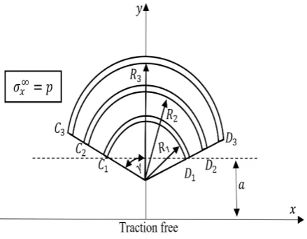
Numerical solutions for an elastic half plane with circular arc cracks subjected to uniaxial ten-sion σ∞x = p is presented. The free traction on the boundary of the half plane is assumed. Based on the modified complex potential and superposition method, the problem is formulated into a singular integral equation with the distribution dislocation function as unknown. Nu-merical examples exhibit the behavior of the stress intensity factor at the cracks tips for various positions. Our numerical results are in agreement with the existence one.
Keywords: stress intensity factor, singular integral equation, circular arc crack, half plane.
I.
Introduction
The influences between cracks is one of the main factors in determining the component life of structures since the interaction of the cracks can significantly affect the stress intensity fac-tors of the cracks. The stress intensity factor may increases or decreases. Due to this reason many researchers give a significant to develop the analytical methods to evaluate the stresses around multiple interacting cracks. Kachanov (2003) presented a short overview of several ap-proaches for two and three dimensional crack interaction problems. Li et al. (2008) proposed a fast and accurate solution for crack interac-tion problems in infinite and half plane. Based on the method of complex potentials, the fi-nal solution is obtained via a perturbation ap-proach.
A series of papers have been published to study the problem of three cracks as a special case of multiple cracks for several plane and different crack configurations. Three collinear, parallel, Griffith cracks problems are proposed
for dissimilar piezoelectric materials, infinite and orthotropic elastic plane by Lam and Phua (1991), Itou and Haliding (1997), Das and Pa-tra (1998), Das et al. (2001), Choi and Chung (2013), Itou (2016), Sadowski et al. (2016), and Akhtar and Hasan (2017). Chen and Hasebe (1997) and Yan (2010) proposed three circular arc cracks problem in an infinite plate by using Fredholm integral equation and boundary ele-ment method, respectively. Moreover, Bagheri (2017) determined the dynamic field stress in-tensity factors for three horizontal cracks by us-ing the numerical Laplace inversion and dislo-cation densities. In addition Elfakhakhre et al. (2018) solved the interaction of two curved cracks problem in half plane elasticity.
dislocation function as unknown. In the for-mulation, we make use the modified complex potential. The appropriate quadrature formu-las together with a suitable choice of colloca-tion points, the singular integral equacolloca-tions are reduced to the system of linear equations for the unknown coefficients. Numerical examples exhibit the values of stress intensity factor are influenced by the distance between the cracks.
II.
The problem formulation
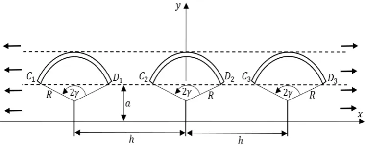
Assume that three circular arc cracks lie on the upper half plane with the same radius R sub-jected to uniaxial tension σx∞ = p as shown in Figure 1. To solve this problem, Muskhel-ishvili’s method for plane elasticity is utilized (Muskhelishvili (1953)). Based on this method, the stresses (σx, σy, σxy), the resultant forces
(X, Y) and the displacements (u, v) can be de-scribed used two complex potentials Φ(z) =
φ0(z) and Ψ(z) =ψ0(z) as
σx+σy = 4Re[Φ(z)], (1)
σy−iσxy = 2ReΦ(z) +zΦ
0
(z) + Ψ(z), (2)
f =−Y +iX =φ(z) +zφ0(z) +ψ(z), (3)
2G(u+iv) =κφ(z)−zφ0(z)−ψ(z), (4)
where G is shear modulus of elasticity, κ = (3− v)/(1 +v) in the plane stress problem,
κ = 3−4v in the plane strain problem, v is the Poisson’s ratio, and a bar over a function denotes the conjugated value for the function. The derivative in a specified direction (abbre-viated as DISD) is defined as
N+iT = d
dz(−Y +iX)
= Φ(z) + Φ(z) + dz¯
dz
zΦ0(z) + Ψ(z),
(5)
whereN+iT denotes the normal and tangen-tial tractions along the crack segmentz, z+dz. The value of N +iT depends on the positions of point z as well as on the direction of the segment dz/dz¯ .
The problem is formulated as a spe-cial case for multiple curved cracks problem (Elfakhakhre et al. (2018)). By consider the distribution dislocation functionsg01(t1),g20(t2),
andg30(t3), respectively, for crack-1 (L1),
crack-2 (L2), and crack-3 (L3). LetNk(tk0)+iTk(tk0)
be the tractions applied on the crack-k at the point tk0 fork= 1,2,3, then the equations for
the three cracks subjected to traction can be written as follow
1
π −
Z
Lk
g0k(tk)dtk tk−tk0
+ 1 2π
Z
Lk
B1(tk, tk0)gk0(tk)dtk+
Z
Lk
B2(tk, tk0)g0k(tk)dtk¯ ! + 3 X j=1 0" 1 π Z Lj
g0j(tj)dtj
tj−tk0
+ 1 2π
Z
Lj
B1(tj, tk0)g0j(tj)dtj+
Z
Lj
B2(tj, tk0)gj0(tj)dtj¯
!#
=Nk(tk0) +iTk(tk0),
(6)
where the function g0(tk) is defined as
g0(tk) =− 2Gi
κ+ 1
d dtk
n
(u(tk) +iv(tk))+
−(u(tk) +iv(tk))−
o
,
(7)
wheretk∈Lk, the subscript (+) (or (-)) mean
the upper (or lower) face of each crack, and ((u(tk)+iv(tk))+−(u(tk)+iv(tk))−) represents
the displacements at a pointtkof the upper and
lower faces of each crack Lk. In Equation (7) the expression d{}/dt should be defined as in Muskhelishvili (1953) and Chen et al. (2003). In Equation (6) the kernels are expressed as follow
B1(tj, tk0) =A1(tj, tk0) +A3(tj, tk0) +A5(tj, tk0),
B2(tj, tk0) =A2(tj, tk0) +A4(tj, tk0) +A6(tj, tk0),
Figure 1: Three collinear circular arc cracks in an elastic half plane.
and
A1(tj, tk0) =−
1
tj−tk0
+ 1
tj−tk0
dtk0
dtk0
,
A2(tj, tk0) =
1
tj−tk0
− tj−tk0
(tj −tk0) 2
dtk0
dtk0
,
A3(tj, tk0) =−
1
tj−tk0
+ tj −tj (tj−tk0)2
,
A4(tj, tk0) =−
1
tj−tk0
+ tj −tj (tj−tk0)2
,
A5(tj, tk0) =
dtk0
dtk0
2tk0(tj −tj)
(tj−tk0)3
+
(3tk0−tj)
(tj−tk0)2
+2tk0(tk0−tj) (tj−tk0)3
!
,
A6(tj, tk0) =
dtk0
dtk0
tj−tk0
(tj−tk0)2
.
Note that in Equation (6) the symbol P0
de-notes the terms corresponding to j=k are ex-cluded, and the first three integrals represent to the effect on crack-k caused by the disloca-tions on the crack-k itself, whereas the other three integrals denote the effect of the disloca-tions on crack-jwherej = 1,2,3, j6=k. In ad-dition, the single-valuedness conditions of dis-placement dislocation functions gk0(tk) are de-fined as
Z
Lk
g0k(tk)dtk= 0, fork= 1,2,3. (8)
In solving Equation (6) subjected to Equa-tion (8), we map the cracks on a real axis by
sk with intervals of 2bk for crack-k,k= 1,2,3.
The mappings are expressed as (Chen (2004))
gk0(tk)|tk=tk(sk) =hk(sk) =
Hk(sk)
q
b2
k−s2k ,
where Hk(sk) =Hk1(sk) +iHk2(sk).
(9)
The following Gauss integration rules ( Erdo-gan et al. (1973)) are also used in solving the integral equations
1
π
Z b
−b
F(s)
√
b2−s2(s−s 0,m)
ds= 1
M M
X
i=1
F(si) (si−s0,m)
, (10) 1 π Z b −b
F(s)
√
b2−s2ds=
1
M M
X
i=1
F(si), (11)
whereM is some integer, and
si=bcos
(i−0.5)π
M ,
s0,m=bcos mπ
M ,
fori= 1,2, . . . , M, andm= 1,2, . . . , M −1.
III.
NUMERICAL
EXAMPLES
The stress intensity factor (SIF) at the crack tips C1 andD1 of crack-1,C2 andD2 of
crack-2, andC3 and D3 of crack-3 (Figure 1) can be
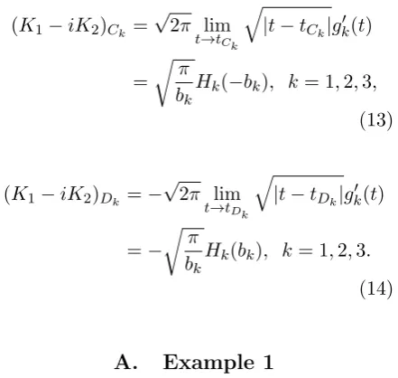
evaluated as follow (Chen (2004))
(K1−iK2)Ck =
√
2π lim
t→tCk
q
|t−tCk|gk0(t)
=
r
π bk
Hk(−bk), k= 1,2,3,
(13)
(K1−iK2)Dk =−
√
2π lim
t→tDk
q
|t−tDk|gk0(t)
=− r
π bk
Hk(bk), k= 1,2,3.
(14)
A. Example 1
Assume that three collinear circular arc cracks of angle 2γ lie in upper half plane as seen in Figure 1 with radiusRand free traction on the boundary. The cracks subjected to the remote tension σx∞ = p. The SIFs at the cracks tips are expressed as
K1Ck =F1Ck(a/R,2b/h)σ∞x
√
πb,
K2Ck =F2Ck(a/R,2b/h)σ∞x
√
πb,
K1Dk =F1Dk(a/R,2b/h)σ∞x
√
πb,
K2Dk =F2Dk(a/R,2b/h)σ∞x
√
πb,
whereb=Rsin (γ) for k= 1,2,3.
(15)
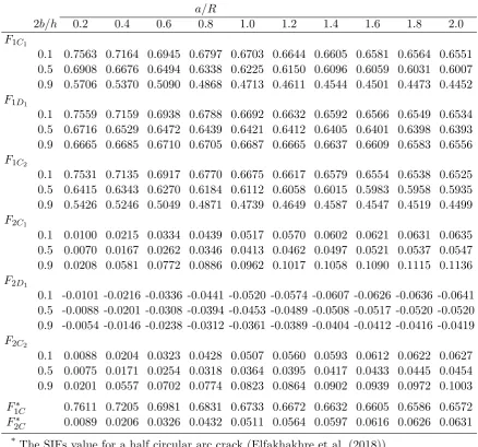
The calculated SIFs at the cracks tips C1,
D1, and C2 are listed in Table 1, which
illus-trates the variation of the SIFs with a/R = 0.2,0.4, . . . ,2.0 and the dimensionless distance 2b/h = 0.1,0.5,0.9 for γ = 90◦, where a is the distance between the cracks tips and the boundary of half plane. Note that, F1C1 = F1D3, F1D1 = F1C3, F1C2 = F1D2, F2C1 =
−F2D3, F2D1 = −F2C3, and F2C2 = −F2D2. In the case 2b/h = 0.1, the data in Table 1
are compared with those of Elfakhakhre et al. (2018) for a half circular arc crack, it is found to be in good agreement. It indicates that in the case 2b/h = 0.1 the interaction between three circular arc cracks is negligible, and our numerical results are reliable. Observed that the SIFs at crack tipsC1andC2decrease as the
2b/hincreases but atD1there is slightly
distur-bance. Whereas the SIFs increase as a/R de-creases. Figure 2 shows that the SIFs increases as the half opening crack angle (γ) increases for
a/R= 0.2 and 2b/h= 0.9.
B. Example 2
Assume that three collinear circular arc cracks of angle 2γ lie in upper half plane as seen in Figure 3 with the same radiusRand free trac-tion on the boundary. The cracks subjected to the remote tension σx∞ = p. The SIFs at the
Figure 2: Nondimensional SIFs for three cir-cular arc crack in an elastic half plane when
Table 1: Nondimensional SIFs for three circular arc cracks in an elastic half plane (Figure 1).
a/R
2b/h 0.2 0.4 0.6 0.8 1.0 1.2 1.4 1.6 1.8 2.0
F1C1
0.1 0.7563 0.7164 0.6945 0.6797 0.6703 0.6644 0.6605 0.6581 0.6564 0.6551 0.5 0.6908 0.6676 0.6494 0.6338 0.6225 0.6150 0.6096 0.6059 0.6031 0.6007 0.9 0.5706 0.5370 0.5090 0.4868 0.4713 0.4611 0.4544 0.4501 0.4473 0.4452
F1D1
0.1 0.7559 0.7159 0.6938 0.6788 0.6692 0.6632 0.6592 0.6566 0.6549 0.6534 0.5 0.6716 0.6529 0.6472 0.6439 0.6421 0.6412 0.6405 0.6401 0.6398 0.6393 0.9 0.6665 0.6685 0.6710 0.6705 0.6687 0.6665 0.6637 0.6609 0.6583 0.6556
F1C2
0.1 0.7531 0.7135 0.6917 0.6770 0.6675 0.6617 0.6579 0.6554 0.6538 0.6525 0.5 0.6415 0.6343 0.6270 0.6184 0.6112 0.6058 0.6015 0.5983 0.5958 0.5935 0.9 0.5426 0.5246 0.5049 0.4871 0.4739 0.4649 0.4587 0.4547 0.4519 0.4499
F2C1
0.1 0.0100 0.0215 0.0334 0.0439 0.0517 0.0570 0.0602 0.0621 0.0631 0.0635 0.5 0.0070 0.0167 0.0262 0.0346 0.0413 0.0462 0.0497 0.0521 0.0537 0.0547 0.9 0.0208 0.0581 0.0772 0.0886 0.0962 0.1017 0.1058 0.1090 0.1115 0.1136
F2D1
0.1 -0.0101 -0.0216 -0.0336 -0.0441 -0.0520 -0.0574 -0.0607 -0.0626 -0.0636 -0.0641 0.5 -0.0088 -0.0201 -0.0308 -0.0394 -0.0453 -0.0489 -0.0508 -0.0517 -0.0520 -0.0520 0.9 -0.0054 -0.0146 -0.0238 -0.0312 -0.0361 -0.0389 -0.0404 -0.0412 -0.0416 -0.0419
F2C2
0.1 0.0088 0.0204 0.0323 0.0428 0.0507 0.0560 0.0593 0.0612 0.0622 0.0627 0.5 0.0075 0.0171 0.0254 0.0318 0.0364 0.0395 0.0417 0.0433 0.0445 0.0454 0.9 0.0201 0.0557 0.0702 0.0774 0.0823 0.0864 0.0902 0.0939 0.0972 0.1003
F1∗C 0.7611 0.7205 0.6981 0.6831 0.6733 0.6672 0.6632 0.6605 0.6586 0.6572
F2∗C 0.0089 0.0206 0.0326 0.0432 0.0511 0.0564 0.0597 0.0616 0.0626 0.0631
*The SIFs value for a half circular arc crack (Elfakhakhre et al. (2018))
Table 2: Nondimensional SIFs at the crack tipsC1 andD1 for three circular arc cracks in
an elastic half plane (Figure 3).
γ(◦)
2b/h 15 30 45 60 75 90
F1C1
0.1 1.3586 1.0720 0.6662 0.2213 -0.1569 -0.1901 0.5 1.3275 0.9994 0.6057 0.2078 -0.1557 -0.1901 0.9 1.2750 0.9310 0.5515 0.1622 -0.1267 -0.1901
F1D1
0.1 1.0946 0.9078 0.6449 0.3524 0.0545 -0.0255 0.5 1.0676 0.8305 0.5325 0.2328 0.0163 -0.0255 0.9 1.0262 0.7703 0.4730 0.2068 -0.0533 -0.0255
F2C1
0.1 0.4008 0.7472 0.9373 0.9553 0.7744 0.2045 0.5 0.4032 0.6725 0.7867 0.7664 0.5999 0.2045 0.9 0.3769 0.6010 0.7258 0.7272 0.6096 0.2045
F2D1
0.1 -0.2675 -0.5092 -0.6544 -0.6999 -0.6334 -0.2023 0.5 -0.2787 -0.4992 -0.6222 -0.6106 -0.4583 -0.2023 0.9 -0.2847 -0.4994 -0.5890 -0.5591 -0.4076 -0.2023
cracks tips are expressed as
K1Ck =F1Ck(γ,2b/h)σ∞x
√
πb,
K2Ck =F2Ck(γ,2b/h)σ∞x
√
πb,
K1Dk =F1Dk(γ,2b/h)σ∞x
√
πb,
K2Dk =F2Dk(γ,2b/h)σ
∞
x
√
πb,
whereb=Rsin (γ) for k= 1,2,3.
(16)
The calculated SIFs at the cracks tips are given in Table 2, Table 3, and Table 4 in which illustrate the variation of the SIFs with
γ = 15◦,30◦,45◦,60◦,75◦,90◦ and dimension-less distance 2b/h = 0.1,0.5,0.9 for a = 0.2Rsin(γ), where a is defined as in Figure 3. In the case 2b/h = 0.1 and γ = 15◦, the data in Tables 2, 3, and 4 are compared with those of Chen et al. (2009) for an arc crack, and it is found that the agreement is very good. Note that, in the case of an arc crack in an infinite
plate we have
F1C(a/R)a/R=0.2 = 1.3609,
F2C(a/R)a/R=0.2 = 0.4154,
F1D(a/R)a/R=0.2 = 1.0953
F2D(a/R)a/R=0.2 =−0.2792.
It indicates that in the case 2b/h = 0.1 the interaction between three circular arc cracks is negligible, and our numerical results are re-liable. Note that the effect of interaction is nonexistent between the cracks when γ = 90◦.
C. Example 3
Consider three circular arc cracks of angle 2γlie in upper half plane (Figure 4) with the radius
R1,R2, andR3, andR1/R2=R2/R3=λ. The
cracks subjected to the remote tensionσ∞x =p
Table 3: Nondimensional SIFs at the crack tipsC2 andD2 for three circular arc cracks in
an elastic half plane (Figure 3).
γ(◦)
2b/h 15 30 45 60 75 90
F1C2
0.1 1.3582 1.0684 0.6592 0.2084 -0.1843 -0.1901 0.5 1.3058 0.9348 0.5240 0.1939 0.0409 -0.1901 0.9 1.2750 0.9310 0.5515 0.1622 -0.1267 -0.1901
F1D2
0.1 1.0937 0.9055 0.6419 0.3553 0.0964 -0.0255 0.5 1.0546 0.8206 0.5633 0.3125 0.1288 -0.0255 0.9 1.0021 0.7786 0.5224 0.2921 0.0617 -0.0255
F2C2
0.1 0.4146 0.7445 0.9301 0.9353 0.7220 0.2045 0.5 0.3987 0.6545 0.7506 0.7289 0.5884 0.2045 0.9 0.3726 0.5854 0.6880 0.6790 0.5063 0.2045
F2D2
0.1 -0.2787 -0.5067 -0.6482 -0.6855 -0.6157 -0.2023 0.5 -0.2690 -0.4638 -0.5722 -0.5456 -0.3889 -0.2023 0.9 -0.2569 -0.4375 -0.4967 -0.4484 -0.3414 -0.2023
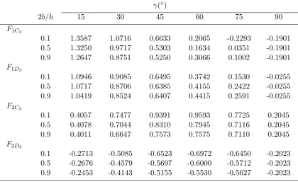
Table 4: Nondimensional SIFs at the crack tipsC3 andD3 for three circular arc cracks in
an elastic half plane (Figure 3).
γ(◦)
2b/h 15 30 45 60 75 90
F1C3
0.1 1.3587 1.0716 0.6633 0.2065 -0.2293 -0.1901 0.5 1.3250 0.9717 0.5303 0.1634 0.0351 -0.1901 0.9 1.2647 0.8751 0.5250 0.3066 0.1002 -0.1901
F1D3
0.1 1.0946 0.9085 0.6495 0.3742 0.1530 -0.0255 0.5 1.0717 0.8706 0.6385 0.4155 0.2422 -0.0255 0.9 1.0419 0.8524 0.6407 0.4415 0.2591 -0.0255
F2C3
0.1 0.4057 0.7477 0.9391 0.9593 0.7725 0.2045 0.5 0.4078 0.7044 0.8310 0.7945 0.7116 0.2045 0.9 0.4011 0.6647 0.7573 0.7575 0.7110 0.2045
F2D3
Table 5: Nondimensional SIFs for three circular arc cracks with different radius in an elastic half plane (Figure 4).
λ
γ(◦) 0.1 0.2 0.3 0.4 0.5 0.6 0.7 0 .8 0.9
F1C1 30 0.0262 0.0212 0.0204 0.0244 0.0339 0.0506 0.0758 0.1036 0.1394 60 0.2276 0.2313 0.2453 0.2634 0.2798 0.2909 0.2990 0.3095 0.3126 90 0.5545 0.5533 0.5585 0.5654 0.5648 0.5520 0.5319 0.5195 0.5154
F1C2
30 0.0697 0.0653 0.0619 0.0592 0.0578 0.0610 0.0734 0.0944 -0.0751 60 0.3564 0.3503 0.3465 0.3385 0.3265 0.3132 0.3020 0.2926 0.2587 90 0.6623 0.6422 0.6195 0.5884 0.5508 0.5137 0.4857 0.4643 0.4136
F1C3
30 0.1940 0.1930 0.1906 0.1858 0.1769 0.1621 0.1431 0.1299 0.1841 60 0.5138 0.5103 0.5041 0.4944 0.4799 0.4576 0.4234 0.3789 0.3622 90 0.7572 0.7468 0.7308 0.7098 0.6838 0.6510 0.6074 0.5503 0.5026
F2C1
30 0.1302 0.1366 0.1465 0.1582 0.1717 0.1849 0.1904 0.1780 0.1461 60 0.2285 0.2175 0.2014 0.1865 0.1743 0.1668 0.1668 0.1747 0.1764 90 0.1134 0.1002 0.0742 0.0492 0.0286 0.0173 0.0167 0.0294 0.0596
F2C2
30 0.1552 0.1618 0.1725 0.1854 0.1979 0.2052 0.1982 0.1703 0.1518 60 0.2104 0.1951 0.1827 0.1736 0.1682 0.1677 0.1713 0.1662 0.1374 90 0.0526 0.0411 0.0280 0.0190 0.0136 0.0124 0.0164 0.0219 0.0127
F2C3
30 0.2360 0.2352 0.2334 0.2301 0.2240 0.2138 0.1993 0.1842 0.2120 60 0.2262 0.2245 0.2219 0.2184 0.2137 0.2071 0.1969 0.1787 0.1520 90 0.0089 0.0090 0.0095 0.0105 0.0124 0.0150 0.0168 0.0097 -0.0276
K1Ck =F1Ck(γ, λ)σx∞
√
πb,
K2Ck =F2Ck(γ, λ)σ
∞
x
√
πb,
K1Dk =F1Dk(γ, λ)σ
∞
x
√
πb,
K2Dk =F2Dk(γ, λ)σx∞
√
πb,
whereb=Rsin (γ) for k= 1,2,3.
(17)
The calculated SIFs at the cracks tips are given in Table 5, which illustrates the varia-tion of the SIFs with γ = 30◦,60◦,90◦ and
λ= 0.1,0.2, . . . ,0.9 for a= 0.2, where ais de-fined as in Figure 4. Observed that at the crack tip C3 forλ= 0.1 andγ = 90◦ the data in
Ta-ble 5 are compared with those of Elfakhakhre
et al. (2018) for a half circular arc crack (see Ta-ble 1), and it is found to be in good agreement. It indicates that in the case λ= 0.1 the inter-action between three circular arc cracks is neg-ligible, and our numerical results are reliable. Note that the SIFs increase as γ increases.
IV.
CONCLUSION
Figure 4: Three circular arc cracks in upper elastic half plane with different radius.
numerical purpose we apply the curve coordi-nate method and appropriate quadrature rules. The several numerical results exhibit the effec-tiveness of this approach and also illustrate the effect of the cracked geometry on the stress in-tensity factor. We can conclude that the stress intensity factor is influenced by the distance between cracks, distance between cracks and boundary, and the position and configurations of the cracks.
ACKNOWLEDGEMENTS
The author would like to thank University Pu-tra Malaysia for the PuPu-tra Grant, Vot No. 9567900.
References
[1] N. Akhtar and S. Hasan. Assessment of the interaction between three collinear unequal straight cracks with unified yield zones. AIMS Materials Science, 4:302– 316, 2017.
[2] R. Bagheri. Several horizontal cracks in a piezoelectric half-plane under transient loading. Archive of Applied Mechanics, 87:1979–1992, 2017.
[3] Y. Z. Chen. Solution of integral equation in curve crack problem by using curve length coordinate. Engineering Analysis Boundary Elements, 28:989–994, 2004.
[4] Y. Z. Chen and N. Hasebe. Fredholm integral equation for the multiple circu-lar arc crack problem in plane elastic-ity. Archive of Applied Mechanics, 67: 433–446, 1997.
[5] Y. Z. Chen, N. Hasebe, and K. Y. Lee. Multiple Crack Problems in Elasticity. WIT Press, Southampton, 2003.
[6] Y. Z. Chen, X. Y. Lin, and X. Z. Wang. Numerical solution for curved crack prob-lem in elastic half-plane using hypersin-gular integral equation. Philosophical Magazine, 89(26):2239–2253, 2009.
[7] S. R. Choi and I. Chung. Analysis of three collinear antiplane interfacial cracks in dissimilar piezoelectric materi-als under non-self equilibrated electrome-chanical loadings on a center crack. Jour-nal of Mechanical Science and Technol-ogy, 27:3097–3101, 2013.
[8] S. Das and B. Patra. Interaction be-tween three line cracks in a sandwiched orthotropic layer.Applied Mechanics and Engineering, 3(2):249–269, 1998.
[9] S. Das, B. Patra, and L. Debnath. In-teraction between three moving Griffith cracks at the interface of two dissimilar elastic media.Korean Journal of Compu-tational and Applied Mathematics, 8(1): 59–69, 2001.
[10] N. R. F. Elfakhakhre, N. M. A. Nik Long, and Z. K. Eshkuvatov. Stress intensity factor for an elastic half plane weakened by multiple curved cracks.Applied Math-ematical Modelling, 60:540–551, 2018.
equation. In G. C. Sih, editor, Mechan-ics of Fracture, pages 368–425. Leyden Noordhoff, 1973.
[12] S. Itou. Dynamic stress intensity factors of three collinear cracks in an orthotropic plate subjected to time-harmonic distur-bance. Journal of Mechanics, 32:491– 499, 2016.
[13] S. Itou and H. Haliding. Dynamic stress intensity factors around three cracks in an infinite elastic plane subjected to time-harmonic stress waves . Interna-tional Journal of Fracture, 83:379–391, 1997.
[14] M. Kachanov. On the problems of crack interactions and crack coalescence. In-ternational Journal of Fracture, 120:537– 543, 2003.
[15] K. Y. Lam and S. P. Phua. Multiple crack interaction and its effect on stress inten-sity factor. Engineering Fracture Me-chanics, 40:585–592, 1991.
[16] D. F. Li, C. F. Li, S. Q. Shu, Z. X. Wang, and J. Lu. A fast and accurate analysis of the interacting cracks in linear elastic solids. International Journal of Fracture, 151:169–185, 2008.
[17] N. I. Muskhelishvili. Some Basic Prob-lems of Mathematical Theory of Elastic-ity. Noordhoff International Publishing, Leyden, The Netherlands, 1953.
[18] T. Sadowski, E. M. Craciun, A. Rabaea, and L. Marsavina. Mathematical model-ing of three equal collinear cracks in an orthotropic solid.Meccanica, 51:329–339, 2016.