High Performance Iterative Solver for Linear System
using Multi GPU
∗
)
Soichiro IKUNO
1), Norihisa FUJITA
1), Yuki KAWAGUCHI
1), Taku ITOH
2), Susumu NAKATA
3),
Kota WATANABE
4)and Hiroyuki NAKAMURA
5)1)Tokyo University of Technology, 1404-1 Katakura, Hachioji, Tokyo 192-0982, Japan 2)Seikei University, 3-3-1 Kichijoji-kitamachi, Musashino, Tokyo 180-8633, Japan
3)Ritsumeikan University, 1-1-1 Nojihigashi, Kusatsu, Shiga 525-5062, Japan 4)Hokkaido University, 14-9 Kita-ku, Sapporo 060-0814, Japan
5)National Institute for Fusion Science, 322-6 Oroshi-cho, Toki, Gifu 509-5292, Japan
(Received 22 December 2010/Accepted 28 March 2011)
The variable preconditioned (VP) Krylov subspace method on multi Graphics Processing Unit (GPU) is numerically investigated. Besides, the linear system obtained by finite element method with an edge element is adopted for the problem. The results of computations show that VP conjugate gradient method on multi GPU demonstrated significant achievement than that of CPU. Especially, VP conjugate gradient method on multi GPU is 4.35 times faster than that of CPU. However, transmission rate between the PC using Gigabit Ethernet is the bottleneck of the performance.
c
2011 The Japan Society of Plasma Science and Nuclear Fusion Research
Keywords: variable preconditioned Krylov subspace method, GPGPU, CUDA, singular matrix, edge element DOI: 10.1585/pfr.6.2401069
1. Introduction
As is well known that an initial and boundary value problem of partial differential equation is obtained from formulating a physical and engineering phenomena of plasma such as equilibrium configurations of Spheromak plasma or Tokamak plasma [1]. And discredizing the prob-lem, large scale linear system is appeared and it takes much time to solve the system. Thus, it is necessary to reduce the computation time of solving a system for real time simu-lation or high resolution simusimu-lation. One of the solution is using Graphic Processing Unit.
The Graphics Processing Unit (GPU) is one of the most progressive device and it performs about 20 or 70 times faster than CPU. As the result, various researches of General Purpose computing on GPU (GPGPU) have been proposed aggressively [2, 3]. Though GPU has a high per-formance computation power, it is very difficult to program on GPU because the architecture of GPU or graphics API must be used for programming.
K. Abeet al. developed new preconditioning strategy which is called the Variable Preconditioned Generalized Conjugate Residual (VPGCR) method [4]. In VPGCR, the residual equation is solved in each iteration instead of pre-conditioned matrix calculation. Variable Prepre-conditioned (VP) Krylov subspace method is constituted by addition of vectors, inner products and multiplication of matrices, and vectors. These operations are very easy to parallelize author’s e-mail: [email protected]
∗)This article is based on the presentation at the 20th International Toki
Conference (ITC20).
and tuning. Thus, VP Krylov subspace method is one of the settlements of GPGPU.
The purpose of the present study is to evaluate numer-ically the performance of VP Krylov subspace method and to implement VP Krylov subspace method on multi GPU using Message Passing Interface.
2. GPU and CUDA
In recent years, commodity Graphics Processing Units (GPUs) have been obtained large computation power since applications like 3D games needs a realistic visualization. Furthermore, GPU architectures have been changed from fixed operation to flexible organization for programmabil-ity; therefore, GPUs are capable of scientific computing more than the specific graphics operation. For example, GeForce GTX 480 can perform up to 1.35 TFLOPS by using single precision and 672 GFLOPS by using double precision. This performance is about a performance of 13 times of Core i7 930 by using double precision. How-ever, computations on GPU are restricted to single pre-cision floating point arithmetics, and rounding operation is fixed to truncate. Although a double precision floating point value can be emulated with two single precision val-ues, long execution time is needed.
There are some difficult points in operations using GPU, and these difficulties are shown as follows.
• It is necessary to achieve interdependence with data processing in the back and forth because GPU spe-cializes in the parallel processing in the input data
op-c
2011 The Japan Society of Plasma
eration.
• The communication speed between threads and main memory or VRAM is very slow.
• If shared memory, texture memory and constant memory are not used the performance of GPU can-not be drawn out.
Compute Unified Device Architecture (CUDA) is ar-chitecture with new hardware and the software to manage the calculation on GPU as a parallel computer developed by the NVIDIA corporation [5]. In addition, when CUDA is used, we do not have to move the data to graphics API. The concept related to the graphics like the texture mem-ory and the frame buffer, etc. did not worry when CUDA is used, and it is possible to treat comparatively with the operation in CPU. CUDA can run on the Geforce 8 series or later.
3. Variable
Preconditioned
Krylov
Subspace Method
As known well, a preconditioning strategy can im-prove the performance for solving a linear systemAx=b using the Krylov subspace method. Here, A,xandb de-note a coefficient matrix, an unknown vector and a known vector, respectively. Generally, a preconditioned matrixM is determined by incomplete LU decomposition, and a vec-torM−1rkis calculated atk-th iteration by using backward
substitution or incomplete Cholesky factorization. Here, rk denotes residual vector at k-th iteration. The
calcula-tion time of solving linear system is relatively large for the preconditioned part.
K. Abeet al.developed new preconditioning strategy which is called the variable preconditioning method [4]. In Ref. [4], Variable Preconditioned (VP) Generalized Con-jugate Residual (GCR) method is proposed. VPGCR has two nested iterations for GCR and variable precondition-ing for GCR are called as outer-loop and inner-loop, re-spectively. In VPGCR, the residual equations Az0 = r0
andAzk+1 =rk+1are solved in each outer-loop and
inner-loop instead of preconditioned matrix calculation. Here, subscript denotes an iteration number. Naturally, VPGCR takes much CPU time than that of general GCR method if the residual equation is solved in high accuracy. How-ever, VPGCR has the advantageous character. The con-vergence theorem of VPGCR is guaranteed that the resid-ual of VPGCR converges if the relative residresid-ual norm of inner-loop satisfies the following condition.
rin=||r
k+1−Azk+1||2
||rk+1||2 <1.
(1) Here,||x||2denotes 2-norm of vectorx. That is to say; the
residual equation can be solved roughly by using iterative method with only a few iteration. Generally, a stationary iterative method such as Gauss-Seidel method, is adopted for variable preconditioning procedure, and SOR method is adopted for inner-loop in Ref. [4].
begin procedureVP Conjugate Gradient
x0←Set a initial value.
begin loop r0←b−Ax0
z0← roughly solveAz0=r0
p0←z0
begin fork←1,2,· · ·,m
αk← (rk,zk) (pk,Apk)
xk+1←xk+αkpk
rk+1←rk−αkApk
zk+1← roughly solveAzk+1=rk+1 βk←
(rk+1,zk+1)
(rk,zk)
pk+1←zk+1+βkpk
qk+1←Azk+1+ k
i=0 βk,iqi
end for x0←xk
end loop end procedure
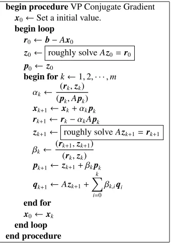
Fig. 1 The algorithm of Variable Preconditioned Conjugate Gra-dient (VPCG) method.
VP Krylov subspace method is developed based on preconditioned Krylov subspace method. Therefore, VP Krylov subspace method can be developed by replacing the preconditioning procedure (i.e. incomplete LU decomposi-tion) for which preconditioned Krylov subspace methods is used with iterative solvers. For this reason, VP Krylov sub-space method can be easily extended by using other Krylov subspace method according to the target problem. In the present study, a symmetric coefficient matrix is adopted for numerical experiments. Thus, instead of GCR method, CG method is adopted for outer-loop. Here, we show the algorithm of VPCG in Fig. 1.
4. Linear System Obtained by FEM
with Edge Element
In this study, the Problem 20 in Testing Electromag-netic Analysis Methods (T.E.A.M.) Workshop is employed for the benchmark [6]. The analytic region is divided into four symmetric region, and a piece of the region is adopted for calculation. The governing equation:
∇ ×
1 μ∇ ×A
=J, (2)
is discretized by Finite Element Method (FEM) with an edge element. Here,μ, Aand J denote a magnetic per-meability, a vector potential, and a current density, respec-tively. The size of the analytic domain which is includ-ing air region is 0 ≤ x ≤ 0.15, 0 ≤ y ≤ 0.15, and
−0.05 ≤ z ≤ 0.20. Moreover, value of number of node Nnode, number of elementNelem, number of edgeNedgeand
degree of freedomN isNnode =98105, Nelem = 535898,
prob-lem of T.E.A.M. Workshop probprob-lem 20 is a nonlinear mag-netostatic field model. For the simplicity, value of relative magnetic permeability is fixed as 200, and the problem be-comes a linear problem. In addition, coil current is fixed as 1000 [A turns].
By using FEM with an edge element, the coefficient matrix becomes a singular matrix. That is to say; the coef-ficient matrix becomes rank decoef-ficient matrix. Besides, the coefficient matrix becomes very sparse and symmetric ma-trix, if an edge element is used for discretization. Only 34 nonzero elements include in unit column [7]. The number of nonzero elements is 9657283.
It is known that preconditioned Krylov subspace method such as incomplete Cholesky Conjugate Gradient method, can be obtained the singular solution of rank defi-cient linear system [8, 9]. However, a direct method such as incomplete Cholesky factorization, is difficult to par-allelize on GPU using Message Passing Interface (MPI), and the performances of parallelization does not goes up. In addition, stationary iterative method cannot give con-verged solution of the matrix. From these reasons, CG method and Conjugate Residual (CR) method are adopted for inner-loop solver.
5. Evaluation
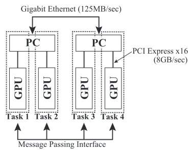
In Fig. 2, we show the schematic view of the system of multi GPU which is used in this study. Two GPUs are mounted on same computer, and these are connected by PCI Express x16. The transmission rate of PCI Express x16 performs 8 GB/sec. And two computers contain two GPUs are connected by Gigabit Ethernet, and the transmis-sion rate of Gigabit Ethernet performs only 125 MB/sec. That is to say, the transmission rate of PCI Express is much faster than that of Gigabit Ethernet.
We consider the set of GPU and CPU as single pro-cessing unit, and the tasks are scattered to each process-ing units (see Fig. 2). Each task is communicated by usprocess-ing MPI even if GPUs are implemented on same computer. Al-though a number of threads in an one block on GPU is fixed as 128, number of block changes its value as the following equation.
Mblock=
N Mthread.
(3) Here,Ndenotes a dimension size of the linear system and
Mthreaddenotes a number of threads. Furthermore,X
de-notes a ceiling function.
At the procedure of inner product calculation in the GPU code, vectors are divided into some blocks and the blocks are scattered to each thread in order to parallel pro-cessing. After finishing the calculation in all threads, we have to gather the results from each thread and to add each other to get the solution of inner product. It is well known that it takes large access time from GPU to main mem-ory so that it is a standard tactic to avoid the access to the main memory as much as possible. However, it is faster to
Fig. 2 The schematic view of the system of multi GPU which is used in this study.
Table 1 Evaluation environment.
OS Ubuntu Linux 10.04 x86 64
kernel 2.6.32
CPU Intel Core i7 930
CPU Memory 12GB
CPU Compiler gcc 4.5
CPU Compiler Option -O3 -fopenmp
GPU GeForce GTX 480
GPU Memory 1.5 GB
GPU Compiler nvcc 3.1
GPU Compiler Option -O -arch=sm 20
execute the procedures of gathering the results from each thread and adding each results by CPU than that of GPU. From the above reasons, a part of convolution operation is operated not only by GPU but also by CPU in the inner product calculation.
Throughout this paper, parameters are fixed as fol-lows: Mthread =128, termination condition for outer-loop
εout = 1.0×10⁻¹⁰, termination condition for inner-loop
εin = 1.0×10⁻³. Besides, the evaluation environment is
shown in Table 1.
The performance of iterative method for linear system obtain by FEM with an edge element is investigated. We compare four cases of the systems. The Case 1 uses four cores on one CPU. The Case 2 uses two CPUs are con-nected by Gigabit Ethernet, and the total number of core is eight. In the case 3, two GPUs are used for evaluation. Two GPUs are implemented on same computer and these are connected by PCI Express x16. Finally, four GPUs are used in the case 4. Two PCs are connected by Gigabit Ethernet. Note that all the communication is executed by using MPI.
Fig. 3 Evaluation cases which are adopted in this study. case 1: Four core on unit CPU. case 2: Two CPUs are connected by Gigabit Ethernet, and total number of core is eight. case 3: Two GPUs are implemented on same computer and these are connected by PCI Express x16. case 4: Two PCs which is contained two GPUs are connected by Gi-gabit Ethernet.
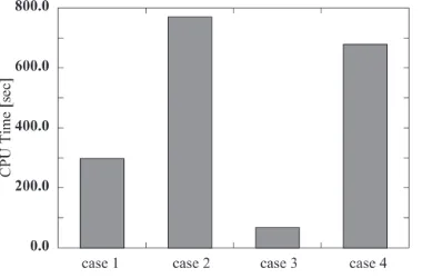
Fig. 4 CPU time of variable preconditioned CG method. CG method is also adopted for inner-loop solver.
Fig. 5 CPU time of variable preconditioned CG method. CR method is adopted for inner-loop solver.
shown in Fig. 5. Although the performance of the case 3 is 4.48 times faster than that of the case 1, the case 4 per-forms 2.04 times more slowly than that of the case 1. These results indicate that the transmission rate between the PC using Gigabit Ethernet is a bottleneck of the performance.
Other reasons are sparseness of the coefficient ma-trix. In the present study, Jagged Diagonal Storage (JDS) is used for the coefficient matrix’s memory storage to get good performance of memory accesses. However, the number of nonzero elements that contains at a maximum in a row is only 32 elements. Accordingly, the distributed tasks are too small for each GPUs, and the tasks are solved in no time. As the result, much time spends for communi-cation between the PUs, relatively.
One of the settlement of reduction of communica-tion time is using the InfiniBand for conneccommunica-tion. As we mentioned above, Transmission rate of GbE preforms only 1 Gbps. In contrast, the InfiniBand with Quad Data rate performs 32 Gbps theoretically. If the InfiniBand is used for transmission, the communication time can be reduced about thirtieth. Thus, CPU time of case 3 will be 8 times faster than that of case 1 if the InfiniBand is used for trans-mission. We can conclude that the InfiniBand between the cluster must be need for the GPU cluster.
6. Conclusion
We implemented the Variable Preconditioned CG method to multi GPU using MPI. The CG method and CR method are adopted for inner-loop solver because the co-efficient matrix of linear system obtained by FEM with an edge element is singular matrix.
Conclusions obtained in the present study are summa-rized as follows.
• The performance of two multi GPU connected by PCIe is 4.35 times faster than that of quad core CPU. However, the case with Gigabit Ethernet performs 2.28 times slower than that of quad core CPU. These results indicate that the transmission rate between the PC using Gigabit Ethernet is bottleneck of the perfor-mance.
• One of the settlement of reduction of communication time is using the InfiniBand for connection. We can conclude that the InfiniBand between the cluster must be need for the GPU cluster.
Acknowledgment
This work was supported in part by Japan Society for the Promotion of Science under a Grant-in-Aid for Sci-entific Research (B) No.22360042. A part of this work was also carried out under the Collaboration Research Pro-gram (No.NIFS09KDBN003) at National Institute for Fu-sion Science, Japan.
[1] S. Ikuno, M. Natori and A. Kamitani, Fusion Energy 1998,
4(IAEA, Vienna, 1999) (Proc. 17th Int. Conf. on Plasma Physics and Contr. Nucl. Fusion Res., Yokohama, 1998) p.1497.
[2] http://gpgpu.org/
(Computa-tional Science ICCS 2009) p.893.
[4] K. Abe and S.L. Zhang, Int. J. Numer. Anal. Model.22, 147 (2005).
[5] http://www.nvidia.com/object/cuda develop.html
[6] http://www.compumag.org/jsite/team.html
[7] H. Igarashi, IEEE Trans. Magn.37, 3129 (2001).
[8] H. Igarashi and N. Yamamoto, IEEE Trans. Magn.44, 942 (2008).
[9] K. Fujiwara, T. Nakata and H. Fusayasu, IEEE Trans. Magn.