Integrated Accident Detection & Reporting System
Fatma AL Saadi1, Mohammed AL Jabri1, Suliaman AL Hasani1Depatment of Electronic and Telecommunication Engineering Global College of Enginnering and Technolgy
Muscat, Sultanate of Oman
Abstract: Many people around the world use their privtae vehicles as the main method of their daily transportation. Although, the use of such a method has its advantages, road accidents are very common and is considered as one of the leading causes of fatalities. Difficulties and delay in getting help on time after a road accedient, is one of the factors that ranks road accedients as a leading cause of death. One way to minimise the severity of this, is to equipe vehicles with an integrated Accident detection & reporting system. Hence, this paper presents an intelligent framework that can find the nearest location and report an accident place. This paper propose accident detection and reporting system by using GPS and GSM. The objective of this system to minimize the delay of reaching the rescue in the accident location. This scheme is fully automated. Thus it locates the accident spot accurately, calculates the distance, selects the nearest emergency station to the accident location and then sends alerting message to the selected location. Many kinds of research are heading to develop the features of the airbag. However, the success of any safety equipment depends on its correct implementation and specific rules to be followed.
Keywords—Global Position System Introduction-GPS, Global System for Mobile Communications (GSM), Subscriber Identification Module- SIM, Short Message Service-SMS
1. Introduction
The rapid growth in the vehicular system has a significant impact on globalization and economy. In contrast, it brings disaster as with growing population the number of vehicles is increasing in the road leading to traffic and road accident as it has become one of the vital reasons for death all over the world. According to Annual Global Road, Crash Statistics were done by world health organization (WHO), average 3.287 deaths per day, approximately 1.25 million people die yearly in road crashes. Moreover, 20-30 million are injured or disabled. Besides road accidents cost each year $65 billion for low and middle-income countries. If no action is taken by 2030 expected that road accident to be the fifth leading cause of death (Association for Safe International Road Travel, 2019). Various researchers have concluded that the number of road traffic injuries is increasing due to the response time of emergency services, which is the time between the accident and the emergency response time. Consider being one of the most critical factors affecting.
According to a recent study by Sherafati et al. (2017), they investigated that number of people dying due to road accident is different from urban and rural regions. This differences in number of death due to time of reaching emergency services. Their result showed that the high rate of fatal accidents could be decreased by lessening the gap of access to health care services between urban and rural regions. Lately, there have some attempts to improve an automated system for car accidents in different situations. If these problems not handled in right way this will effect on the application of smart crash detection systems. Hence, the national highway traffic safety and administration (NHTSA) and other road-related safety authorities have called for compulsory consideration of crash detection in vehicles (Hanan et al. 2010) The focus of this paper has on passive safety system. Crash detection played a vital role in
a successful passive safety system in order to save human lives by the immediate response of rescue services via early accident detection. Moreover, this project focuses on sensors used in accident detection that activate the passive safety system the GPS and the GSM will be interfacing with each other. Global Positioning System (GPS) is used to identify the location of the vehicle. GSM is used to inform emergency station' hospitals or police stations' the exact vehicular location, hence a message will be sent including the geographical location of the vehicle longitude and latitude values. These values will determine the accident location; also a cancelation option provided in this system if the driver thought the alert not necessary.
2. Literature Survey
After analyzing the requirements of the project, the next step is to research and analyze the earlier works done related to the project. The proposed system design includes analysis of the following research paper: In a recent study (Hussain et al. 2015) they developed a system, that when an accident happens the sensor in the vehicle will send messages to the primary server, this will alert the nearby ambulance to the accident site and provide it with exact location the accident. Then the control unit will provide the ambulance with the shortest path and green the traffic light to reduce the waiting time. One of the limitation for this project was the path provided can be affect the red lights or sudden traffic in the path. On the other hand, another study had done by (Goud et al., 2012) they introduce a system of Automatic Vehicle Location (AVL), this system is developed to adjust with the needs of the modern world in different cases such accident and theft condition. As this system consists of two main sections: First part provides the vehicle with tracking service based on GPS as it communicates with satellite to get the coordinate of an object. Second part when the accident takes place to send
SMS to a phone number of the owner with a link or location using Google earth map. They add two more features in case of theft and accident preventing. Moreover, they mentioned the accuracy issues of GPS reading. Further, Kumar et al. (2014) and NiravThakor et al. (2013) developed a system the central concept is same that provides information of a vehicle when the system detects accident with the help of vibration sensor or MEMS sensor. Both systems use a MEMS sensor, GPS, and GSM to identify the accident. Also with the help of the ARM controller, locate vehicle location information (latitude, longitude) this information send to authorized people. However, Nirav Thakor provided their system with a new facility, and it offers help if needed due to any reason as the help will be given to the person. When a person requires help due to other reasons like having symptoms of heart attack. If he faces a similar situation he has to do is to press a single switch provided in the system. By pressing this switch, a message will is transmitted from the GSM module to the help center which contains the location of the car provided by GPS with the information about the user.
3. System Architecture
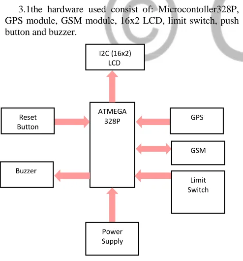
As shown in the system block diagram that the heart of the project, which connects and allow all components interfacing together, has been used, as the microcontroller is based on Arduino UNO ATMEGA328P. The complete block diagram is as shows in figure 3.1:
3.1the hardware used consist of: Microcontoller328P, GPS module, GSM module, 16x2 LCD, limit switch, push button and buzzer.
1.Arduino Uno
Arduino Uno define as a microcontroller board based on 8-bit ATmega328P microcontroller. In company with ATmega328P, it contains other components for instance
crystal oscillator, serial communication, voltage regulator, etc. All these used to support the microcontroller, it has 14 digital input/output pins (6 of them can be used as PWM outputs), 6 analog input pins, a USB connection, a Power barrel jack, an ICSP header and a reset button
2. GSM module
The A6 GSM Module is a mini GSM/GPRS core development board based on GPRS A6 module. Furthermore, it supports dual-band GSM/GPRS network, available for GPRS and SMS message data remote transmission. The board features compact size and low current consumption
3. GPS Module
NEO-6M GPS Module is a very capable GPS for the price and size. So, after the module is plugged with power as it will automatically obtain satellite signals and a position fix 4. 16x2 LCD
16x2 LCD display screen with I2C interface as LCD (Liquid Crystal Display) screen is an electronic display module. It is a very basic module and is very commonly used in various devices and circuits. . A (16x2) LCD means it can display 16 characters per line and there are 2 such lines. This I2C 16x2 Arduino LCD Screen is using an I2C communication interface
5. Buzzer
Electromechanical, or piezoelectric (PIEZO for short). The type used in this project is Piezo buzzer. It defined as an electronic device generally used to produce sound.
6. Micro Limit Switch
A miniature snap-action switch also trademarked and
commonly known as a micro switch, is an
electromechanical device that consists of an actuator, as it actuated by very little physical force, via the use of a tipping-point mechanism
7. Push Button
Miniature 2-PIN Single Pull Single Throw switches. These are high quality momentary on switches which are NO Normally Open. In this project it used for reset the circuit when there is no need for the ambulance or the police 3.2 Software components
1. Arduino Software
ARDUINO Software (IDE): The Arduino integrated development environment (IDE) is an area application (for Windows, macOS, Linux) that is written in the programming language Java. Languages C and C++ are supported by Arduino IDE by using special rules of code structuring
2.EAGLE Software
EAGLE, an abbreviation for Easily Applicable Graphical Layout Editor, is an electronic design automation (EDA) software by Cadsoft Computers. In addition, enabling the designers of the printed circuit board (PCB) to seamlessly connect many things such, schematic diagrams, component placement, PCB routing, and comprehensive library content
3. Fritzing ATMEGA
328P GPS
GSM
Limit Switch Reset
Button
Buzzer
I2C (16x2) LCD
Power Supply
Fritzing is an open-source initiative to develop amateur or hobby CAD software for the design of electronics hardware, to support designers and artists ready to move from experimenting with a prototype to building a more permanent circuit
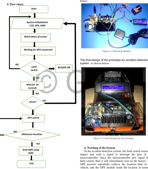
4. Flow chart:
5. Implantation:
After building the system in breadboard, assuring its working as required. Then, by using the EAGLE software the circuit is designed in PCB then all the components is soldered in PCB. When the PCB is ready the systems is tested as shown below:
The final design of the prototype for accident detection system as shown below:
6. Working of the System
In the accident detection system, the limit switch senses an impact and send a signal to interrupt the pins of the microcontroller. Once the microcontroller gets signal from limit switch, then it will immediately turn on the buzzer. The GPS receiver repeatedly collects the location data of the vehicle, and the GPS module sends the location in terms of latitude and longitude to the microcontroller. At the initial Reset?
Read status of sensor
Waiting for GPS connected System initialization
LCD, GPS, GSM
Limit switch pressed?
Send SMS using GSM
Start
End Wait for 10
seconds
GPS search NO
BUZZER ON
YES
NO
Minimum=location YES
YES NO
Fig.4.1 Oprentional flow chart for entire system
Figure 5.1 Working Module
stage, the prototype module has been powered up by using a 9V battery for the microcontroller board and another 9V for the GSM module. Moreover, the detection system is used for the vehicle, so the car battery can be used to provide power to the system.
GSM module is run by using AT command in the program of Arduino. Initially, the network registration is done by using AT+CREG and set Access Point Name (APN), user name and password. Furthermore, turn on the GPS power supply using the command CGPSPWR and current GPS location information can be gotten using AT+CGPSINF command and then applying haversine formula in the code to calculate the distance between Geo-location latitude and longitude. Besides a minimum function used in the code for selecting the least number which allocates the nearest location.
After getting the data of the vehicle's location, now the data is sent to the selected location which represents the system emergency station. For sending SMS, AT+CMGS command is used in the program, and AT+CMGR command is used to read the SMS which has been sent from the user. The SMS which sent include the location of the vehicle can be viewed through a Google map link attached. A key will be provided for cancelling sending message for the driver in case the accident is small and doesn’t require help.
7. Results:
The system detects accident from the vehicle and sends a message through GSM module. Another GSM module receives the message. A link is attached with the SMS so that the emergency station can display the exact location of the accident and its details Via Google map. Moreover, it gets detail SMS from the location of the accident. Hence there is a small variation in the coordinates, the initial value of latitude and longitude are same but fractional value changes with a small difference. Within 10 seconds if the reset button not pressed, GSM will send a message to the emergency station The example of text received when the accident occurred. It is seen that the text message consists of the coordinates in the form of Latitude and Longitude can be displayed in the Google map link. Also, it includes the name of the place and some detail of the victim as shown in the figure 7.1.
8. Discussion
The output of the project is to build a system able to detect an accident and reported it to the nearest emergency station. From the output, results have confirmed that when limit switch transfer impact signal to the microcontroller which it interfaces with GPS to read the location coordination than a haversine formula used. For the testing purpose the code includes five fixed places selected represent the emergency station. For example from the result assume the accident occur in location x, so the system will work in a way to calculate the distance between the location and fixed location one by the time the location is shown in the map see fig.8.1.
Fig.7.2: Display the location from the messagein Google map
From the table the system able to calculate the distance between the accident location x and the five fixed locations using haversine formula at the same time. The haversine formula uses to calculate the great-circle distance between two points that is the shortest distance over the
Where, R is earth’s radius (mean radius = 6,371km). 9.Conclusion
In this project, we have successfully designed a vehicle accident detection and reporting system by using GPS and GSM. Moreover, experimental work has been carried out carefully. Instead of using the crash sensor in airbag system the test done on the limit switch which is connected to the microcontroller, when there is an impact it transmits the signals to the microcontroller. This system can be fit in the vehicle as a portable device which has an input for connection with an airbag system. Also, the system provides care response which able the system automatically select the nearest emergency station to the accident location as it has artificial intelligence. The proposed method is defined to be highly beneficial for the automotive industry. Also, the device can provide an efficient way to inform accidents and accurate reporting system by selecting the nearest emergency.
10.Further work:
• The system could be connected to a database or cloud system to have all the data of the emergency station and has a direct connection with them.
• Developing the system method to be able to define different accident levels
• Develop the system by interconnection the camera with microcontroller to take images of the accident spot.
• The system can be improvised by adding more components to know the state seatbelt, the speed of the vehicle and the braking system
• Add a face recognition algorithm focusing on the eyes of the driver, and continuously monitor the consciousness of the driver.
11.Refrences:
• Association for Safe International Road Travel. (2019). Road Safety Facts — Association for Safe International Road Travel. [online] Available at: https://www.asirt.org/safe-travel/road-safety-facts/ • Hannan, M., Hussain, A. and Samad, S., 2010. System interface for an integrated intelligent safety system (ISS) for vehicle applications. Sensors, 10(2), pp.1141-1153
• Goud, V., 2012. Vehicle accident automatic detection and remote alarm device. International Journal of Reconfigurable and Embedded Systems, 1(2), p.49.
• Sampalis, J.S., Denis, R., Lavoie, A., Frechette, P., Boukas, S., Nikolis, A., Benoit, D., Sherafati, F., Rad, E.H., Afkar, A., Gholampoor-Sigaroodi, R. and Sirusbakht, S., 2017. Risk factors of road traffic accidents associated with mortality in northern Iran; a single center experience utilizing Oaxaca blinder decomposition. Bulletin of Emergency & Trauma, 5(2), p.116.
• Thakor, N., Vyas, T. and Shah, D., 2013. Automatic vehicle accident detection system based on ARM &GPS. International Journal for Research in Technological Studies, 1(1), pp.17-19.
• Thakor, N., Vyas, T. and Shah, D., 2013. Automatic vehicle accident detection system based on ARM &GPS. International Journal for Research in Technological Studies, 1(1), pp.17-19.
[1] G. Eason, B. Noble, and I. N. Sneddon, “On certain integrals of Lipschitz-Hankel type involving products of Bessel functions,” Phil. Trans. Roy. Soc. London, vol. A247, pp. 529–551, April 1955.
(references)
[2] J. Clerk Maxwell, A Treatise on Electricity and Magnetism, 3rd ed., vol. 2. Oxford: Clarendon, 1892, pp.68–73.
[3] I. S. Jacobs and C. P. Bean, “Fine particles, thin films and exchange anisotropy,” in Magnetism, vol. III, G. T. Rado and H. Suhl, Eds. New York: Academic, 1963, pp. 271–350.
[4] K. Elissa, “Title of paper if known,” unpublished.
[5] R. Nicole, “Title of paper with only first word capitalized,” J. Name Stand. Abbrev., in press.
[6] Y. Yorozu, M. Hirano, K. Oka, and Y. Tagawa, “Electron spectroscopy studies on magneto-optical media and plastic substrate interface,” IEEE Transl. J. Magn. Japan, vol. 2, pp. 740–741, August 1987 [Digests 9th Annual Conf. Magnetics J
Point color Name of
location
The distance from
the accident location
Yellow Loc 1 22.886 KM
Brown Loc 2 12.1 KM
Green Loc 3 10.25 KM
orange Loc 4 35.767 KM
Blue Loc 5 9.6 KM
Pink Accident location Lat =23.5737392;