The use of wireless technologies for critical surveillance and home automation introduces a number of opportunities as well as technological challenges. New emerging technologies give the opportunity to exploit the full potential of the internet of things paradigm by augmenting existing wired installations with smart wireless architectures. This work gives an overview of requirements, characteristics, and challenges of wireless home automation networks with special focus on intrusion detection systems. The proposed wireless network is based on several sensors that are deployed over a monitored area for detecting possible risky situations and triggering appropriate actions in response. The network needs to support critical traffic patterns with different characteristics and quality constraints. Namely, it should provide a periodic low-power monitoring service and, in case of intrusion detection, a real-time alarm propagation mechanism over inherently unreliable wireless links subject to fluctuations of the signal power. Following the guidelines introduced by recent standardization, this paper proposes the design of a wireless network prototype at 868 MHz which is able to satisfy the specifications of typical intrusion detection applications. A
proprietary medium access control is developed based on the low-power SimpliciTI radio stack (Texas Instruments Incorporated, San Diego, CA, USA). Network performance is assessed by experimental measurements using a test-bed in an indoor office environment with severe multipath and nonline-of-sight propagation conditions. The
measurement campaigns highlight the potential of the sub-GHz technology for cable replacing.
Keywords: Wireless home automation networks (WHAN); Internet of things; Smart spaces; Wireless sensor networks; Smart surveillance
1 Introduction
Wireless sensor network (WSN) technologies are expec-ted to be integraexpec-ted into the so called internet of things, allowing for the global interconnection of heteroge-neous smart objects with advanced functionality. Recent advances of microcontroller design and radio technolo-gies have opened the way to an emerging category of wire-less network-enabled sensors that serve as smart agents equipped with a low-power dedicated high-performance microcontroller and a large memory space. Those devices are now gaining the attention of companies operating in the field of smart spaces and advanced surveillance sys-tems. Although most solutions currently on the market are still based on power line or wired communications,
*Correspondence: [email protected]
3Institute of Electronics, Computer and Telecommunication Engineering (IEIIT), Italian National Research Council (CNR), Milan site, c/o DEIB Politecnico di Milano, via Ponzio 34/5, 20133 Milano, Italy
Full list of author information is available at the end of the article
it is expected that cable replacing will eliminate time-consuming installations [1], opening the way to more flex-ible services for the end user. A wireless home automation network (WHAN) is thus the key enabling technology to make indoor environments intelligent and context aware.
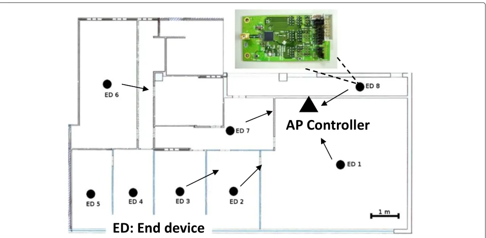
A WHAN is composed by a number of sensors and actuators (e.g., infrared, motion sensors, light switches, safety sensors, accelerometers) that intelligently share their transmission resources and interconnect with each other according to a suitable wireless architecture. As depicted in Figure 1, a network coordinator or access point (AP) is responsible for starting the network, assign-ing radio resources, monitorassign-ing the links’ quality, and joining new end devices (ED). ED nodes can be spread over the area of interest (typically indoor and over differ-ent floors) while the communication with the AP coor-dinator might be guaranteed by range extenders (RE) serving as decode and forward relays.
Figure 1Map of the indoor scenario of application and WHAN deployment with an AP controller and 8 EDs.
A key element for WHAN design and implementation is to provide efficient hardware-software supporting infras-tructures and middleware platforms to enable consistent and cost-effective interactions among the diverse actors participating to the smart space environment. Motivated by this vision, in this paper, we consider the design of the medium access control (MAC) for a wireless network sup-porting critical home automation services, with special focus on indoor surveillance and intrusion detection. The system needs to periodically record activities in the envi-ronment and provide a highly reliable connection service for alarm message propagation [2]. The general require-ments of wireless intrusion detection systems, evaluated at European level through the standard EN 5013-5-3 [3], are discussed in the first part of the paper. Next, we provide an overview of wireless solutions suited for the selected application, and we propose a performance comparison between two candidate radio technologies operating at 2.4 GHz and 868 MHz based on experimen-tal tests in indoor environments with severe multipath and nonline-of-sight (NLOS) propagation. The measure-ment campaigns highlight the potential of the sub-GHz radio technology for home automation as compared to the more conventional 2.4 GHz option. Based on the results of this experimental analysis, we then focus on the sub-GHz radio technology and consider the implementation of the proposed MAC sub-layer on radio modules oper-ating over the 868-MHz ISM band. The guidelines and general rules for the development, and the configuration and the network planning of the WHAN are proposed and tailored to the specific application. The analysis of battery
consumption, wireless connectivity, and robustness shows that the proposed system is a promising solution for surveillance and intrusion detection applications.
2 Requirements and protocols for wireless indoor
surveillance
A WHAN for smart surveillance and intrusion detec-tion has many peculiarities that are common to a broader class of industrial automatic control systems. The phys-ical (PHY) layer radio characteristics mostly common to all these systems are low data rate (below 500 kbps), car-rier frequency at 2.4 GHz or in the 868/915-MHz ISM bands, and receiver sensitivity above−110 dBm [4]. Most of the PHY layer access schemes are based on offset quadrature phase-shift keying (O-QPSK) or frequency-shift keying (FSK) combined with direct-sequence spread spectrum (DSSS) transmission which allows the net-work susceptibility to interference to reduce, provid-ing a few dBs of link gain and some improvements over harsh environments characterized by multipath fad-ing. Multi-channel radios are also adopted to efficiently manage the co-channel interference and to reject any external disturbance through dynamic scheduling and channel/frequency hopping.
The basic requirements that need to be considered for WHAN protocol design are listed in the following.
between reliability and real-time communication. • Indoor radio planning. Indoor home environments
are typically characterized by severe multipath due to the presence of reflective surfaces (e.g., walls, floor, and furniture) [4]. Radio planning is a useful tool which relies on the prediction of the wireless link quality. Prediction can be supported by independent radio measurement campaigns over typical indoor buildings and/or by empirical propagation models. A low accuracy in the radio planning design phase will turn into high logistic costs: adding new wireless REs to improve the coverage as well as moving them around the environment may become unacceptable and highly time consuming in some cases.
• Low duty cycling operation. Wireless autonomous devices are battery powered. EDs are usually deployed in predefined spots and must remain active for 3 to 5 years. This poses stringent constraints on the sensor and the radio transceiver design for minimizing the energy consumption. The MAC sub-layer protocol and the application software need to be jointly optimized to preserve the battery. Energy harvesting techniques also provide a powerful tool for lifetime maximization. Some of the techniques employed to reduce power consumption include: (1) dynamic sleep mode activation (with fast wake-up times) to shut-down devices when not transmitting or
receiving and (2) low duty cycling design to minimize ED activity cycles. Being the network almost static, the adoption of guaranteed (interference-free) time-division multiple access (TDMA) and beacon-enabled network designs [5] are to be preferred compared to random access strategies to minimize idle listening.
2.1 Indoor surveillance systems: EU specifications
European wireless intrusion-detection systems are gov-erned by the EN 5013-5-3 [3] law that disciplines several aspects like the immunity against channel variations and transmission collisions, the detection of device substi-tutions, and the robustness to radio interference. The same rules explain how to test every single device to ensure the compliance of the intrusion-detection system
to 6 dB, grade 3 to 9 dB, and grade 4 to 12 dB. • Transmission collisions. The objective of the collision
rate requirement is to ensure a high level of confidence during the transmissions of alarm and monitoring messages to avoid auto-interference (interference among devices of the same system). The collision rate depends on the channel occupation time (or duty cycle) of the devices. Grade 1 service is characterized by a duty cycle larger than 10% measured over 240 min, duty cycle for grade 2 is lower than 5% over a period of 240 min (or 10% over a period of 120 min), while duty cycles for grades 3 and 4 are lower than, respectively, 10% and 1% measured over a cycle time period of 100 s. Notice that a more stringent 1% duty cycle limitation is applied to low-power wireless communications over ISM frequency bands.
• Link reliability. The link reliability measures the probability of information loss during the communication. It is set to10−3for grades 1 to 2 (corresponding to 999 correctly interpreted messages out of1, 000[3]) and to10−4for grades 3 to 4 (corresponding to9, 999correct messages out of 10, 000). For wireless communication over harsh indoor propagation environments, the use of direct/indirect retransmissions (if allowed) can be optimally designed to comply with such specifics. • Security. In order to prevent both unintentional and
intentional device substitution, each transmitter shall be identified by an identification code. The security levels are characterized by the probability for an intruder to discover the identification code in less than 1 h: this is 5% for grade 1, 1% for grade 2, 0.5% for grade 3, and 0.05% for grade 4.
• Cross-tier interference. The system robustness against cross-tier radio interference is measured in terms of in-band and out-of-band interference. Let
FminandFmaxbe the minimum and maximum carrier frequencies: the out-of-band carriersF1and
F2are defined asF1=0.95·Fmin andF2=1.05·
intensity of 10 V/m, while grades 3 and 4 systems are also robust to an in-band interferer centered on the carrier frequencyFt=(F1+F2)/2with an intensity of 10 V/m.
• System monitoring. The measurement of the noise and the interference level is implemented by a periodic message exchange. The period interval for link quality sensing depends only on the transmitter role in the system (e.g., ED or RE devices) and on the network topology. From grade 1 to grade 4, the system has to guarantee that the time interval is not greater than 60 min, 20 min, 100 s, and 10 s, respectively. • Antenna protection. Grades 1 and 2 are assigned if
the antennas cannot be removed without opening the housing, while grades 3 and 4 are assigned if the antennas fulfill the same tamper protection requirements valid for the corresponding devices.
2.2 Wireless protocols for home and building automation
In the following, a review of the most suitable commer-cial systems for wireless networking in home and building automation is presented. The selection criteria include frequency bands, data rates, modulation techniques, rout-ing schemes, topologies, interoperability, openness of the software architecture, standardization, and general suit-ability to support critical home automation applications and security [6].
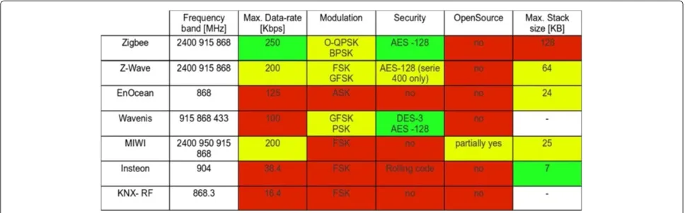
Bluetooh (Bluetooth Special Interest Group, Kirkland, Washington, USA) and ZigBee (ZigBee Alliance, San Ramon, CA, USA) have been recently investigated in the literature for WHAN applications. A Bluetooth WHAN has been introduced in [7] using a primary network con-troller and a number of sub-concon-trollers connected by star topology. However, the wireless architecture does not completely replace cabling, and the use of the Blue-tooth technology shows disadvantages in terms of access delay. A ZigBee-based WHAN has been proposed in [8]. Although ZigBee interface based on the IEEE 802.15.4-2006 standard [9] provides an effective network solution for low-power wireless sensing, the overall size of the radio stack (between 45 and 100 kb) limits its applications to a small subset of smart home automation scenarios. ZigBee is briefly reviewed in the following together with a selection of wireless technologies that present interesting characteristics for WHAN applications. The comparative analysis is also summarized in Figure 2.
ZigBeeis a wireless networking technology developed by ZigBee Alliance for low data rate and short-range applica-tions [8]. Protocol stack is composed of four main layers. The first two layers (PHY and MAC) are defined by the IEEE 802.15.4 standard, while the network (NWK) and application (APL) layers are defined by the ZigBee speci-fications. The standard IEEE 802.15.4 [9] is a specification for low-power WSN originally designed for the frequency
bands 868 to 868.6, 902 to 928, and 2,400 to 2,485 MHz. For the 2,400 - 2,485 MHz band, the PHY layer transmis-sion maps any 4-bit codeword into a 32-chip sequence using DSSS with a bandwidth expansion factor of 8. The chip sequences are concatenated, modulated, and trans-lated to radio frequency (RF) using O-QPSK modulation. Today, commercial battery-operated systems enable data to be transmitted at a rate of up to 250 kbps, while a maxi-mum power of 12 dBm guarantees a reasonably high chan-nel immunity against deep fades (up to grade 4). In critical environments, the transmit power could not exceed 12 dBm to meet the RF regulations for the use of unlicensed spectrum in hazardous environments. ZigBee upper lay-ers support two methods for channel access, the beacon-less and the beacon-enabled access. In beacon-beacon-less mode, devices employ a plain carrier sense multiple access with collision avoidance (CSMA/CA) scheme based on the low power listening principle. The use of CSMA as access technology for all sensors is unsuitable for critical delay-sensitive applications such as intrusion detection systems subject to real-time constraints. On the other hand, in beacon-enabled mode, a coordinator node (i.e., the per-sonal area network coordinator) acts as a clock distributor to provide a framing structure by periodically transmit-ting beacon frames. The frame is the time between two beacons, and it is divided into three parts: a contention-access period for CSMA/CA, a contention-free period for TDMA, and an inactive period to power-off devices.
The Z-Waveprotocol (Zen Systems, Hillsborough, NJ, USA) [10] was developed with an explicit focus on home control applications. Z-Wave operates at 908 MHz in the US and in the ISM band of 868 MHz in Europe, using FSK modulation with data rate 200 kbps. Z-Wave uses a mesh networking approach with source routing, which means that the whole route is determined already at the creation of the frame in the sender. Therefore, only devices which are aware of the entire network topology can send
ad hoc messages to any destination. Z-Wave consists of several types of nodes that can be clustered into two main classes, controllers (nodes that create and send con-trol messages) and slaves (nodes that receive and execute the commands). The standard is specifically tailored for remote control of devices used in both residential and commercial buildings. However, the protocol has not been designed to transfer large amounts of data, and it is not suitable for real-time critical data transmission.
Figure 2Commercial wireless systems, standards, and software architectures for home and building automation.Green (and yellow) cells indicate desired (and acceptable) features for home automation applications. Red cells highlight critical issues that need to be accounted for during system design.
bytes) and are transmitted using amplitude shift keying (ASK) modulation at the data rate of 125 kbps. Packet transmission takes less than 1 ms. The EnOcean protocol cannot increase the transmission reliability by means of end-to-end acknowledgments since its battery-less trans-mitter modules do not contain a RF receiver. No security mechanisms appear to be included.
Wavenisis a wireless protocol operating at 868, 915, and 433 MHz, developed by Coronis System (Pérols, France) for monitoring and control applications in several envi-ronments such as homes and buildings [4]. The standard Wavenis, currently promoted and managed by Wavenis Open Standard Alliance, supports data rate up to 100 kbps and adopts Gaussian frequency-shift keying (GFSK) mod-ulation in conjunction with fast frequency hopping spread spectrum (FHSS). It defines the operations at the PHY, data link and NWK layers, delivered through proprietary APIs.
MiWi wireless protocol [12], developed by Microchip Technology (Chandler, AZ, USA), uses low-power radio systems based on IEEE 802.15.4 for short-range transmis-sions. Given the small size of the protocol stack, MiWi-based solutions are an alternative to ZigBee for low-cost applications requiring small memory space and able to operate on simple low-cost micro-controllers. The system is based on the IEEE 802.15.4 recommendations for wire-less personal area networks (WPAN). It supports a smaller number of functions compared to ZigBee, and it is meant for simple networks with either peer-to-peer, star or mesh topologies in beacon-less configuration. MiWi provides advanced functionality at PHY, MAC, and NWK levels, all accessible through the use of proprietary APIs.
Insteon technology is developed by SmartLabs, Inc. (Irvine, CA, USA) and promoted by the Insteon Alliance for the field of home automation [13]. The system utilizes a dual technology to support communication between
devices: it employs both powerline communications with X10 protocol and wireless communications using FSK modulation at 900 MHz. All Insteon compliant devices are peers, which means that each device is able to trans-mit, receive, and repeat any message compliant with the Insteon protocol, without the need of a master con-troller or routing software. The powerline communication infrastructure is used to provide synchronization to the wireless system.
KNX-RF (KNX Association cvba, Diegem, Belgium) is a wireless solution specified in Supplement 22 of the KNX specification for cable based systems [14]. Thereby, KNX is not a protocol tailored for radio-frequency com-munication, but rather a home and building automation standard based on wired media that has been extended to support wireless communications. KNX RF operates at 868 MHz using FSK modulation at 16.4 kbps. KNX RF allows unidirectional (transmit-only) devices in addition to conventional bidirectional ones. Transmit-only devices cannot be configured thorough the network. Data relia-bility is guaranteed only by APL layer acknowledgements, while link layer acknowledgments are forbidden. KNX RF does not provide any security mechanism. Since the trans-mitted data are neither encrypted nor subject to integrity check, KNX RF cannot fulfill the high demands of security in critical applications.
3 WHAN architecture and MAC design
API compared to the other technologies listed in the pre-vious section and thus allow for a more flexible network design. The proposed MAC sub-layer has a smaller code size (8 to 16 kB), and it allows to efficiently manage the dif-ferent traffic patterns generated by the intrusion detection system, jointly exploiting both synchronized and non-synchronized access schemes. The use of the ISM band 868-MHz radio technology provides an improved robust-ness, compared to 2.4-GHz transceivers, against severe propagation conditions that are typical of indoor environ-ments. This conclusion is confirmed by the experimental analysis illustrated in the next section.
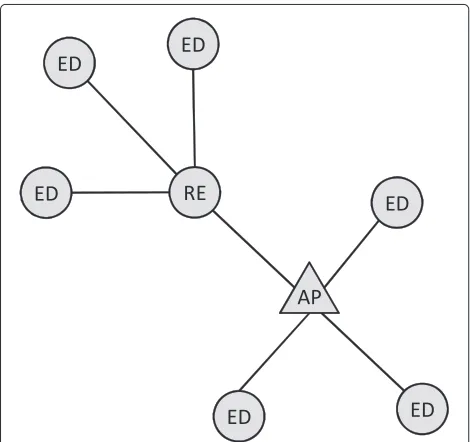
The proposed network architecture, depicted in Figure 3, consists of one AP and a number of REs and EDs. The AP is the network coordinator which manages a low-power radio interface for two-way communications with the remote EDs and acts as a translator over any external network. For the APL layer, the AP node should guarantee the interoperability of the wireless infrastruc-ture with other end-user operator services, i.e., portable human machine interfaces (HMI), radio-frequency iden-tification (RFID), and video camera or thermocamera monitoring. As a consequence, the AP should perform the following tasks: (1) adaptively choose the network resources (through channel hopping and dynamic power control), (2) register new EDs (joining phase) and syn-chronize them to guarantee low duty cycle activity as prescribed by the standard [3], (3) periodically monitor the device status through standard-compliant keep-alive messages, and (4) guarantee real-time alarm message propagation with minimum latency.
Figure 3Node classes: end device (ED), access point (AP), range extender (RE).
The RE is the device responsible for multi-hop commu-nications. Its basic function is to repeat the message from the ED under its control to the AP and vice versa. Finally, the ED is the low-power input/output wireless instru-ment that interacts with the sensor hardware to moni-tor the indoor environment and detect intrusions. Any ED should perform two functions: (1) periodic transmis-sion ofkeep-alive messagescontaining basic information on radio device status (battery residual levels, receiver sensitivity, and channel quality), sensor status and tam-pering, and (2) transmission ofalarm messageswithin a maximum latency of approximately 10 s. Periodic retrans-mission of keep-alive messages conforms to the standard security grade 2 [3] that prescribes a minimum refresh rate of 20 min.
3.1 Network configuration
The network configuration phase allows to register new-comer devices. Devices have to inform the AP about the role, type and number of their sensors in the network. The RE can join the network only by a direct connection. Instead, an ED device can join the network either with direct or indirect - through a RE - connection. In case of indirect connection, the ED communicates with a RE that forwards the message to/from the AP. Routing of packets is established at the time of network configuration.
3.2 Frame structure and traffic management
The MAC sub-layer developed for this experimental study proposes a frame structure that jointly handles the peri-odic traffic for monitoring the sensing device status and the potential bursty traffic for alarm message propagation in case of intrusion detection. The first task is imple-mented through a keep-alive message exchange with ded-icated channel assignments, the second one by random slotted access through CSMA/CA.
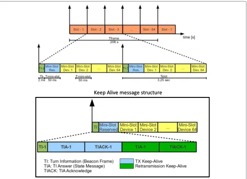
The frame structure is shown in Figure 4. Time divi-sion duplex is employed to separate uplink and downlink, and to avoid transmission collisions. Logical frames have length Tframe = 208 s and consist of 64 time slots of
Tslot= 3.25 s separated by guard times. The frame dura-tion depends on the maximum number of EDs that can be assigned to the network, here set to 64.
Figure 4Frame structure and keep-alive message passing.
of the device indicated in the beacon message (holding the turn). As illustrated in Figure 4 (at bottom), a two-way explicit acknowledgement policy is adopted to guaran-tee reliable message delivery over links subject to fading. This ensures a sufficiently high level of channel immu-nity against short-term fluctuations of the channel gain. The remaining 64 mini-slots are used for synchronization operations and for alarm propagation as indicated below.
For the real-time alarm delivery, any ED detecting an intrusion cannot wait for its reserved mini-slot, it has to propagate the alarm message immediately after detection. The solution here proposed is to use a random access over the abovementioned 64 mini-slots. The ED willing to give the alarm overhears the beacon message (even if intended for another ED) to acquire synchronization, it randomly chooses one of the 64 mini-slots, and it uses carrier sensing before any transmission attempt to avoid cross-tier interference from external devices operating on the same frequencies (e.g., WiFi and Bluetooth). In the worst case, the overall latency of alarm message propaga-tion is two times the slot durapropaga-tion, 2Tslot = 6.5 s. If the first alarm transmission fails due to collision, the ED waits
for a random period (equal to a number of mini-slots) before retransmission. If also the second one fails, the ED checks if the AP had changed channel by performing two retransmissions for each available channel until an ACK is observed.
3.3 Interference-aware channel hopping
Figure 5Message exchange during channel hopping phase.
period is necessary to be sure that beacon miss-detection is not caused by a temporary interferer.
3.4 Duty cycling and device synchronization
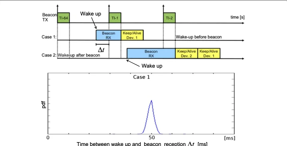
Device synchronization is based on the approach in [5]. A drift error compensation algorithm is developed to mini-mize idle listening and thus maximini-mize the device lifetime. Each ED sleeps during the beacon transmissions intended for other devices and, excluding the alarm transmissions, it wakes up only to reply to its intended beacon mes-sage. The chosen intervalTframeamong successive beacon messages is large compared to typical re-synchronization intervals of 10 to 15 s [5]. Time-synchronized duty cycling is thus guaranteed by correcting and updating the sleep time Tsleep (the time elapsed between two consecutive wake-up phases) on every new beacon message reception
to account for the timing error experienced with the AP local oscillator. The proposed synchronization algorithm allows the ED to turn on the radioTg =50 ms before the beacon message reception, with Tg being a pre-defined
guard time. To account for the residual timing uncertainty after drift correction, the observed interval t between the ED wake-up and the reception of the intended bea-con message is modelled as Gaussian distributed with meanTg=50 ms and maximum jitter of 4 ms. Observed probability density function (pdf ) is shown in Figure 6 at bottom. Given that thekth beacon message is received, the ED device updates the sleep timeTsleep(k)before the next wake-up by the following tracking approach
Tsleep(k)=Tsleep(k−1)+μ(tk−Tg), (1)
where tk = t(k) is the observed time between the ED wake-up and the reception of kth beacon message. Initial value for Tsleep assumes perfect synchronization asTsleep(0) = Tframe −T − Tg. The updating factor is set to μ = 1/2. As demonstrated in the experimental activity in Section 5, a larger guard time (Tg > 50 ms) would cause unnecessary idle listening and higher energy consumption.
The tracking algorithm (1) can be applied when the intended kth beacon message is correctly received: in Figure 6 top panel, this scenario is referred to as case 1. On the other hand, case 2 refers to a scenario where the ED loses the beacon transmission due to a radio interference or a residual clock drift that delays its wake-up. In this case, tracking is not applied while anad hoc
re-synchronization policy is implemented. The ED stays awake to receive the next beacon transmission (intended for the ED holding the next turn). Next, to avoid inter-ference with the transmission of the ED indicated in the beacon, it sends the keep-alive message using a reserved mini-slot chosen among the 64 available mini-slots (see also the framing structure in Figure 4) that follow the first mini-slot reserved for keep-alive message exchange (the reserved mini-slot for re-synchronization is assigned during the network configuration phase).
3.5 Dynamic transmission power allocation
Figure 6Device synchronization and timing error analysis.Top panel: device synchronization assuming two cases: wake-up before beacon reception (case 1) and wake-up after beacon reception (case 2). Case 2 requires re-synchronization using the subsequent beacon transmission. Bottom panel: probability density function of the time between the ED wake-up and the reception of beacon message (the average value of 50 ms equals to selected guard timeTg, maximum jitter is 4 ms).
algorithm is to adaptively adjust the power level PT so that the RSS measurement can be kept within the range (min,max). The two thresholds selected for the experimental activity in Section 5 aremax = −20 and min= −70 dBm.
3.6 Encryption
To improve the security level, all the transmissions are coded with the XTEA encoding scheme [18]. It is com-posed by three main elements which are a 128-bit encryp-tion key, a 32-bit initializaencryp-tion vector, and a 32-bit counter. The initialization vector and the encryption key are set at built-time, while the counter value is determined at the time of the link creation between two or more devices. Devices that have formed the link preserve independent counters.
4 A comparative study between 868-MHz and
2.4-GHz RF technologies for WHAN
Several standards for WHAN operate at 2.4 GHz. This frequency is also adopted in many indoor communi-cation systems such as ZigBee, Wi-Fi, Bluetooth, and cordless phones. In this paper, we selected a radio tech-nology in the 868-MHz ISM band, as the use of sub-GHz frequencies compared to 2.4 sub-GHz involves a twofold advantage, providing a low probability of interference and an increased radio coverage in harsh environments characterized by severe line-of-sight (LOS) blockage, due
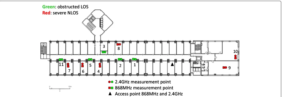
e.g., to walls and furniture in indoor environments. To ver-ify this property, in this section, we present a comparative study between 868-MHz and 2.4-GHz radios based on a number of measurement campaigns carried out over long ranges in the indoor environment illustrated in Figure 7. The goal of the analysis is to demonstrate the impor-tance of optimal frequency choice, taking into account the attenuation factors that highly affect the radiation inside buildings and thus have a crucial impact on network coverage.
4.1 Channel modeling for WHAN
The indoor wireless links without a clear LOS path undergo more severe power attenuations than those where the LOS path is fully unobstructed. This additional attenuation has been shown to be almost uncorrelated with the distance between transmitter and receiver [19]. The main scatterers responsible for the received power attenuation are mostly confined within the first and sec-ond Fresnel zones as these can be considered to contribute to the main wavefield energy [20]. For a wireless link where the direct path between transmitter and receiver has length d, the nth Fresnel zone is the region inside an ellipsoid with circular cross-section. The radius of the section at distanceq≤dfrom the transmitter is [21]
rn(q)=
nλq(d−q)
Figure 7Comparative analysis between 2.4-GHz and 868-MHz technologies.Floor map of the indoor environment (third floor of DEIB building, Politecnico di Milano). Links corresponding to green positions are characterized by a partially obstructed LOS; links corresponding to red positions suffer from severe NLOS. The position of the AP is indicated by a triangular marker; rectangular and circular markers refer to the 868-MHz and the 2.4-GHz co-located devices, respectively.
withλdenoting the signal wavelength (λ = 0.125 m for 2.4 GHz andλ=0.345 m for 868 MHz).
We consider now the wireless linkbetween any two transceivers of the WHAN, deployed at fixed locations and equipped with a single omnidirectional antenna. The RSS is the metric we employ to assess the quality of the radio link: it combines a LOS component and an excess attenuation that accounts for obstructions located within the Fresnel volumes, typically walls and furniture in the considered indoor scenario. The model for the RSS measured in logarithmic scale is [19]
γ=g0−10αlog10
d
d0− σ
g
+s (3)
which consists of (1) a random Gaussian term s ∼
N(0,νs2), with zero mean and standard deviationνs, mod-eling the slow fading fluctuations of the received power due to people or objects moving in the area [22]; (2) a deterministic average term g accounting for the free-space path loss with exponentαand the static multipath fading component [23]σacting as an additional attenu-ation caused by the fixed obstructions located within the Fresnel volume [24]. The term g0 denotes the received power measured over free space (i.e., in LOS) at a refer-ence distanced0(usuallyd0=3m).
The observed value for the path loss exponent can be reasonably set toα =2 in short-range environments [19] where ground reflections can be neglected; this is the case ford < dF, with dF = 2htxhrx/λdenoting the Fresnel distance for antenna heights from the groundhtxandhrx, at transmitter and receiver, respectively. Larger path loss exponent values,α >2, are caused by reflections from the
ground and can be experimented in long-range cases for
d>dF.
4.2 Radio equipment and test description
In what follows, we describe the radio modules employed at the EDs for the comparative study on 868-MHz and 2.4-GHz radio technologies. The module at 2.4 GHz is detailed in [25]. The PHY layer is IEEE 802.15.4 stan-dard compliant. The radio module provides different programmable high-power modes with maximum output power ofPT = 18 dBm and a digital RSSI that facilitates the implementation of the energy detection function. The demodulator is characterized by a minimum sensitivity of βmin(2.4) = −98 dBm. The module is equipped with a low-power 32-bit reduced instruction set computer (RISC) central processing unit (CPU) [25].
The 868-MHz module is part of Digi’s XBee (Digi Inter-national, Minnetonka, MN, USA) family of RF products supporting FSK modulation and a fixed data rate of 24 kbps [26]. The receiver sensitivity isβmin(868) = −112 dBm with maximum programmable output power ofPT = 25 dBm.
For the comparison, the two modules have been pro-grammed to use the same output power, set to 18 dBm so as to handle propagation loss over long ranges and possibly obstructed links. In both cases, we considered omnidirectional antennas with gain of 2 dBi. Antennas with such a gain can be commonly found on the mar-ket and do not require special alignments; the links used vertically polarized antennas.
optimally chooses the channel - out of the available 16 channels - by performing a passive scan to detect possi-ble WiFi signals or co-channel interferers. Before sending data, the 2.4-GHz module of the ED implements an asso-ciation MAC request to acquire the channel selected by the AP.
For the 2.4-GHz front end, the metric adopted to asses the channel quality is the link quality indicator (LQI). As verified experimentally, the LQI reading ranges from 0 to 255, and it is used to compute the link gain L(γ2.4) = LQI× 25585 −7 (see also [25]). The link gain metricL(γ2.4) represents the RSS margin (in decibel scale) with respect to the receiver sensitivityβmin(2.4)as
L(γ2.4)=γ−βmin(2.4), (4) whereγis the observed RSS in (3).
Similarly, the link gain for the 868-MHz radio mod-ule,L(γ868), is computed from the RSSI readingγand the receiver sensitivityβmin(868)as
L(γ868)=γ−βmin(868). (5) The observed RSS γ is directly obtained by reading the 8-bit RSSI register that monitors the automatic gain control state in the RX chain.
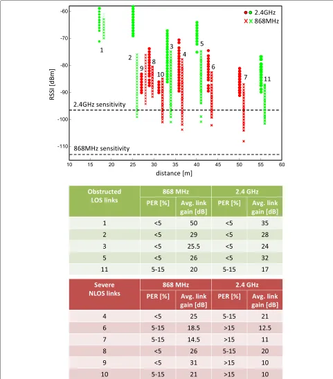
For each ED position and RF module, the values of the measured RSS samples are reported in Figure 8; the cor-responding (average) link gains and the packet error rate (PER) PE are illustrated in the table at bottom. Average link gains with respect to different channel realizations are computed asE[L(γ868)] for 868 MHz andE[L(γ2.4)] for 2.4 GHz.
4.3 Measurement analysis
To highlight the impact of the propagation environment on the wireless system performance, in Figure 7 and 8, the positions and markers in green refer to the links char-acterized by obstructed LOS connection [20], while red markers indicates the links in severe NLOS condition where up to 15 walls are blocking the propagation. In what follows, the analysis focuses on the two propagation scenarios separately.
• Obstructed LOS links. The ED positions labeled as {1,2,3,5,11} are located in an open area along a corridor: the links connecting the ED to the AP are obstructed by obstacles blocking the LOS path, while the first Fresnel volume (see Section 4.1) is only partially obstructed. For the relevant cases where the direct path distance is ranging between 25 and 60 m (positions {2,5,11}), both 2.4-GHz and 868-MHz radio links are characterized by comparable average link margins (notice that RSS measurements are
affected by quantization noise and HW errors of up to 1 dB) and PER values. These fall in the range
E[L(γ2.4)]=17−32 dB for 2.4 GHz and
E[L(γ868)]=20−29dB for 868 MHz.
• Severe NLOS links. The positions {4,6 to 10} are located inside six different rooms at a distance from the AP of 25 to 40 m. The corresponding links connecting to the AP can be classified as severe NLOS being the first Fresnel volume fully obstructed [19]. Obstructions for positions {4,6,7,8} are
characterized by walls 15- to 25-cm thick. The links connecting the EDs located in positions {9,10} are obstructed by a metallic lift structure and walls of larger thickness. By analyzing the corresponding average radio link margins (E[L(γ2.4)] ,E[L(γ868)]), it can be seen that the 868-MHz radio links exhibit improved robustness against multipath effects. The observed link margins are larger compared to those observed for the 2.4-GHz radio modules as
E[L(γ868)]>E[L(γ2.4)]. The average link margin increaseE[Lγ]=E[Lγ(868)]−E[L(γ2.4)]depends on the size of the obstructions, and it falls in the range
E[Lγ]=3.5to6dB for links {4,6,7,8} and
E[Lγ]=11to21dB for positions {8,10}. The corresponding link margins observed for 2.4-GHz links areE[L(γ2.4)]=11to21dB for positions {4,6,7,8} andE[L(γ2.4)]=10dB for positions {9,10}.
Link margins withE[L(γ2.4)]≤20dB cause the PER to exceed the 15% limit. We can thus conclude that the 868-MHz radio technology provides an improved robustness to NLOS propagation typical of indoor environments, and it is thus suited for WHAN applications. This motivated the employment of such a technology for the experimental analysis on the proposed WHAN in the next section.
Figure 10RSS average and standard deviation measured in different rooms during daytime and nighttime.Average (left panels) and standard deviation (right panels) of the RSS measured in different rooms during the daytime (top panels) and nighttime (bottom panels). The RSS samples are averaged over a period of 12 h. Red rooms on the top right panel indicate critical environments, with largest RSS deviation, for network deployment.
5 Protocol testing and experimental activities The 868-MHz radio technology adopted for testing the WHAN architecture and protocol proposed in Section 3 is part of the EM430F6137RF900 Texas Instrument kit with integrated SOC RF XCC430F6137IRGC. Key SOC features are as follows: (1) energy consumption from datasheet is characterized by a receive (RX) absorbed cur-rent of 15 mA, while the transmit (TX) curcur-rent is 33 mA forPT=12 dBm (maximum RF transmit power); (2) radio transceiver module is CC1101 [27] implementing 2-FSK as RF modulation with programmable data rate ranging from 0.6 to 600 kbps; (3) microcontroller unit (MCU) is MSP430 with advanced encryption standard (AES) com-pliant coprocessor, flash memory of 32 kB, RAM 4 kB, and ADC 12 bit.
Experimental activities for protocol testing have been conducted in two different indoor environments con-sisting of eight adjacent rooms. A single wireless ED was deployed in each room to monitor the surrounding area. People were moving inside each room causing ran-dom fluctuations of the radio signals. For all devices, the antenna height from the ground was below 1 m. Prop-agation took place over a harsh radio environment with metallic objects (e.g., coaxial cabling, monitors/PCs, and tubes for air conditioning) and furniture causing signifi-cant attenuation.
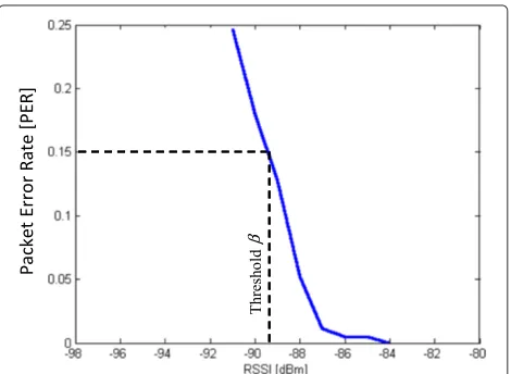
Before presenting the protocol testing, the PER is evalu-ated as a function of the observed RSS. The PER depends on the degree of the RSS fluctuations: successful commu-nication is considered when the RSS is above a threshold βwith probability
PE=Pr[γ≥β] . (6) According to the experimental activity in Section 4, for 868-MHz EDs, the threshold is set toβ = βmin(868) +22 dB −90 dBm, thus assuming a link margin ofL(γ868)=22 dB above the minimum sensitivityβmin(868): this choice guar-antees thatPE ≤ 5%. Direct retransmissions in case of link failures further improve link reliability to a value that is consistent with grade 4 service (see Section 2.2). As depicted in Figure 9, any link experiencingγ< βshould be assumed as unreliable and is thus not considered dur-ing network planndur-ing.
5.1 Channel measurements and network planning
In this section, we analyze the impact of radio propaga-tion at 868 MHz on the wireless alarm message delivery. For the experimental activity, we used eight EDs Texas devices deployed in different rooms and one AP con-troller. The effects of propagation in each office room
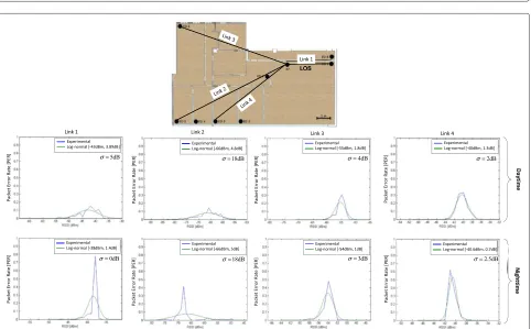
between daytime (top panels) and nighttime (bottom pan-els), it is easy to notice that although the observed average RSS does not change significantly from daytime to night-time, the standard deviation is strongly influenced by the presence of people in the environment during daytime [23]. The behavior of channel fluctuations is thus non-stationary as the degree of fluctuations in some rooms is shown to increase from about 0.5 to 1 dB in the nighttime to more than 4 to 5 dB in the daytime. This suggests to dynamically increase the transmit power during daytime by adding a 4-dB constant fade margin to compensate for the random signal strength fluctuations.
In Figures 11 and 12, the pdf of the RSS measurements is shown for different positions of the EDs, together with the Gaussian fitting curve according to model (3) and the observed attenuationσdue to obstructions for each con-sidered case. The average and standard deviation terms are extracted from the data: for most of the links, the fit-ting between the experimental curves and the Gaussian function is reasonably accurate. In all cases, the RSS stan-dard deviation observed in the daytime is significantly greater than that in the nighttime, due to the effects of human body scattering [28,29]. This effect could also be observed by looking at Figure 13 showing the RSS mea-surements collected as a function of transmitter-receiver distance d during daytime (top panels) and nighttime (bottom panels), respectively. The additional average sig-nal attenuation compared to free-space propagation (for α = 2 in (3)) ranges betweenσ = 2 dB for obstructed LOS environments and up toσ = 14.5 dB under severe NLOS condition. Numerical results match also with pre-vious analyses in the literature (see for example [6] to [30]) that predict RSS fluctuations in the interval 2 to 12 dB.
5.2 Analysis of network lifetime
Figure 14 shows the energy consumption profile of a battery-equipped ED during a normal cycle of remote control. Measurements were obtained through an oscillo-scope connected in parallel with the ED node itself. The absorbed current has been observed during five different phases: the wake-up period (Iwk = 10 mA with duration ofTwk = 4 ms), the receive period (IRX = 23 mA), the
Figure 13RSS measurements as a function of transmitter-receiver distanced.Measurements have been collected during daytime (top) and nighttime (bottom).
state message transmission (ITX = 40 mA for a duration ofTTX=2 ms), the acknowledge reception (Iack=26 mA for a duration ofTack=6 ms) and the sleep mode (Isleep= 8μA). To avoid the high background noise of the oscillo-scope, the current absorbed during the sleep period was measured by a precision ammeter. The values measured during reception and sleep mode differ from the declared power consumptions, respectively 15 mA and 5μA. In the sleep mode, the difference is due to the consumption of the wake-up timer not considered in the datasheet.
Figure 14Energy consumption profile of a battery-equipped ED during a normal cycle of remote control.Left-side panel: measured absorbed current during wake-up, keep-alive receive (RX), and transmit (TX) phases (transmission of ACK message is included). Right-side panel: battery lifetime versus the number of transmitted alarm messages per hour. Guard time of 50 ms uses the proposed drift error compensation for prediction of timing uncertainty; the case of guard time 150 ms does not implement any error compensation. Bottom panel: energy consumption parameters.
For a given mini-slot duration T and frame duration
Tframe, the ED device has been designed to keep the radio transceiver active for receiving the beacon message, send the keep-alive message and the alarm message (if any). The average current absorbedIframe(k)at framekis thus
Iframe(k)=
ηk_alive+ηalarm
ITXTTX+IwkTwk
Tframe + 1− Tsleep(k)
Tframe
IRX+
Tsleep(k)
Tframe
Isleep, (7)
with Tsleep(k) defined in (1). Taking into account the requirements of a grade 4 service that prescribes a duty cycle limitation of 1% measured over a cycle of 100 s, the remote control by keep-alive message exchange is repeated aboutηk_alive =17 times per hour (correspond-ing approximately to 1 message per frame with a device duty cycle of 17×Tslot/3, 6000.01). Therefore, the ED battery lifetime
Tlife=
Cbatt
Iframe(k)+Cbattξd
can be estimated to a maximum of 9 years using a com-mercialCbatt = 1.4 Ah lithium battery characterized by a self-discharge rate ofξd = 0 (per hour) and assuming as ideal caseηalarm=0 alarm messages/hour,Tsleep(k)
Tsleep(0) = Tframe − T − Tg, ∀k, and a guard time of
Tg=50 ms.
In Figure 14, the impact on the expected ED lifetime of the alarm transmission rate ηalarm, the battery self-discharge rate ξd (for ξd = 0 and ξd = 3% per year) and the choice for the guard timeTgis analyzed. We con-sidered two cases: in the first one, drift compensation is employed according to the specifications of the proposed MAC sub-layer with guaranteed guard time ofTg = 50 ms; the second case refers to the use of a guard time of Tg = 150 ms without clock drift compensation. The use of the proposed drift compensation strategy allows significant gains in network lifetime that reaches up to two times for alarm transmission rate below the practi-cal case ofηalarm≤200 messages/hour (corresponding to 200×Tframe/3, 600 messages per frame).
6 Conclusion
Dense Cooperative Wireless Cloud Network (DIWINE) under FP7 ICT Objective 1.1 - The Network of the Future.
Author details
1Dipartimento di Elettronica, Informazione e Bioingegneria (DEIB), Politecnico
di Milano, Piazza Leonardo da Vinci 32, 20133 Milano, Italy.2Comelit R&D s.r.l.,
via Quinto Alpini 6/A, 24124 Bergamo, Italy.3Institute of Electronics, Computer
and Telecommunication Engineering (IEIIT), Italian National Research Council (CNR), Milan site, c/o DEIB Politecnico di Milano, via Ponzio 34/5, 20133 Milano, Italy.
Received: 25 January 2013 Accepted: 21 October 2013 Published: 14 January 2014
References
1. AJD Rathnayaka, VM Potdar, SJ Kuruppu, Evaluation of wireless home automation technologies, inProceedings of the 5th IEEE International Conference on Digital Ecosystems and Technologies(Daejeon, Korea, 31 May–03 June 2011)
2. M Spadacini, S Savazzi, M Nicoli, S Nicoli, Wireless networks for smart surveillance: Technologies, protocol design and experiments, in Proceedings IEEE Wireless Communications and Networking Conference, Workshop on Internet of Things Enabling Technologies(Paris, 1 Apr 2012) 3. European Standard,EN 50131-5-3, Alarm systems - Intrusion systems, Part 5-3: Requirements for interconnections equipment using radio frequency techniques. (CEN, Brussels, 2005)
4. C Gomez, J Paradells, Wireless home automation networks: A survey of architectures and technologies. IEEE Commun. Mag.48(6), 92–101 (2010) 5. W Ye, J Heidemann, D Estrin, An energy efficient MAC protocol for
wireless sensor networks. IEEE INFOCOM.3, 1567–1576 (2002) 6. C Reinisch, W Kastner, G Neugschwandtner, W Granzer, Wireless
technologies in home and building automation, inProceedings IEEE International Conference on Industrial Informatics(Vienna, 23–27 June 2007) 7. N Sriskanthan, F Tan, A Karande, Bluetooth based home automation
system. Microprocess. Microsy.26(6), 281–289 (2002)
8. K Gill, S-H Yang, F Yao, X Lu, A ZigBee-based home automation system. IEEE Trans. Consum. Electron.55(5), 422–430 (2009)
9. IEEE,Standard IEEE 802.15.4-2006, Part 15.4: Wireless medium access control (MAC) and physical layer (PHY) specifications for low-rate wireless personal area networks (LR-WPAN). (IEEE, 2006)
10. T Jorgensen, NT Johansen, Z-wave as home control RF platform, http:// www.zen-sys.com/. Accessed Sept 2012
11. J Ploennigs, U Ryssel, K Kabitzsch, Performance analysis of the EnOcean wireless sensor network protocol, inProceedings of the IEEE Conference on Emerging Technologies and Factory Automation (ETFA)(Bilbao, 13–16 Sept 2010)
12. D Flowers, Y Yang,Microchip MiWi Wireless Networking Protocol Stack. (Microchip Technology, Chandler, AZ, USA, 2010)
13. RJ Robles, TH Kim, A review on security in smart-home development. Int. J. Adv. Sci. Technol.15(2), 13–22 (2010)
14. W Granzer, F Praus, W Kastner, Security in building automation systems. IEEE Trans. Ind. Electron.57(1), 3622–3630 (2010)
15. L Friedman,SimpliciTI: Simple Modular RF Network Specification. (Texas Instruments, Inc., San Diego, CA, USA, 2009)
16. Texas Instruments,Data-sheet, MSP430™SoC with RF Core. (Texas Instruments, Inc., San Diego, CA, USA, 2010)
(2012). doi:10.1007/s11277-012-0558-x
23. P Castiglione, S Savazzi, M Nicoli, T Zemen, Partner selection in indoor-to-outdoor cooperative networks: An experimental study. IEEE J. Selected Areas Commun.31(8), 1559–1571 (2013)
24. WC Lee, DJ Lee, Microcell prediction in dense urban area. IEEE Trans. Vehicular Technol.47(1), 246–253 (1998)
25. NXP Laboratories,Data-sheet JN-DS-JN5148-001, IEEE 802.15.4 Wireless Microcontroller JN5148-001. (NXP Laboratories, UK, 2012)
26. Digi International Inc., XBee-PRO 868 RF Modules, Product Manual, v1x6x XBee-PRO 868, 90001020_B, Digi International Inc.11001 Bren Road East Minnetonka. http://www.digi.com, Accessed Feb 2011
27. Texas Instruments,Data-sheet CC1101, Low-Power Sub-1 GHz RF Transceiver. (Texas Instruments, CA, USA, 2012)
28. S Savazzi, M Nicoli, F Carminati, M Riva, A Bayesian approach to device-free localization: modeling and experimental assessment. IEEE J. Sel. Topics Signal Proc (2014). doi:10.1109/JSTSP.2013.2286772 29. M Cheffena, Physical-statistical channel model for signal effect by moving
human bodies. EURASIP J. Wireless Commun. Netw.77(1) (2012). doi:10.1186/1687-1499-2012-77
30. F Gustafsson, F Gunnarsson, Mobile positioning using wireless networks: possibilities and fundamental limitations based on available wireless network measurements. IEEE Signal Process. Mag.22(4), 41–53 (2005)
doi:10.1186/1687-1499-2014-6
Cite this article as:Spadaciniet al.:Wireless home automation networks
for indoor surveillance: technologies and experiments.EURASIP Journal on
Wireless Communications and Networking20142014:6.
Submit your manuscript to a
journal and benefi t from:
7 Convenient online submission 7 Rigorous peer review
7 Immediate publication on acceptance 7 Open access: articles freely available online 7 High visibility within the fi eld
7 Retaining the copyright to your article