© 2015, IRJET.NET- All Rights Reserved
Page 321
A METHODOLOGY FOR POWER FLOW & VOLTAGE STABILITY ANALYSIS
Lalit Kumar Gautam
1,
Mugdha Mishra
2, Tanuj Bisht
31
Research Scholar,
2,3Assistant Professor
1,2
Moradabad Institute of Technology, Moradabad
3
Amrapali Institute of Technology and Sciences, Haldwani
---***---Abstract -
Power flow analysis is the backbone ofpower system analysis. They are very important for planning, operation, scheduling and exchange of power between utilities. The main information of power flow analysis is to evaluate the value of magnitude and phase angle of voltage at each node/bus and the real and reactive power flowing in each transmission line between the interconnected buses. Power flow analysis is a tool involving numerical analysis. These numerical analyses are iterative techniques used in solving power system because there no known analytical method to solve this problem. To execute this analysis, there are techniques of mathematical calculations that has lots of steps depending on the size of the system. This process is time consuming and difficult to perform by hand because lots of calculations and iterations are involved. The objective of this paper is to develop a software MATLAB program for power flow analysis that will help the analysis become easier. This software provides all three methods that commonly used, Newton-Raphson method, Gauss-Seidel method and Fast Decoupled method in solving the power flow or load flow problem.
Key Words:
Newton-Raphson Method, Power Flow
Analysis, Voltage Stability
1. Introduction
In power system, the load flow analysis/ power flow analysis is a very useful tool involving numerical analysis applied to solve power system network. This technique uses single-line diagram and per-unit system for simplified analysis, its focuses on different types of AC power i.e., active power, reactive power and apparent power in spite of voltage and current. Power flow analysis is advantageous in planning the future expansion of the power system network as well as in evaluating the best operation of the existing power system. Load flow analysis is being used for solving power flow problem. Three methods can be used for solving load flow analysis. These methods are Gauss-Seidel method, Newton-Raphson method and Fast-Decoupled method.
2. Electric Power System
An electric power system is a network of various components used to generate, transmit and utilize electric
energy. An example of an electric power system is the network which supplies a region's homes load and industry load, this power system is known as the grid. This network can be broadly divided into three region Generation system, Transmission system and Distribution system. Generation system consists of the generators that supply the power, the transmission system that carries the power from the generating center to the load center and the distribution system that feeds the power to the load i.e., nearby homes and industries.
2.2 Bus Bar
In electrical power system, a bus bar is a bar or strip of copper, brass or aluminum which interconnect the two electrical systems. In electrical power distribution, a bus bar conducts electricity within a switchboard, distribution board, substation, battery bank or other electrical apparatus. Its
purpose is to conduct current. Over a bus bar the value of voltage and frequency remains constant.
2.3 Classification of Bus Bar
Bus Bars are classified on the basis of quantities specified or unknown quantities over that bus. These are as follows:
1.
PQ Bus: -
PQ bus is also known as load bus. PQ bus is defined as the bus over which active power |P| and reactive power |Q| are specified. Unknown quantities over PQ bus are voltage magnitude V and voltage angle .2.
PV Bus: -
PV bus is also called Generator bus. The active power |P| and the voltage magnitude |V| are specified.. Unknown quantities over PV bus are reactive power |Q| and voltage angle .© 2015, IRJET.NET- All Rights Reserved
Page 322
We can evaluate angular differences in the power flowequations with reference to this bus. In any power system, a generator bus with maximum real power |P| will be chosen as the slack bus in case any slack bus is not specified. More than one swing bus can be present in the system.
3. Power System Stability
The capacity of any power system, to regain equilibrium state after being subjected to any disturbance, for a given initial values is called Power System Stability. So the entire system will be unaffected due to disturbances because a most system variables are bounded.
3.1 Classification of Power system Stability
1.
Rotor Angle Stability:
Rotor angle stability is of two types:Small Disturbance and large disturbance rotor angle stability.
2.
Frequency Stability:
The frequency stability is also categorized in two categories asShort term and long term frequency stability
3.
Voltage Stability:
We can classify voltage stability as Small disturbance and large disturbance voltage Stability.3.1.1 Rotor Angle Stability: -
In an interconnected power system network when subjected to an external disturbance if the synchronous machines remain in synchronism, then it is called Rotor angle stability. Loss of synchronism between generators may occur due to rotor angle instability because of angular swings of some generators.Fig -1: Classification of Power System Stability
3.1.2 Frequency Stability: -
Paragraph comes content here. Paragraph comes content here. Paragraph comes content here. Paragraph comes content here. Paragraph comes content here. Paragraph comes content here. Paragraph comes content here. Paragraph comes contenthere. Paragraph comes content here. Paragraph comes content here. Paragraph comes content here. Paragraph comes content here. Paragraph comes content here.
3.1.3 Voltage Stability:
-
The power system which can maintain voltages from a given initial operating condition of all buses under effect of external disturbances is called Voltage stability. If anyone bus voltage decreases then voltage unbalance takes place over the system. To increase the voltage level reactive power will be injected into the system to maintain the Voltage stability, so that system will acquire the initial voltage (marginal value of voltage). Reactive power injection can control the voltage stability of any system, otherwise due to voltage unbalance Voltage Collapse may occur in the power system. This may cause a complete blackout or abnormally low voltages in a significant part of the power system.4. Mathematical modeling for 2-bus system
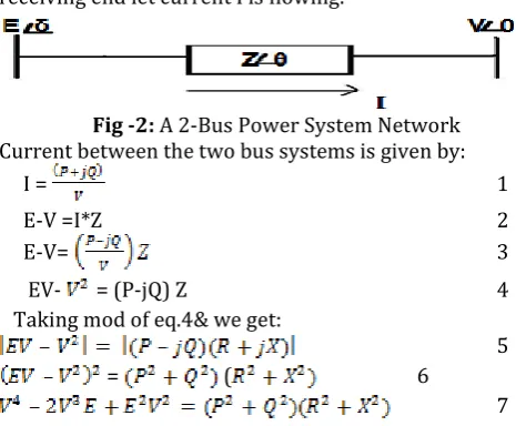
Fig. 1 represents a power system network with two buses. Let us assume that E is the sending end voltage is E and the V is receiving end voltage is V, delta is the phase difference between sending and receiving end voltages and impedance of the system is Z. From Sending end to receiving end let current I is flowing.
Fig -2: A 2-Bus Power System Network Current between the two bus systems is given by:
I = 1
E-V =I*Z 2
E-V= 3
EV- = (P-jQ) Z 4
Taking mod of eq.4& we get:
5
= ( 6
7
Assume P is the Active power flowing between two buses and Q is the Reactive Power flowing in the line. The value of Active Power P and Imaginary Power Q can be evaluated from equation 1 and 7.
On applying equation 1 in equation 7 we get,
8
V= 9
© 2015, IRJET.NET- All Rights Reserved
Page 323
P = 10
Q = - 11
5. Reactive Power
To express the background energy movement in an Alternating Current (AC) system arising from the production of electric and magnetic fields Imaginary power concept is used by engineers. Electric and Magnetic fields store energy which changes through each AC cycle. The devices which can store energy by magnetic field produced by a flow of current can absorb reactive power like inductor L. The devices which store energy by electric fields can generate reactive power e.g. Capacitor C.
To prevent voltage collapse power system have to operate within acceptable voltage limits i.e. between marginal limits, the power flows must be carefully controlled for a power system network. The flow of imaginary power gives rise to substantial change in voltage across the system i.e. it is very essential to create a reactive power balances between sources of generation and points of demand. Voltages at points across the system form a "voltage profile" which is related to local generation and demand at that instant, and is affected by the system network arrangements, unlike system frequency, which is same throughout an interconnected system,. To secure the transmission network National Grid has a defined voltage and stability criteria. By through circuit arrangements, transformers and shunt or static compensation we can achieve this.
5.1 Importance of Reactive power:
-For stable operation of power equipments Voltage control of electrical power system is very essential. This will prevent the damage like overheating of motors and generator, It reduces the transmission losses and maintain the ability of the system to withstand and prevent voltage unbalance or blackout. When reactive power increases then voltage of the system rises while if reactive power decreases then it causing voltage to fall. A voltage collapse will occurs in the system when the system to serve much more load than the voltage can support.
When imaginary power supply reduced voltage, as voltage decreases current will increase to maintain the power supplied, this will causes the system to consume more imaginary power and due to this voltage further reduces. If the current rises too much than the transmission lines go off line this may overload other lines as well and causes potentially cascading failures. To protect themselves when the voltage of system drops too low generators will disconnect automatically. When increase in load or less power generation or power transmission in the system the voltage collapse may occurs, this may causes a further reduction in imaginary power. If the decrease in voltage
continues, then due to this additional elements may trip, which leads further reduction in voltage. If the system is unable to provide required reactive power demands then this will result in entire progressive and uncontrollable declines in voltage.
5.1 Methods of Improving Voltage Stability: -
1. SHUNT CAPACITORS 2. SERIES CAPACITORS
3. SYNCHRONOUS CONDENSERS 4. SVC
5. STATCOM
6. Load flow analysis
Power system analysis or load flow analysis is very important for a system with multiple load centers. The capability of system to continuously supply the connected load is called Load flow Analysis.
By powers system analysis individual line losses and total losses, as well as are computed. At critical locations like motor control centers, to insure voltage we can determine the transformer tap positions. On an existing power
system performing load flow analysis gives
recommendations to the system operation and
optimization of control settings to acquire maximum capacity while reducing the operating costs. The value of Real Power P, Imaginary power Q, Voltage Magnitude V and Phase Angle for all buses in the power system can be evaluated from this analysis.
6.1 Techniques of Load flow analysis: -
There are
three methods of power flow analysis:1. Newton-Raphson Method (N-R)
2. Gauss-Seidel Method (G-S)
3. Fast-Decoupled Method
For solving non-linear equations Newton-Raphson method is an important technique. This is very fast method and it converges fast compared to the Gauss-Seidel method. N-R method is very practical technique for power flow solution of large power system network. The disadvantage of N-R technique is that it requires large computer memory which has been overcome through a compact storage scheme.
In our paper we have applied NR technique for analyzing an interconnected power system network.
© 2015, IRJET.NET- All Rights Reserved
Page 324
The set of non-linear equations can be solved byNewton-Raphson technique. Here we are presenting the method of solving non-linear equations using N-R.
Let us asume that we have n set of nonlinear equations with n total number of variables x1, x2, , xn.
Let n non-linear equations be given by,
Now the variables will become,
corrected variables of equation14 as given by,
Equation 15 can be expanded using Taylor’s series around the nominal initial values of the variables x1(0), x2(0), ,xn(0). Second and higher order terms of the series an be
neglected, the expansion of function gk, k = 1, , n is
written as,
0 0We can write equation (16) in the vector-matrix form as,
The solution of equation17 is,
After iteration 1st we will have,
ng number of P-V (generator) buses, such that,
n = np + ng + 1
Assume that slack bus is Bus-1. The method to Newton-Raphson technique is same as solving a system of nonlinear equations using the N-R method, we have to form a Jacobian Matrix after each iteration. And then solving this Jacobian for the corrections from an equation of the type given in equation(17).
© 2015, IRJET.NET- All Rights Reserved
Page 325
The sub matrices are
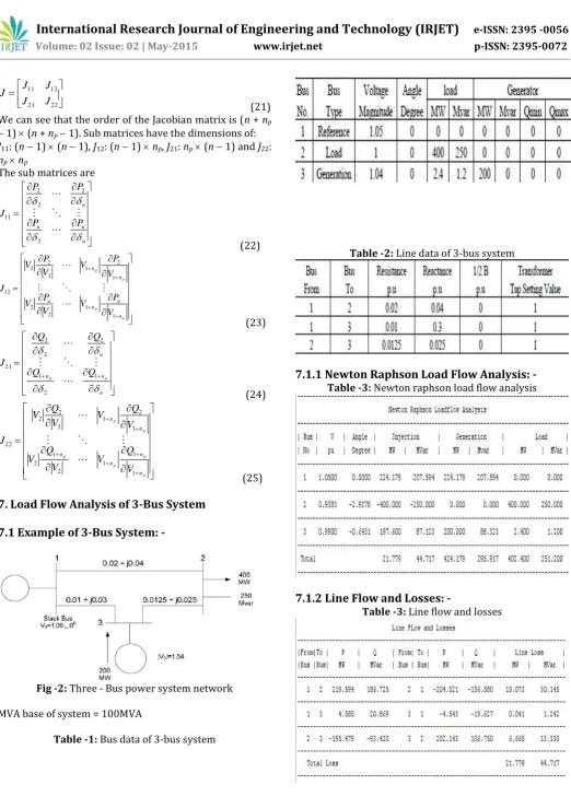
7. Load Flow Analysis of 3-Bus System
7.1 Example of 3-Bus System: -
Fig -2: Three - Bus power system network
MVA base of system = 100MVA
Table -1: Bus data of 3-bus system
Table -2: Line data of 3-bus system
7.1.1 Newton Raphson Load Flow Analysis: -
Table -3: Newton raphson load flow analysis
7.1.2 Line Flow and Losses: -
© 2015, IRJET.NET- All Rights Reserved
Page 326
7.2 Voltage Stability Analysis: -
The criteria of voltage stability is(26)
To retain its voltage stability, magnitude of expression
[ ] must be less than unity. Thus is the voltage
stability indicator. Sr = complex power Yll = self admittance of bus V = voltage
Table -5: voltage stability analysis
8.
CONCLUSIONS
Power-flow or load-flow analysis is important for planning future expansion of power systems as well as in determining the best operation of existing systems. The main information obtained from the power-flow analysis is the real and reactive power flowing in each line, magnitude and phase angle of the voltage at each bus. Newton-Raphson method is the best method for power-flow analysis, because it works faster and is sure to convergence in most cases as compared to the Gauss-Seidel method. It is an important practical method of load flow solution of large power system networks. After this load flow analysis we have evaluated the voltage stability at each bus of the power system. Voltage Stability is
determined by the indicator expression. The
magnitude of this voltage stability indicator expression [ ] must be less than unity.
REFERENCES
[1]. C.W. Taylor. Power System Voltage Stability. McGraw-Hill, New York, 1994.
[2]. V. Borozan, M.E. Baran and D. Novosel, “Integrated Volt/Var Control in Distribution Systems”, in Proc. of IEEE Power Engineering Society Winter Meeting, 2001.
[3]. ChakrabartiA, Kothari D P and Mukhopadhyay , Performance, Operation and control of EHV Power Transmission Systems, I st ed, New Delhi Wheeler ch no 6 pp 132 -141. 2000.
[4]. Wadhawa C.L. Electrical Power System V ed New Age International (P) Limited Publishers, New Delhi.ch no 10 pp no 226-228 2009.
[5]. Mark N Nwohu “Voltage Stability Improvement using Static Var Compensator in Power Systems” Leonardo Journal of Sciences ISSN pp1583-0233., January – June 2009.
[6]. “IEEE Recommended Practice for Excitation System Models for Power System Stability Studies‟‟, IEEE Power Engineering Society, New York, April 2006. [7]. K. Vu: “Use of local measurements to estimate voltage