MAP Estimation of Chin and Cheek Contours
in Video Sequences
Markus Kampmann
Ericsson Research, Ericsson Allee 1, 52134 Herzogenrath, Germany Email:[email protected]
Received 28 December 2002; Revised 8 September 2003
An algorithm for the estimation of chin and cheek contours in video sequences is proposed. This algorithm exploits a priori knowledge about shape and position of chin and cheek contours in images. Exploiting knowledge about the shape, a parametric 2D model representing chin and cheek contours is introduced. Exploiting knowledge about the position, a MAP estimator is developed taking into account the observed luminance gradient as well as a priori probabilities of chin and cheek contours posi-tions. The proposed algorithm was tested with head and shoulder video sequences (image resolution CIF). In nearly 70% of all investigated video frames, a subjectively error free estimation could be achieved. The 2D estimate error is measured as on average between 2.4 and 2.9 pel.
Keywords and phrases:facial feature extraction, model-based video coding, parametric 2D model, face contour, face model.
1. INTRODUCTION
Techniques for estimation of facial features like eyes, mouth, nose, eyebrows, chin and cheek contours are essential for var-ious types of applications [1,2,3,4,5,6,7,8]. For facial recognition applications, features are estimated and used for recognition, authentification, and differentiation of human faces [7,9,10]. In multimedia data bases and information systems, facial feature estimation is required for analysis and indexing of human facial images. For specific video coding schemes like model-based video coding [11, 12, 13] (also sometimes called semantic video coding [14,15] or object-based video coding [16,17,18]), facial feature estimation is also required. The estimated facial features are used for adap-tation of a 3D face model to a person’s face as well as for the determination of facial expressions [19,20,21,22,23].
In this paper, the estimation of chin and cheek contours is discussed. The estimation of chin and cheek is one of the most difficult tasks of facial feature estimation, especially that the chin contour is in many cases little visible. Furthermore, shadows, variations of the skin color, clothing, and double chin can complicate the estimation procedure. Rotations of the head (especially to the side) result in strong variations of the chin and cheek’s shape and position. In this paper, head and shoulder video sequences are considered which are typi-cal for news, videophone, or video conferencing sequences. Assuming a typical spatial resolution like the CIF format (352×288 luminance pels), the face size is quite small in those video sequences (with a typical face width from 40 to
70 pels). Taken this into account, the estimation of chin and cheek contours is further complicated.
In order to overcome these problems of chin and cheek contours estimation, the usage of a priori knowledge about these features is necessary. On one hand, knowledge about the typical shape of chin and cheek contours should be ex-ploited. On the other hand, knowledge about more or less probable positions of chin and cheek contours should be taken into consideration.
are used for the estimation of chin and cheek contours. A
snake is an energy-minimizing spline influenced by image
features to pull it toward edges. These approaches were ap-plied to persons looking straight into the camera. Since the number of unknown parameters is high, the reliability of these algorithms is low [27].
In this paper, a new algorithm for chin and cheek con-tours’ estimation is proposed. A priori knowledge about the typical shape and probable positions of chin and cheek contours is exploited in many ways. A new parametric 2D model representing chin and cheek contours is introduced. This 2D model consists of four parabola pieces which are linked together. The 2D model is described by eight param-eters which have to be estimated. Assuming video sequences with a quite small face size, this model allows an exact lo-calization of chin and cheek contours with a low number of parameters to be estimated. For estimation, a MAP es-timator is developed. This eses-timator takes into account the observed luminance gradient as well as the probabilities of certain positions of chin and cheek contours. Besides, ro-tations of the head are also considered in the new estima-tor. For estimation, the positions of eyes and mouth are assumed to be known. In this paper, the algorithm from [20] is used for estimation of eyes and mouth middle po-sitions.
The paper is organized as follows. InSection 2, the new parametric 2D model for chin and cheek contours is intro-duced. InSection 3, the chin contour is estimated, whereas the cheek contour is estimated inSection 4.Section 5gives experimental results. A conclusion is given inSection 6.
2. PARAMETRIC 2D MODEL OF CHIN
AND CHEEK CONTOURS
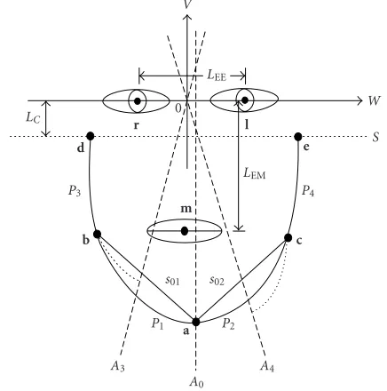
For representing the shape of chin and cheek contours, a parametric 2D model for these contours is introduced. The estimation of chin and cheek contours is done by estima-tion of the parameters of this 2D model.Figure 1shows the parametric 2D model in a local, 2D system of coordinates (W,V). The origin of (W,V) lies in the middle of the inter-section between the eyes middle pointsrandl. TheW axis shows in the direction of the left eye middle pointl. The 2D model consists of the four parts of a parabolaP1,P2,P3, and
P4 which are linked together.P1 andP2 represent the chin
contour, whileP3andP4the cheek contours. The endpoints
a=(aW,aV)T andb=(bW,bV)T form the boundary ofP1,
while the endpointsa=(aW,aV)T andc=(cW,cV)T form
the boundary of P2. A parabola part is unambiguously
de-scribed by its two endpoints and the parabola axis. For the chin contour, the parabola axisA0is defined in such a way
thatA0is parallel to theV axis andais a part ofA0.
There-fore, P1 andP2 are completely described by the three
end-pointsa = (aW,aV)T,b = (bW,bV)T, and c = (cW,cV)T
only. So, six parameters have to be determined for the esti-mation of the chin contour.
The right cheek contour is described by the parabola pieceP3. The endpointsb=(bW,bV)T andd =(dW,dV)T
LC r l
W
S V
LEE
LEM 0
d e
c b
a m
s01 s02
P1 P2
P3 P4
A3 A4
A0
Figure1: Parametric 2D model of chin and cheek contours con-sisting of four parabola piecesP1,P2,P3, andP4.randlare the eyes middle points, andmthe mouth middle point.
form the boundary ofP3. For a complete description ofP3,
its parabola axisA3 is needed.A3 can be constructed from
the parameters of the chin contour. A3is defined in such a
way that it passes the origin of (W,V) and divides chords01
betweenaandbin the middle. Since the endpointsaandb are known after the chin contour estimation, only the posi-tiond = (dW,dV)T is unknown for a complete description
ofP3.ddepends on another restriction. Cheek contours are
often covered by hair and therefore impossible to estimate. So, dis defined in such a way that it passes the lineS.Sis parallel to the W axis with a distanceLC. LC is chosen as
LC = 0.15LEMwith the eye-mouth distanceLEM defined as
the distance between theWaxis and the mouth middle point m. So, only theW-coordinatedW is necessary for a
descrip-tion ofd. Corresponding toP3, only theW-coordinateeWis
necessary for the description ofP4. Taken these two
param-eters for the cheek contours into account, eight paramparam-eters have to be estimated for the chin and cheek contours.
The estimation is carried out in two steps. First, the chin contour is estimated. Using the estimated chin contour, the cheek contours are estimated in a second step.
3. ESTIMATION OF CHIN CONTOUR
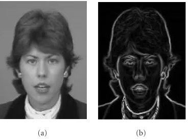
For estimation of the chin contour, the absolute value of the luminance gradient|g(W,V)|is computed using the Sobel operator (Figure 2).
|g(W,V)| is the observable measurement value that is used for estimation of the unknown parameters a = (aW,aV)T,b=(bW,bV)T, andc=(cW,cV)T. For
(a) (b)
Figure2: Luminance gradient: (a) luminance image; (b) absolute value of the luminance gradient determined by Sobel operator.
fchin = (aW,aV,bW,bV,cW,cV)T. For chin contour
estima-tion, an estimation algorithm is necessary which calculates an estimated value ˆfchin from the known absolute value of
the luminance gradient|g(W,V)|. Here, a MAP estimator is used. ˆfchinis calculated using the MAP estimation algorithm
according to
with g = |g(W,V)|. The conditional probability density function pg|fchin(g|fchin) is called likelihood function, while pfchin(fchin) is the a priori probability density function of the parameter vector fchin. The product from likelihood
func-tion and a priori probability density funcfunc-tion is called quality function. For calculation of ˆfchin, the quality function has to
be established first. Then, the quality function is maximized by an optimization algorithm and the estimate value ˆfchinis
determined.
The likelihood function pg|fchin(g|fchin) determines the probability for a measurement valueg under the condition of a certain positionfchinof the chin contour. The
determina-tion ofpg|fchin(g|fchin) is difficult since manifold disturbances like shadows, clothing, or skin variations influence the obser-vationg. Therefore, a simple approach is chosen in this work. Here, a proportional relation betweenpg|fchin(g|fchin) and the mean absolute value of the luminance value along the chin contour is assumed: nance gradient’s absolute value along the parabola piecesP1
andP2;LP1+P2is the length of both parabola pieces; andcchin a proportional constant.P1andP2are dependent on the
pa-rameters offchin. According to (2), a high value of the mean
luminance gradient corresponds to a high value of the likeli-hood functionpg|fchin(g|fchin). On the other hand, a low value means that the observed measurement belongs to the consid-ered parameter vector with a low probability.
pa p(aV)
aV,min aV,1 aV,2 aV,max
aV
Figure3: Probability densityp(aV).
The probability density function pfchin(fchin) describes the probability of a certain chin contour position fchin =
(aW,aV,bW,bV,cW,cV)T. Due to the human anatomy, the
bottom point a of the chin contour is located below the mouth and near the V axis. The W-coordinateaW varies
only slightly. The upper endpointsbandcare approximately located at the height of the mouth. The V coordinatesbV
andcVvary only little. Taking this into account, it is assumed
thatpfchin(fchin) is only dependent on the coordinatesaV,bW, and cW. Assuming a further independence betweenaV on
one side andbWandcWon the other side,pfchin(fchin) is equal
is set, whereasaV,minandaV,maxare set proportional to the
eye-mouth distanceLEM(seeFigure 1). In case of talking, the
mouth of a person is opened and closed. The position aV
is changing corresponding to the mouth movement. Due to the uniform movement, the probabilityp(aV) is not changed
inside most part of theaV range (Figure 3).
tional to the eye-mouth distanceLEM.
Next, the termp(bW,cW) in (3) is examined. First, ranges
forbW andcW are introduced which are symmetrical to the
V axis:−bW,max< bW <−bW,minandbW,min< cW < bW,max.
Here, bW,min,bW,max > 0 and are set proportional to the
eye-eye distanceLEE. SincebWandcW are hardly influenced
by the mouth movement, the assumption of a nearly uni-form probability distribution is in contrast to p(aV) not
useful. Considering instead that values of bW, cW have a
|bW|
|cW|
Figure4: In case of a head rotation to the left side, a low value of |cW|corresponds to a high value of|bW|.
In case of a statistical independence betweenbWandcW,
the probabilityp(bW,cW) could be expressed by
pbW,cW
For this case, a certain value ofcW would have no influence
on the occurrence of certain values ofbW. However,Figure 4
shows that a dependence betweenbWandcWexists.
In case of a head rotation to the left side,|cW|has a low
value. In this case,|bW|has a high value. Therefore, an
in-dependence betweenbW andcW does not exist. In order to
take their dependence into consideration, (6) is extended by an additional termpdep(bW,cW):
In case of a head rotation to the right side, a low value of |bW|corresponds to a high value of|cW|. Looking at the sum
Figure5:pdep(bW,cW) describes the dependence betweenbWand
cWby the distance of the chin contour|bW|+|cW|.
The upper boundsbc,maxand the lower boundsbc,minfor
the distance of the chin contour endpoints are set propor-tional to the eye-eye distanceLEE.
Using (2), (4), and (7), the quality function in (1) is com-pletely known. The next step is the maximization of (1) and the determination of ˆfchin. The optimization is carried out in
two steps. First, an initial value ˆfchin,initis determined. Using
ˆ
fchin,init, the final value ˆfchinis determined in the second step.
In the first step, search lines S0,S1, andS2 are introduced
(Figure 6). The initial values for the chin contour endpoints should be located on these lines. The lower search line S0
forais located on theV axis and is bounded byaV,minand
aV,max, respectively. The search linesS1andS2forbandcare
on the height of the mouth middle point and parallel to the W axis. They are bounded by−bW,max,−bW,minandbW,min,
bW,max, respectively. Along these search lines, local maxima
of|g(W,V)|are determined. Only these local maxima could be the initial values fora,b, andc. For all combinations of these local maxima, the quality function in (1) is evaluated. The combination with the highest value of the quality func-tion is chosen as initial estimate value ˆfchin,init. Taking ˆfchin,init
as a starting point, the final value ˆfchin is determined in the
following second step. 2D search areas are placed around the chin contour endpoints belonging to ˆfchin,init. Inside these
search areas, the optimization is continued. Starting from the endpoints belonging to ˆfchin,init, the quality function in (1)
is evaluated in an 8-point neighborhood around these end-points. If the quality function is improved inside the 8-point neighborhood, the corresponding point is chosen as center for the next 8-point neighborhood evaluation. This proce-dure is continued until no more improvement of the quality function can be achieved. Then, the final estimate value ˆfchin
is found. The estimation of the chin contour is completed.
4. ESTIMATION OF CHEEK CONTOURS
Next, the cheek contours are estimated. The cheek contours are completely described by the parameter vector fcheek =
S1 S2
S0
Figure6: Search lines for initial estimation of the chin contour.
carried out analogous to the chin contour estimation. Ac-cording to (1), a MAP estimator imated by the integral over the absolute value of the lumi-nance gradient along the parabola piecesP3andP4:
pg|fcheek
whereLP3+P4denotes the length of both parabola pieces and ccheeka proportional constant.pfcheek(fcheek) is described by
pfcheek
to the eye-eye distanceLEE. For determination of ˆfcheek, the
search linesS3,S4are introduced which are located on the
lineS(see Figure 1) and are bounded by−dW,max,−dW,min
Table1: Upper and lower bounds for chin and cheek parameters.
LEEdenotes the distance between the eyes middle points, whileLEM denotes the distance between eyes and mouth.
Bound Scale Value
anddW,min,dW,max, respectively. Along these search lines,
lo-cal maxima of |g(W,V)|are determined. Only these local maxima could be estimate values fordW,eW. For all
combi-nations of these local maxima, the quality function in (10) is evaluated. The combination with the highest value of the quality function is the estimate value ˆfcheek. So, the estimation
of the cheek contours is completed.
5. EXPERIMENTAL RESULTS
First, experiments were carried out in order to verify the as-sumed a priori probability density functions from Sections3
and4. Furthermore, upper and lower bounds for the proba-bility density functions are determined.
In the second part, the proposed algorithm for chin and cheek contours estimation is tested with head and shoulder videophone sequences and its performance is evaluated.
5.1. Verification
For verification of the a priori probability density functions as well as for determination of the corresponding upper and lower bounds, tests were carried out. Here, 60 facial images (30 female and 30 male faces) from an image database were selected. The true positions of eyes and mouth mid-dle positions and chin and cheek contours were manually determined from the facial images, and the parametersaV,
bW,cW,dW,eW,|bW|+|cW|, and|dW|+|eW|were
calcu-lated. First, the upper and lower boundsaV,min,aV,max,aV,1,
aV,2, bW,min, bW,max, dW,min, dW,max, sbc,min, sbc,max, sde,min,
andsde,maxwere determined. As described in Sections3and 4,aV,min,aV,max,aV,1, andaV,2 are set proportional to the
eye-mouth distanceLEMandbW,min,bW,max,dW,min,dW,max,
sbc,min,sbc,max,sde,min, andsde,maxare set proportional to the
eye-eye distance LEE.Table 1 shows the determined values
0 2 4 6 8 10 12 14
Figure7: Frequency distribution for chin tipaV. The value range (aV,min,aV,max) is subdivided into ten parts. For each part, the fre-quency out of 60 facial images is determined.
0 2 4 6 8 10 12 14
Figure8: Frequency distribution for right chin contour endpoint
bW. The value range (bW,min,bW,max) is subdivided into ten parts. For each part, the frequency out of 60 facial images is determined.
0 2 4 6 8 10 12 14 16 18 20
Figure9: Frequency distribution for left chin contour endpointcW. The value range (bW,min,bW,max) is subdivided into ten parts. For each part, the frequency out of 60 facial images is determined.
These values are used for the next step, the verifica-tion of the assumed a priori probability density funcverifica-tions from Sections3and4. For all parametersaV,bW,cW,dW,
eW,|bW|+|cW|, and |dW|+|eW|, the corresponding
fre-quency distribution using the 60 facial test images is cal-culated. Therefore, each parameter range is divided into 10 parts between its lower and upper bounds. For each part, the corresponding frequency of the parameter value within this part is determined. Figures7,8,9,10,11,12, and13show the results. For the chin tip position aV, a uniform
distri-bution was assumed inSection 3. For the other parameters, sinus-like distributions with more significant decreases to-wards the bounds were assumed. Looking at the frequency
0 2 4 6 8 10 12 14 16 18 20
Figure10: Frequency distribution for right cheek contour endpoint
dW. The value range (dW,min,dW,max) is subdivided into ten parts. For each part, the frequency out of 60 facial images is determined.
0 2 4 6 8 10 12 14 16 18
Figure11: Frequency distribution for left cheek contour endpoint
eW. The value range (dW,min,dW,max) is subdivided into ten parts. For each part, the frequency out of 60 facial images is determined.
0 2 4 6 8 10 12 14 16
Figure12: Frequency distribution for|bW|+|cW|(distance between chin contour endpoints). The value range (sbc,min,sbc,max) is subdi-vided into ten parts. For each part, the frequency out of 60 facial images is determined.
0 2 4 6 8 10 12 14
(a) (b) (c) Figure14: Test sequences: (a) Akiyo, (b) Miss America, and (c) Claire.
distributions from Figures7,8,9,10,11,12, and13, these assumptions are verified in general. WhereasFigure 7shows a more uniform distribution, the other figures show signifi-cant decreases towards the bounds.
However, further experiments with a larger number of facial test images should be carried out in the future in or-der to further check the assumed a priori probability density functions and the parameters’ upper and lower bounds.
5.2. Performance evaluation
For evaluation of the proposed algorithm, the head and shoulder video sequences Akiyo, Claire, and Miss America
with a resolution corresponding to CIF (352×288 luminance pels) and a frame rate of 10 Hz were used to test its perfor-mance (Figure 14). For the sequence Miss America, the per-son is mainly looking into the camera. For Claire, head rota-tion to the sides are observed. For Akiyo, the person is often looking down.
For evaluation of the algorithm’s accuracy, the true po-sitions of chin and cheek contours are manually determined from the video sequences. These true positions are then com-pared with the estimated ones to get the 2D estimate er-ror in the image. Table 2 shows the estimate error’s stan-dard deviation for the test sequences. Here, it is distinguished between the chin tip a, the chin contour’s upper points b,c, and the cheek contour’s upper points d, e. Looking at the results, the estimate error for chin contour’s upper pointsb,c, and cheek contour’s upper pointsd,eare quite similar: 2.4 pel and 2.5 pel, respectively. The estimate error for the chin tip a is 2.9 pel, which is larger compared to the other four endpoints. The reason for this is mainly the video sequence Miss America, where the chin contour is very weak, disturbed by a shadow, and therefore difficult to esti-mate.
For additional evaluation, the estimation results are sub-jectively rated. In contrast to the results above, not only the positions of the five parabola pieces’ endpoints are evaluated. Instead, the estimate of the complete chin and cheek con-tours is compared with the true ones. Three different subjec-tive quality classes are introduced. In the first class, no de-viation between the true and the estimated chin and cheek contours is observable, the estimation is error free. For the second quality class, an estimation error is observable.
Fi-Table2: Standard deviation of 2D estimate errors for the chin and cheek contours (video sequences Akiyo, Claire, and Miss America).
Facial feature point 2D estimate error (pel)
Chin tipa 2.9
Chin contour’s upper pointsb,c 2.4 Cheek contour’s upper pointsd,e 2.5
Table3: Percentage of estimated chin and cheek contours accord-ing to three quality classes (video sequences Akiyo, Claire, and Miss America).
Quality classes Percentage (%)
(1) Error free 68
(2) Estimation error observable 32
(3) Complete mismatch 0
nally, the third class means erroneous results, where the true contours are completely missed. For example, hair, clothing, lips, and so forth are detected instead of chin and cheek. All estimated chin and cheek contours are rated according to the three quality classes.Table 3 shows the achieved results. In nearly 70% of all frames, an error free estimation is possible. A completely missed estimation was observed in no frame.
Figures15,16,17, and18show examples of the estimated chin and cheek contours over the original images. Figures
15,16, and17shows results of the first quality class with er-ror free estimation. Results from the second quality class are given inFigure 18. Here, small deviations are noticed.
Since an accurate estimate of eyes and mouth middle po-sitions is fundamental for the proposed chin and cheek es-timation, an evaluation of the used algorithm from [20] for eyes and mouth estimation is given. Figures15,16,17, and
Figure15: Test sequence Akiyo: estimated chin and cheek contours over original images without estimation error (quality class 1). Displayed eyes and mouth middle positions are estimated by [20] and are known to the algorithm.
Figure16: Test sequence Claire: estimated chin and cheek contours over original images without estimation error (quality class 1). Displayed eyes and mouth middle positions are estimated by [20] and are known to the algorithm.
6. CONCLUSIONS
A new algorithm for estimation of chin and cheek contours in video sequences is proposed. Within this algorithm, a pri-ori knowledge about shape and position of chin and cheek contours is exploited. A parametric 2D model representing the shape of chin and cheek contours is introduced. This 2D model consists of four parabola pieces which are linked to-gether. Eight parameters describe the parametric 2D model.
Figure17: Test sequence Miss America: estimated chin and cheek contours over original images without estimation error (quality class 1). Displayed eyes and mouth middle positions are estimated by [20] and are known to the algorithm.
Figure18: Test sequences Akiyo, Claire, Miss America: estimated chin and cheek contours over original images with observable esti-mation errors (quality class 2). Displayed eyes and mouth middle positions are estimated by [20] and are known to the algorithm.
Using facial images from an image data base, the assumed a priori probabilities of the chin and cheek contours’ posi-tions were verified. Then, the proposed algorithm was tested with typical head and shoulders video sequences. In nearly 70% of all frames, a subjectively perfect estimation is pos-sible. In no frame, a complete mismatch is noticeable. The standard deviation of the 2D estimate error is measured as 2.4 pel (upper endpoints of the chin contour), 2.5 pel (up-per endpoints of the cheek contours), and 2.9 pel (chin tip), respectively.
A further advantage of the described algorithm is its flibility. The assumed a priori probabilities could be easily ex-changed by other functions if further measurements will sug-gest this.
ACKNOWLEDGMENT
This work has been carried out at the Institute of Commu-nication Theory and Signal Processing, University of Han-nover, Germany.
REFERENCES
[1] P. M. Antoszczyszyn, J. M. Hannah, and P. M. Grant, “Facial features motion analysis for wire-frame tracking in model-based moving image coding,” inProc. IEEE International Con-ference on Acoustics, Speech, and Signal Processing, vol. 4, pp. 2669–2672, Munich, Germany, April 1997.
[2] G. Chow and X. Li, “Towards a system for automatic facial feature detection,” Pattern Recognition, vol. 26, no. 12, pp. 1739–1755, 1993.
[4] S.-H. Jeng, H. Y. M. Liao, C. C. Han, M. Y. Chern, and Y. T. Liu, “Facial feature detection using geometrical face model: an efficient approach,”Pattern Recognition, vol. 31, no. 3, pp. 273–282, 1998.
[5] C. J. Kuo, R.-S. Huang, and T.-G. Lin, “3-D facial model esti-mation from single front-view facial image,”IEEE Trans. Cir-cuits and Systems for Video Technology, vol. 12, no. 3, pp. 183– 192, 2002.
[6] M. J. T. Reinders, F. A. Odijk, J. C. A. van der Lubbe, and J. J. Gerbrands, “Tracking of global motion and facial expressions of a human face in image sequences,” inProc. SPIE Visual Communications and Image Processing, vol. 2904, pp. 1516– 1527, Boston, Mass, USA, November 1993.
[7] A. Samal and P. Iyengar, “Automatic recognition and analy-sis of human faces and facial expressions: a survey,” Pattern Recognition, vol. 25, no. 1, pp. 65–77, 1992.
[8] A. Yuille, P. Hallinan, and D. Cohen, “Feature extraction from faces using deformable templates,” International Journal of Computer Vision, vol. 8, no. 2, pp. 99–111, 1992.
[9] R. Brunelli and T. Poggio, “Face recognition: features versus templates,” IEEE Trans. on Pattern Analysis and Machine In-telligence, vol. 15, no. 10, pp. 1042–1052, 1993.
[10] R. Chellappa, C. L. Wilson, and S. Sirohey, “Human and ma-chine recognition of faces: a survey,” Proceedings of the IEEE, vol. 83, no. 5, pp. 705–741, 1995.
[11] K. Aizawa and T. S. Huang, “Model-based image coding ad-vanced video coding techniques for very low bit-rate applica-tions,” Proceedings of the IEEE, vol. 83, no. 2, pp. 259–271, 1995.
[12] C. S. Choi, K. Aizawa, H. Harashima, and T. Takebe, “Analysis and synthesis of facial image sequences in model-based image coding,” IEEE Trans. Circuits and Systems for Video Technol-ogy, vol. 4, no. 3, pp. 257–275, 1994.
[13] W. J. Welsh, S. Searby, and J. B. Waite, “Model-based image coding,” British Telecom Technology Journal, vol. 8, no. 3, pp. 94–106, 1990.
[14] H. Musmann, “A layered coding system for very low bit rate video coding,” Signal Processing: Image Communication, vol. 7, no. 4–6, pp. 267–278, 1995.
[15] L. Zhang, “Automatic adaptation of a face model using action units for semantic coding of videophone sequences,” IEEE Trans. Circuits and Systems for Video Technology, vol. 8, no. 6, pp. 781–795, 1998.
[16] M. Kampmann and J. Ostermann, “Automatic adaptation of a face model in a layered coder with an object-based analysis-synthesis layer and a knowledge-based layer,” Signal Process-ing: Image Communication, vol. 9, no. 3, pp. 201–220, 1997. [17] H. Musmann, M. H¨otter, and J. Ostermann, “Object-oriented
analysis-synthesis coding of moving images,” Signal Process-ing: Image Communication, vol. 1, no. 2, pp. 117–138, 1989. [18] J. Ostermann, “Object-based analysis-synthesis coding based
on the source model of moving rigid 3D objects,” Signal Processing: Image Communication, vol. 6, no. 2, pp. 143–161, 1994.
[19] P. M. Antoszczyszyn, J. M. Hannah, and P. M. Grant, “A com-parison of detailed automatic wire-frame fitting methods,” in Proc. IEEE International Conference on Image Processing, vol. 1, pp. 468–471, Santa Barbara, Calif, USA, October 1997. [20] M. Kampmann, “Automatic 3-D face model adaptation
for model-based coding of videophone sequences,” IEEE Trans. Circuits and Systems for Video Technology, vol. 12, no. 3, pp. 172–182, 2002.
[21] M. J. T. Reinders, P. J. L. van Beek, B. Sankur, and J. C. van der Lubbe, “Facial feature location and adaptation of a generic face model for model-based coding,”Signal Processing: Image Communication, vol. 7, no. 1, pp. 57–74, 1995.
[22] R. L. Rudianto and K. N. Ngan, “Automatic 3D wireframe model fitting to frontal facial image in model-based video coding,” in Proc. International Picture Coding Symposium (PCS ’96), pp. 585–588, Melbourne, Australia, March 1996. [23] Z. Wen, M. T. Chan, and T. S. Huang, “Face animation driven
by contour-based visual tracking,” inProc. International Pic-ture Coding Symposium (PCS ’01), pp. 263–266, Seoul, Korea, April 2001.
[24] H.-J. Lee, D.-G. Sim, and R.-H. Park, “Relaxation algorithm for detection of face outline and eye locations,” in Proc. IAPR Workshop on Machine Vision Applications, pp. 527–530, Makuhari, Chiba, Japan, November 1998.
[25] E. Saber and A. M. Tekalp, “Frontal-view face detection and facial feature extraction using color, shape and symme-try based cost functions,” Pattern Recognition Letters, vol. 19, no. 8, pp. 669–680, 1998.
[26] K. Sobottka and I. Pitas, “A novel method for automatic face segmentation, facial feature extraction and tracking,” Signal Processing: Image Communication, vol. 12, no. 3, pp. 263–281, 1998.
[27] C.-L. Huang and C.-W. Chen, “Human facial feature extrac-tion for face interpretaextrac-tion and recogniextrac-tion,”Pattern Recogni-tion, vol. 25, no. 12, pp. 1435–1444, 1992.
Markus Kampmann was born in Essen, Germany, in 1968. He received the Diploma degree in electrical engineering from the University of Bochum, Germany, in 1993, and the Doctoral degree in electrical engi-neering from the University of Hannover, Germany, in 2002. From 1993 to 2001, he was working as a Research Assistant at the Institute of Communication Theory and Signal Processing, the University of