R E S E A R C H
Open Access
Interference tables: a useful model for
interference analysis in asynchronous
multicarrier transmission
Yahia Medjahdi
1*, Michel Terré
2, Didier Le Ruyet
2and Daniel Roviras
2Abstract
In this paper, we investigate the impact of timing asynchronism on the performance of multicarrier techniques in a spectrum coexistence context. Two multicarrier schemes are considered: cyclic prefix-based orthogonal frequency division multiplexing (CP-OFDM) with a rectangular pulse shape and filter bank-based multicarrier (FBMC) with physical layer for dynamic spectrum access and cognitive radio (PHYDYAS) and isotropic orthogonal transform algorithm (IOTA) waveforms. First, we present the general concept of the so-called power spectral density
(PSD)-based interference tables which are commonly used for multicarrier interference characterization in spectrum sharing context. After highlighting the limits of this approach, we propose a new family of interference tables called ‘instantaneous interference tables’. The proposed tables give the interference power caused by a given interfering subcarrier on a victim one, not only as a function of the spectral distance separating both subcarriers but also with respect to the timing misalignment between the subcarrier holders. In contrast to the PSD-based interference tables, the accuracy of the proposed tables has been validated through different simulation results. Furthermore, due to the better frequency localization of both PHYDYAS and IOTA waveforms, FBMC technique is demonstrated to be more robust to timing asynchronism compared to OFDM one. Such a result makes FBMC a potential candidate for the physical layer of future cognitive radio systems.
Keywords: PSD; Interference table; Time asynchronism; OFDM; FBMC; PHYDYAS; IOTA; Spectrum coexistence
1 Introduction
Nowadays, we witness a continuous evolution of applica-tions for wireless communicaapplica-tions requiring higher and higher spectral resources. In order to overcome the prob-lem of spectrum scarcity resulting from conventional static spectrum allocation, there is a growing interest in the design and the development of cognitive radio tech-nology [1]. The concept of cognitive radio is based on opportunistic access to the available frequency resources. It offers to future communication systems the ability to dynamically and locally adapt their operating spectrum by selecting it from a wide range of possible frequencies.
Multicarrier techniques are promising and potential candidates offering flexible access to these new spectrum opportunities [2]. Indeed, orthogonal frequency division
*Correspondence: [email protected]
1ICTEAM, Université catholique de Louvain, Place du Levant, 2, Louvain-la-Neuve 1348, Belgium
Full list of author information is available at the end of the article
multiplexing (OFDM), which is the most commonly used multicarrier technique, has been adopted in IEEE 802.22 standard for unlicensed wireless regional area network (WRAN) using cognitive communications on the unused TV bands [3]. Unfortunately, OFDM presents some weak-nesses. In fact, the redundancy, caused by the insertion of the cyclic prefix mandatory part of the transmitted OFDM symbol, reduces the useful data rate. Further-more, it has a limited frequency resolution due to the large sidelobes generated by the rectangular pulse shape frequency response. These shortcomings have stimulated the research for an alternative scheme that can overcome these problems.
In the last few years, a number of papers, e.g., [4-7] have focused on an enhanced physical layer based on the filter bank processing called filter bank-based multi-carrier (FBMC) technique which can offer a number of advantages compared to CP-OFDM systems such as the
improved spectral efficiency by not using a redundant CP and by having much better control of out-of-band emission, thanks to the time-frequency localized shaping pulses [8,9]. In the literature, we find two typical wave-forms that are used in filter bank systems: the isotropic orthogonal transform algorithm (IOTA) [10] and the ref-erence physical layer for dynamic spectrum access and cognitive radio (PHYDYAS) [11] prototype filter [12].
However, due to various factors, e.g., the propaga-tion delays and the spatial distribupropaga-tion of users, timing asynchronism is considered as one of the most chal-lenging issues in spectrum coexistence contexts. Indeed, the timing asynchronism between coexisting systems can harmfully affect the performance by causing the so-called asynchronous interference. Consequently, it is relevant to evaluate the impact of this asynchronism on the system performance.
Interference modeling is an important problem, with numerous applications to the analysis and design of mul-tiuser communication systems, as well as the development of interference mitigation techniques. This problem has been intensively investigated in the literature through the most common approach using the power spec-tral density (PSD) [8,9,13,14]. This model is based on the out-of-band radiation which is determined by the PSD model of multicarrier signals. However, this model does not always give accurate results. For exam-ple, in multiuser CP-OFDM when the timing offset does not exceed the cyclic prefix duration, the inter-ference comes only from the same subchannel and the other subchannels do not contribute to this interfer-ence. Unfortunately, in this case, the PSD modeling still shows that the other carriers contribute in the resulting interference.
It is worth mentioning that there are already several works in the literature showing the FBMC robustness to time asynchronism. In [15-17], the authors demonstrate that in an asynchronous multi-user scenario, FBMC sys-tems are more robust than OFDM syssys-tems to time and frequency misalignments among the users. Moreover, the sensitivity of the different FBMC waveforms is inves-tigated in [18]. However, we want to indicate that the interference modeling proposed in this paper is general and can be used for any multicarrier scheme. Moreover, this model is a more efficient alternative to overcome the limitations of the PSD-based modeling which is com-monly used in the analysis of interference in coexistence contexts.
In this paper, the impact of timing asynchronism on the performance of OFDM and FBMC systems is addressed. As a matter of fact, we would like to:
• Properly estimate the interference part introduced by the timing asynchronism for OFDM systems.
• Propose an extension of this model to the FBMC case, as it has, to our knowledge, never been considered in the literature.
• Extend the interference analysis to the case of frequency selective environments.
• Evaluate the accuracy of the proposed model through different simulation results.
The rest of this paper is organized as follows. Section 2 presents the general notion of the so-called interfer-ence tables, where we give the PSD-based interferinterfer-ence tables of CP-OFDM and FBMC considering PHYDYAS and IOTA prototype filters. In Section 3, we derive the OFDM/FBMC instantaneous interference tables taking into account the timing asynchronism in addition to the spectral distance between the interfering user and the vic-tim one. Next, we extend the interference analysis to the case of frequency selective environments in Section 4. The accuracy of the proposed interference modeling is then investigated in Section 5. We finally conclude the paper in Section 6.
1.1 Definitions and notations
In this paper, we are calculating interference weights that can be used in the estimation of interference in coexis-tence contexts. Since these weights are computed as a function of two parameters, the timing offset and the spectral distance between the coexisting systems, we then obtain a 2D table of these weights for each multicarrier scheme. Thus, we find it appropriate to call them ‘interfer-ence tables’. For simplicity sake, we also use this definition in the PSD-based approach.
2 The general concept of interference tables
Let us consider two asynchronous systems (A) and (B) that coexist in the same geographical area. We assume that both systems share a given frequency band whereFAand
FBare the frequency sub-bands occupied by systems (A) and (B), respectively.
Due to the non-orthogonality between their respective transmit signals, some amount of the power is spilled from a system to the other. In order to analyze this interaction, the PSD is generally used to evaluate the mutual interfer-ence between both systems [9,13]. According to [13], the normalized mutual interference between the co-located systems is defined as
I(l)=
(l+1/2)f
(l−1/2)f
(f)df, (1)
where:
• f is the subcarrier spacing.
• ( f)is the PSD which depends on the considered multicarrier technique.
In the case of CP-OFDM system, the normalized PSD is given in [13] by
OFDM(f)=TOFDM
sin(πfTOFDM)
πfTOFDM 2
, (2)
where TOFDM is the OFDM symbol duration given by
the sum of the useful symbol duration T and the CP duration.
The red curve of Figure 1 depicts the normalized OFDM PSD. The mutual interference power whenl = 1 corre-sponds to the gray-colored area.
The PSD of FBMC systems has been computed in [9], for two waveforms: IOTA and PHYDYAS. The respective expressions are as follows:
IOTA(f)=
g1,√2/2,√2/2(t) 2
. (3)
PHYDYAS(f)=(G(f))2. (4)
Here,g1,√2/2,√2/2(t)is the impulse response of the IOTA filter. The derivation of the latter is detailed in [10].G(f)is the square root of the PHYDYAS filter frequency response which is given by
G(f)=
k=(K−1)
k=−(K−1)
Gk sinπ
f− NKk NK
NKsinπ
f −NKk
, (5)
where the coefficientsGkare given by [12,19]
G0=1,G1=0.971960,G2=1/ √
2,
G3=
1−G21,Gk=0; 4<k<L−1. (6)
Figure 1PSD of a single OFDM modulated carrier.
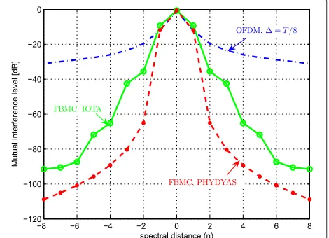
Based on Equation 1, we can construct a table of mutual interference as a function of the spectral distancel. The PSD-based interference tables for CP-OFDM are given in Table 1 for different values of CP duration:=0,T/8 and
T/4. Moreover, we give in Table 2 the PSD-based interfer-ence tables for FBMC considering PHYDYAS and IOTA waveforms [9].
It is worth to point out that these tables are symmetrical as shown in Figure 2.
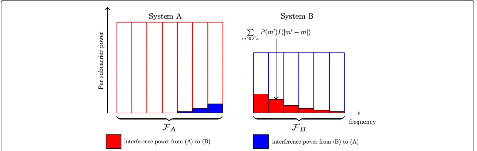
In Figure 3, we illustrate how to compute the interfer-ence caused by the different subcarriers ofFAto a given subcarriermof system (B). The total interference is the sum of the contribution of each interfering subcarrierm, and can thus be written as
Itot=
m∈FA
P(m)I(|m−m|), (7)
whereP(m)is the transmitted power on them-th inter-fering subcarrier andI(m−m)is the PSD-based interfer-ence weight computed in Tables 1 and 2.
Various analysis have been developed based on this interference estimation, e.g., SINR, spectral efficiency analysis in [9,20], and resource allocation algorithms [14,20].
According to (1), one can see that the interference remains the same for any timing misalignment between the transmitted signals of both systems since the sig-nals are considered to be non-orthogonal. However, in CP-OFDM systems, the orthogonality between the differ-ent transmit signals is maintained as long as the timing misalignment does not exceed the cyclic prefix dura-tion. This example highlights the overestimation of the asynchronous interference term. In fact, the real asyn-chronous interference is always a function of the timing offset between the considered asynchronous systems that is not taken into account in the PSD-based interference tables generation.
Table 1 OFDM mutual interference tables based on the PSD for=0,T/8 andT/4, respectively
l =0 =T/8 =T/4
[dB] [dB] [dB]
0 -01.11 -00.87 -00.70
1 -11.04 -12.00 -13.08
2 -18.52 -19.72 -20.72
3 -22.30 -23.55 -23.16
4 -24.88 -25.98 -25.14
5 -26.86 -27.62 -27.97
6 -28.46 -28.83 -30.34
7 -29.82 -29.92 -30.72
Table 2 FBMC mutual interference tables based on the PSD for PHYDYAS and IOTA waveforms, respectively
l PHYDYAS IOTA
[dB] [dB]
0 -00.58 -00.70
1 -11.95 -09.27
2 -65.02 -35.56
3 -80.30 -42.55
4 -89.22 -65.17
5 -95.68 -71.72
6 -100.80 -87.31
7 -105.08 -90.53
8 -108.80 -91.45
In the next section, we propose new interference tables that model the correlation between the interfer-ing subcarrier and the victim one considerinterfer-ing the timinterfer-ing offset between them in addition to the different param-eters already considered by the PSD-based interference tables.
3 Instantaneous OFDM/FBMC interference tables
To take into account the detrimental effects of interfer-ence caused by the imperfect synchronization in multicar-rier techniques, we consider the system model depicted in Figure 4. We refer, here, to a receiver which suffers from the interference coming from an asynchronous transmit-ter. This receiver is assumed to be perfectly synchronized with its corresponding transmitter. Moreover, the timing offsetτand the phase offsetϕare assumed to be uniform random variables that are distributed on τ ∈[0,T] and ϕ ∈[0, 2π], respectively. In the following analysis, we will be interested in the impact of the interfering signals(t−τ ) on the reference receiver.
Figure 2PSD-based interference tables of OFDM and FBMC.
3.1 CP-OFDM case
Consider the following asynchronous signal coming from the interferer on them-th subcarrier
sm(t−τ,ϕ)= n=+∞
n=−∞
xm,nfT(t−n(T+)−τ )
×ej 2Tπm(t−n(T+)−τ )+ϕ
,
(8)
where
• xm,nare the complex data symbols transmitted by the interferer.
• T andare the useful OFDM symbol duration and the CP duration, respectively.
• The timing offset and the phase offset between the reference receiver and the interferer are respectively denoted byτandϕ.
Here,fT(t)andfR(t)are, respectively, the transmit and the receiver pulse shapes,
fT(t)=
1
√
T t∈[0,T+]
0 elsewhere
fR(t)=
1
√
T t∈[,T+]
0 elsewhere
Them0-th output of the receiver filter on then0-th
signal-ing interval comsignal-ing fromsm(t−τ,ϕ), will be
ym0,n0(τ,ϕ)= sm(t−τ,ϕ),fR(t−n0(T+))
×ej2Tπm0(t−n0(T+))
=
+∞
−∞
sm(t−τ,ϕ)fR(t−n0(T+))
×e−j2Tπm0(t−n0(T+))dt
=
+∞
n=−∞
xm,ne−j
2π
Tmτ−ϕ
+∞
−∞
fT(t−n(T+)−τ)
×fR(t−n0(T+))ej
2π
Tm(t−n(T+))
×e−j2Tπm0(t−n0(T+))dt, (9)
Figure 3Illustration of how to compute the interference caused by a set of subcarriers.
In the general case, we see that the productfT(t−n(T+ )−τ )fR(t−n0(T+))and the choice ofτdetermine the
limits of the integral appearing in (9), we have then two cases to analyze
3.1.1 Case 1: (0< τ < )
In this case, the positions of the receiver window and the interferer window are depicted in Figure 5 and the signal
ym0,n0(τ )becomes
ym0,n0(τ,ϕ)=xm,n0e−j 2π
Tmτ−ϕ
(n0+1)(T+)
n0(T+)+
1
Te
j2Tπ(m−m0)(t−n0(T+))dt
= ⎧ ⎨ ⎩
xm0,n0e−
j 2π
Tm0τ−ϕ
m=m0
0 otherwise
(10)
Here, the timing offsetτ is absorbed by the cyclic prefix . The interference will only occur on the same subcarrier
m=m0, the other subcarriers are free of interference due
to the orthogonality between them.
3.1.2 Case 2: ( < τ <T+)
As illustrated in Figure 6, the productfT(t−n(T +)− τ )fR(t−n0(T+))is nonzero whenn=n0−1 andn=n0,
simultaneously. Consequently, the signalym0,n0(τ )can be
written as follows:
ym0,n0(τ,ϕ)=e−
j 2π
Tmτ−ϕ
⎧ ⎪ ⎨ ⎪ ⎩xm,n0−1
n0(T+)+τ
n0(T+)+
1
T
+ej2Tπm(t−(n0−1)(T+))e−j2
π
Tm0(t−n0(T+))dtxm,n
0
×
(n0+1)(T+)
n0(T+)+τ
1
Te
j2Tπ(m−m0)(t−n0(T+))dt
⎫ ⎪ ⎬ ⎪ ⎭
=e−j 2Tπmτ−ϕ
⎧ ⎪ ⎨ ⎪ ⎩
xm,n0−1
T e
−j2Tπm(T+)
n0(T+)+τ
n0(T+)+
×ej2Tπ(m−m0)(t−n0(T+))dtxm,n0
T
+
(n0+1)(T+)
n0(T+)+τ
ej2Tπ(m−m0)(t−n0(T+))dt
⎫ ⎪ ⎬ ⎪ ⎭.
(11)
Figure 5Respective positions of transmit and receiver pulses whenτ∈[0,].
Whenm=m0equation (11) is reduced, upon the change
of variablest=t−n0(T+), to
ym0,n0(τ,ϕ)=e−j 2π
Tmτ−ϕ
⎧⎨ ⎩
xm,n0−1
T e
−j2Tπm(T+)
τ
×ej2Tπ(m−m0)tdt+xm,n0
T
(T+)
τ
ej2Tπ(m−m0)tdt
⎫ ⎬ ⎭
=e−j 2Tπmτ−ϕ
xm,n
0−1
j2π(m−m0)
e−j2Tπm(T+)
×ej2Tπ(m−m0)τ−ej2Tπ(m−m0)+ xm,n0
j2π(m−m0)
× ej2Tπ(m−m0)(T+)−ej2Tπ(m−m0)τ
.
(12)
Using some trigonometric transformations, the signal
ym0,n0(τ )can be written in the following form:
ym0,n0(τ,ϕ)=e−j 2π
Tmτ−ϕ
x m,n0−1
π(m−m0)e
−j2Tπm(T+) ×ejTπ(m−m0)(τ+)sin [π(m−m0)(τ−)/T]
+ xm,n0
π(m−m0)e
jπT(m−m0)(T++τ )
× sin [π(m−m0)(T+−τ )/T]
. (13)
whenm=m0, the signalym0,n0(τ )is given by
ym0,n0(τ,ϕ)=e−j 2π
Tm0τ−ϕ
xm0,n0−1e−j 2π
Tm0(T+)τ −
T
+xm0,n0
T+−τ
T
. (14)
Accordingly, when the timing offsetτ is larger than the cyclic prefix duration, the orthogonality between sub-carriers is damaged. Thus, the interference is caused by all subcarriers.
As the communication symbols xm,n are zero mean uncorrelated variables, the corresponding interference power is the sum of the interference power coming respectively from two successive data symbols (xm,n−1,
xm,n). Without loss of generality, we assume that E[|xm,n|2]= 1, we can define the instantaneous interfer-ence tables by the following expression:
I(τ,l)=Ex
ym0,n0(τ,ϕ)
2
= ⎧ ⎪ ⎪ ⎨ ⎪ ⎪ ⎩
δ(l) τ∈[0,]
(T+−τ )2+(τ−)2/T2 τ∈[,T+] ,l=0
sin(πl(T+−τ )/T) πl
2
+sin(πl(τ−)/T) πl
2
τ∈[,T+] ,l=0 (15)
whereδ(l)is the Kronecker delta andl= |m−m0|is the spectral distance between the interfering subcarrier and the victim one.
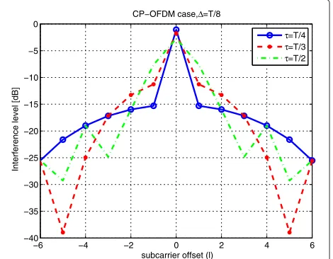
According to (15), the OFDM interference power tables do not depend on the phase offsetϕ. In Table 3, we give some examples of the instantaneous interference tables for τ = T/4,T/3 and T/2. These examples are also depicted in Figure 7 where we see that the interference level vary with respect to the timing offset τ and the spectral distancel.
3.1.3 OFDM mean interference table
In order to calculate the mean interference tableI(l), we assume a timing offsetτ uniformly distributed in [0,T+
],
I(l)=
τ
I(τ,l)p(τ )dτ, (16)
where p(τ ) is the probability density function of the random variableτ,
p(τ )=
1/(T+) τ ∈[0,T+]
0 elsewhere (17)
Substituting (15) and (17) into (16), we obtain
Table 3 OFDM instantaneous interference tables for
τ = {T/4,T/3,T/2}
l τ=T/4 τ=T/3 τ=T/2
[dB] [dB] [dB]
0 -01.06 -01.72 -02.73
1 -15.29 -11.27 -07.63
2 -15.98 -13.28 -15.98
3 -17.18 -17.17 -24.83
4 -19.00 -24.95 -19.00
5 -21.62 -38.96 -29.27
6 -25.52 -25.58 -25.52
−6 −4 −2 0 2 4 6
−40 −35 −30 −25 −20 −15 −10 −5 0
subcarrier offset (l)
Interference level [dB]
CP−OFDM case, Δ=T/8
τ=T/4
τ=T/3
τ=T/2
Figure 7OFDM instantaneous interference tables for τ= {T/4,T/3,T/2}.
case 1(l=0)
I(0)= 1
T+
⎡ ⎣
0 dτ+
T+
(T+−τ )2+(τ−)2
T2 dτ
⎤ ⎦
= 2T+3
3(T+). (18)
case 2(l=0)
I(l)= 1
T+
T+
sin(πl(T+πl−τ )/T)2
+sin(πl(τ−)/T)
πl
2dτ = T
(πl)2(T+).
(19)
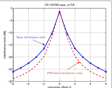
The OFDM mean interference table is compared to the PSD-based OFDM interference table in Figure 8 and Table 4. We can see that the two interference levels com-puted by the PSD and the proposed interference tables are quite different. In fact, the bigger the spectral distance is, the greater the gap in interference level becomes. It must be noted that, except forl=0, the interference lev-els presented by the proposed model is higher than the PSD-based one.
3.2 FBMC case
Figure 8OFDM mean interference table vs. PSD-based OFDM interference table.
of conventional QAM ones, where the in-phase and the quadrature components are time staggered by half a symbol period, T/2 [21]. The second specificity of this scheme is that considering two successive subcarri-ers, the time delayT/2 is introduced into the imaginary part of the QAM symbols on one of the subcarri-ers, whereas it is introduced into the real part of the symbols on the other one [22,23]. It is worth noticing that the spacing between two successive subcarriers is 1/T.
According to [22], the continuous-time baseband FBMC transmit signal can be written
s(t)= N−1
m=0
+∞
n=−∞
am,nγm,n(t), (20)
whereN is the number of subcarriers,am,nare the real-valued transmitted data symbols andγm,nis defined by
Table 4 OFDM mean interference table vs. PSD-based OFDM interference table
l Mean interf. table PSD interf. table
[dB] [dB]
0 -01.51 -00.87
1 -10.48 -12.00
2 -16.50 -19.72
3 -20.02 -23.55
4 -22.52 -25.98
5 -24.45 -27.62
6 -26.04 -28.83
γm,n(t)=g(t−nT/2)ej2Tπmtejϕm,n, (21)
and with
ϕm,n= π
2(n+m)−πnm. (22)
According to (20), we can define the asynchronous sig-nal coming from the interferer on the m-th subcarrier
sm(t−τ,ϕ)as follows:
sm(t−τ,ϕ)=
+∞
n=−∞
am,nγm,n(t−τ )ejϕ. (23)
Them0-th output of the receiver filter on then0-th sig-nalling interval (i.e.,t=n0T/2) coming fromsm(t−τ,ϕ), will be
ym0,n0(τ,ϕ)= sm(t−τ,ϕ),γm0,n0(t)
=
+∞
−∞
sm(t−τ,ϕ)γm∗0,n0(t)dt. (24)
Substituting (23) and (21) in (24), the signal ym0,n0(τ )
becomes
ym0,n0(τ,ϕ)= +∞
n=−∞
am,nej(ϕ+ϕm,n−ϕm0,n0)e−j2 π
Tmτ
+∞
−∞
×g(t−nT/2−τ )g(t−n0T/2)ej
2π
T(m−m0)tdt.
(25)
In order to get simplified, easier-to-manipulate expres-sions, let us define the following integral
(t,τ,l) t2
t=t1
= t2
t1
g(t−τ )g(t)ej2Tπltdt. (26)
(t,τ, 0)
whereAis the normalization factor
A=
Without loss of generality, let us assume that the pro-totype filterg(t) can be non zero only whent ∈[0,KT] where K represents its overlapping factor. Accordingly, the product g(t)g(t−τ )can be nonzero only when the
timing offset τ ∈[−KT,+KT]. Therefore in order to computeym0,n0(τ ), we have to consider two cases:
3.2.1 Case 1 : ((n0−n)T2< τ) In this case, (25) and (26) yield
ym0,n0(τ,ϕ)=
whereαdenotes the floor function (the largest integer less than or equal toα).
3.2.2 Case 2 : (τ < (n0−n)T2)
According also to (25) and (26), we obtain
ym0,n0(τ,ϕ)=
whereαis the ceil function (the smallest integer greater than or equal toα).
After the OQAM decision, we can write the total com-plex symbolytot(τ,ϕ)as follows:
and the corresponding interference power tableI(τ,l)can thus be given by the following expression:
I(τ,l)=Eam,n,ϕ
ytot(τ,ϕ)2
. (33)
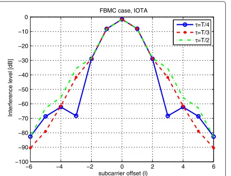
In Figures 9 and 10, PHYDYAS and IOTA interference tablesI(τ,l)are plotted for different values of the timing offset τ = T/4,T/3,T/2. We also see that the inter-ference varies with respect to the timing offset τ and the spectral distancelbetween the interfering subcarrier and the victim one. Furthermore, PHYDYAS and IOTA mean interference tables are compared to the respec-tive PSD-based interference tables in Figures 11 and 12, respectively. Looking at these figures, we find that the two models lead to different results. However, this difference is negligible when the interference level is high.
4 Asynchronous interference in frequency selective channels
−6 −4 −2 0 2 4 6 −120
−100 −80 −60 −40 −20 0
Interference level [dB]
subcarrier offset (l) FBMC case, PHYDYAS K=4
τ=T/4
τ=T/3
τ=T/2
Figure 9FBMC instantaneous interference tables for τ= {T/4,T/3,T/2}: PHYDYAS case.
multipath channel, where its equivalent sample-spaced impulse response [24] is given by
h(t)= L−1
i=0 hiδ(t−
ni
NT), (34)
where n0 < n1 < ... < nL−1 < C and C is the
maximum delay spread of the channel normalized by the sampling period (T/N), and hi are the complex chan-nel path gains, which are assumed mutually independent, where E[hih∗i]= γi, andE[hih∗j]= 0 when i = j. We further assume that the power is normalized such that L$−1
i=0
γi=1.
−6 −4 −2 0 2 4 6
−100 −90 −80 −70 −60 −50 −40 −30 −20 −10 0
Interference level [dB]
subcarrier offset (l) FBMC case, IOTA
τ=T/4
τ=T/3
τ=T/2
Figure 10FBMC instantaneous interference tables for τ= {T/4,T/3,T/2}: IOTA case.
Figure 11FBMC mean interference table vs. PSD-based FBMC interference table : PHYDYAS case.
In this case, the interference signal received at the input of the multicarrier demodulatorr(t−τ,ϕ)is given by
r(t−τ,ϕ)=h(t) s(t−τ,ϕ), (35)
wherestands for the convolution product.
In the following analysis, we investigate the effects of the propagation channel on the asynchronous interfer-ence signal coming from them-th subcarriersm(t−τ,ϕ). In the following analysis, two cases will be investigated : CP-OFDM case and FBMC one.
Figure 13Asynchronous interference in the presence of multi-path effects.
4.1 CP-OFDM case
According to (8) and (35), the interference signal at the input of the OFDM receiver can be written as follows:
r(t−τ,ϕ)=h(t) sm(t−τ,ϕ)=
In weakly and mildly frequency selective channels,ni
NT is
N m representing the complex
channel gain at them-th subcarrier.
Based on (37), (10) and (14), the m0-th output of the receiver filter on then0-th signalling interval result-ing from the received interference signal r(t − τ,ϕ) is
Consequently, the resulting interference powerPinterfwill
be the product of the channel power gain of the interfer-ing subchannel and the correspondinterfer-ing interference weight given in (3). Then, we write the interference power in
m0-th subchannel as
Pinterf(m0,τ )=Ptrans(m)I(τ,|m−m0|)|H(m)|2, (41)
where,
• Ptrans(m)is the transmitted power on the subchannel
m.
4.2 FBMC case
Similarly, we express the interference signal received at the input of the FBMC receiverr(t−τ,ϕ). According to (23) and (35), we write
r(t−τ,ϕ)=h(t) sm(t−τ,ϕ)=
Substituting (21) in (42), we obtain
r(t−τ,ϕ)= relatively slow variations when ni
NT ∈[0,τds] (τds is the
maximum delay spread of the channel) [25,26]. Indeed, compared to the coherence bandwidthBc, the filter band-width is very small, which also means that the time varia-tions of the prototype filterg(t)are necessarily limited.
Consequently, the signalr(t−τ,ϕ)becomes
According (32) and (45), the output signal after the OQAM decision is given by
ytot(τ,ϕ)= |H(m)|ytot(τ,ϕ+ϕH(m)), (46)
where,ytot(τ,ϕ)is given in (32).
Now, let ϕ and ϕ be two uniform random variables defined in the following intervals ϕ ∈[0, 2π] and ϕ ∈
Therefore, the corresponding interference powerPinterfis also the product of the channel power gain of the inter-fering subcarrier|H(m)|2and the corresponding interfer-ence weight given in (33). Thus, the interferinterfer-ence power at them0-th subchannel is given by
Pinterf(m0,τ )=Ptrans(m)I(τ,|m−m0|)|H(m)|2. (47)
In general, the asynchronous interference power arriv-ing through a frequency selective channel can be calcu-lated using the following expression:
Pinterf(m0,τ )=d−βPtrans(m)I(τ,|m−m0|)|H(m)|2,
(48)
where,
• d is the distance between the interferer and the victim user.
• βis the path loss exponent.
• Ptrans(m)is the transmitted power on the interfering
subchannelm.
• I(τ,|m−m0|)is the interference weight for the timing offsetτ and the spectral distance|m−m0|. • |H(m)|2is the channel power gain between the
interfering transmitter and the victim receiver on subchannelm.
In the next section, we investigate the accuracy of the pro-posed interference modeling expressed by Equation 48. Various applications and scenarios can be studied using this interference model.
5 Simulation results
In this section, we consider the uplink transmission in OFDM/FBMC-based network depicted in Figure 14a. The reference mobile user MU0and the interfering one MU1
communicating respectively with BS0and BS1. Moreover,
MU0and MU1are respectively located at distancesd0and dfrom the reference base station BS0. It is assumed that,
the transmitted power of each user must guarantee a tar-get signal to noise ration SNRt=20 dB at its base station
(BS0for MU0and BS1for MU1).
Concerning the frequency scheme, the subcarriers are allocated according to the scheme described in Figure 14b where, the size of each subcarrier block is set at 18 subcar-riers. Here, we have chosen the practical size of subcarrier block in WiMax 802.16 [27].
(a)
(b)
Figure 14Interference model.(a)The reference user coexists with an asynchronous interferer.(b)Subcarrier assignment for both coexisting systems.
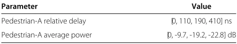
and the reference base station BS0are denoted byh0and h1, respectively. The considered model is the Pedestrian-A model whose parameters are given in Table 5. The choice of this model is based on the assumption that the sub-carriers of interest experience flat fading. Therefore, the interference caused by the multipath effects are negligible compared to the one caused by time asynchronism, in the FBMC case.
Furthermore, the underlying channel model includes path loss effects which takes into account the position of the mobile user with respect to the reference base station BS0. The path loss of a received signal at distancedis
gov-erned by the following expression [28] corresponding to a
Table 5 Channel parameters used in simulations
Parameter Value
Pedestrian-A relative delay [0, 110, 190, 410] ns Pedestrian-A average power [0, -9.7, -19.2, -22.8] dB
path loss exponentβ =3.76 and a carrier frequency of 2 GHZ
loss(d)=128.1+37.6 log10(d[km])[dB] .
On the other hand, we consider a system withN =1, 024 subcarriers and a sampling frequency of 10 MHz. The noise term is considered as a thermal noise with spectral densityN0= −174 dBm/Hz.
Each mobile user is assumed to be perfectly synchro-nized with its corresponding base station but it is not synchronized with the other base station. Because of the timing misalignment between MU1 and BS0, the
sig-nal arriving from MU1 at BS0 appears non-orthogonal
to the desired signal arriving from MU0. This
instanta-neous SINR on a given subcarrier m ∈ F0 can be
expressed as
SINR(m)
= d
−β
0 Ptrans(m)|H0(m)|2 $
m∈F1
d−βP
trans(m)I(τ,|m−m|)|H1(m)|2+N0f
,
(49)
where f is the subcarrier spacing. Actually, the SINR expression given in (49) is established assuming the absence of ISI and ICI terms. Such an assumption is valid in the Pedestrian-A channel model.
Here, it is worth mentioning that the interference weight
I is computed by two methods : PSD-based interference tables and our proposed interference tables.
The objective of this section is to evaluate the average SINR and the spectral efficiency expressed, respectively by
SINRaverage(m)=E[SINR(m)] , (50)
Caverage(m)=E log2(1+SINR(m))
, (51)
where E[ .] stands for the statistical expectation which is computed over all channel realizations (H0(m), "
H1(m),m∈F1 #
) and all values of the timing offset τ which is uniformly distributed over [0,T].
Two different contexts will be analyzed as depicted in Figure 14:
• The classical multi-cellular context: whend varies fromR to2R, i.e., MU1can move from the edge to
the center of cell1
• The cognitive radio context: whend varies from 0 to 2R, i.e., MU1can be very close to BS0while
transmitting to BS1.
It is worth mentioning that, in cognitive radio scenarios, we cannot always assume that both primary and sec-ondary users are using OFDM or FBMC. However, the objective here is to highlight the potential gain that can be achieved when both primary and cognitive systems are using either OFDM or FBMC waveform.
In Figures 15, 16, and 17, we investigate, respectively, the accuracy of the SINR expression in the CP-OFDM, FBMC-PHYDYAS, and FBMC-IOTA cases. The averaged SINRs over all subcarriersm∈F0are plotted against the
distanced, using the instantaneous tables (line), the PSD-based table (point markers), and numerical simulation (cross markers). The instantaneous table results depicted in these figures show a perfect match to the correspond-ing simulation results. However, the PSD-based method
0.2 0.4 0.6 0.8 1 1.2 1.4 1.6 1.8
−20 −15 −10 −5 0 5 10 15 20
d / R
SINR [dB]
CP−OFDM case, Δ=T/8
inst. Tables simulation PSD−Table
CR context Cellular context
Figure 15CP-OFDM average SINR vs. distance between MU1and BS0,τ∈[0,T].
exhibits a strong inaccuracy especially in the cognitive radio context.
In the cognitive radio context, we observe a signifi-cant degradation of the OFDM SINR with respect to the target SNR (20 dB). Such a result can be explained by the high level of OFDM asynchronous interference caused by the timing misalignment which damages the orthogonality between the subcarriers. On the other hand, we notice a slight loss of the FBMC SINR with respect also to the target SNR of 20 dB. The better perfor-mance of PHYDYAS-FBMC compared to IOTA-FBMC and CP-OFDM can be justified by the fact that only the two subcarriers on the edge of the cluster (subcar-rier block) F0 suffers from the interference caused by
their immediate adjacent subcarriers in F1 as depicted
0.2 0.4 0.6 0.8 1 1.2 1.4 1.6 1.8
17.5 18 18.5 19 19.5 20
d / R
SINR [dB]
FBMC case, PHYDYAS
inst. Tables simulation PSD−Table
CR context Cellular context
Figure 17IOTA-FBMC average SINR vs. distance between MU1 and BS0,τ∈[0,T].
in Figure 11; whereas in IOTA-FBMC, two subcarriers at each edge are affected by the asynchronous interfer-ence coming from the two neighboring subcarriers at each edge as shown in Figure 12. Furthermore, the entire clusterF0suffers, in the CP-OFDM case, from the
asyn-chronous interference caused by all subcarriers of F1
(see Figure 8).
In the cellular context, the asynchronous interferer MU1
is quite far from the reference base station BS0and, at the
same time, it is close to its base station BS1. This means
that its transmitted power is reduced and consequently the interference power received by BS0will be much lower
due to the path loss effect (dis quite large). Therefore, the impact of the asynchronous interference is less significant in the cellular context for all waveforms. Also, it is worth mentioning that SINRs of OFDM and FBMC converge to the target SNR (20 dB) when MU1is very far from BS0as
the interference becomes negligible compared to the noise level.
The impact of the asynchronous interference on the average spectral efficiency has also been investigated. Figure 18 shows the average spectral efficiency over all subcarriers m ∈ F0 against the distance d, for
CP-OFDM (solid line−), FBMC-PHYDYAS (dashed-dotted line −.), and FBMC-IOTA (dashed line −−). Also, the accuracy of instantaneous and PSD-based tables is exam-ined. Figure 18 shows that timing synchronization errors cause a degradation of the spectral efficiency. The same remarks can be formulated, here, where the FBMC system still outperforms the OFDM system. Furthermore, simu-lation and instantaneous tables results shown in Figure 18 validate the accuracy of the proposed interference model while the PSD-based tables still present a strong inaccu-racy with respect to simulation results especially in the
Figure 18Spectral efficiency vs. distance between MU1and BS0,
τ∈[0,T].
cognitive radio context where the noise level becomes negligible compared to the asynchronous interference caused by MU1. We see that both modulation schemes
(OFDM and FBMC) lead to identical spectral efficiency floor when MU1is close to its base station because of the
predominance of the noise term. We have to remind that the actual bit rate is lower for CP-OFDM because of the redundancy introduced by the cyclic prefix in each OFDM block.
6 Conclusion
In this paper, we have investigated the asynchronous interference modeling in OFDM and FBMC systems. First, the general concept of interference tables has been introduced where we have derived the PSD-based inter-ference tables of CP-OFDM and FBMC for two con-sidered waveforms: PHYDYAS and IOTA. It has been noticed that the PSD-based tables do not consider the timing offset between the interferer and the victim user.
Next, we have proposed new interference tables that model the correlation between a given interfering sub-carrier and the victim one, not only as a function of the spectral distance separating both subcarriers but also with respect to the timing misalignment between the subcar-rier holders. Theoretical expressions of these tables have been derived for both OFDM and FBMC systems.
The interference analysis has been extended to the case of frequency selective environments where we have pro-posed a table-based estimation method as a computation-ally simpler alternative to the numerical evaluation; as the latter requires huge computational efforts.
the results based on the instantaneous tables method shows an excellent match with the corresponding simu-lation ones. In contrast to the instantaneous interference tables, we have shown through this evaluation that the PSD modeling exhibits a strong inaccuracy with respect to the numerical results.
Finally, through this evaluation, we have shown that in OFDM case, timing asynchronism between coexist-ing systems cause a severe degradation in the perfor-mance. This result is explained by the loss of orthogonality between all system subcarriers. In contrast to the OFDM system, the FBMC waveforms are demonstrated to be less sensitive to the timing misalignment between the cohab-iting systems due to the better frequency localization of the prototype filter. The obtained results make FBMC a promising candidate for the physical layer of future cognitive radio systems.
Appendix
Proof of the expressions (27) and (28)
Let us first recall the impulse response of the PHYDYAS prototype filter which is given in [29],
g(t)=
whereAis the normalization factor
A=
Substituting the expression (52) in (26), we obtain whenl=0
Using some trigonometric transformations, the integral
(t,τ, 0) t2
t=t1
can be written in the following form:
(t,τ,0)
After integration, we get
After integration, we obtain
The authors declare that they have no competing interests.
Author details
1ICTEAM, Université catholique de Louvain, Place du Levant, 2,
Louvain-la-Neuve 1348, Belgium.2CNAM - CEDRIC/LAETITIA, 292 rue Saint-Martin, Paris 75003, France.
Acknowledgments
This work has been partially supported by European Commission through the Emphatic project (ICT-318362).
Received: 1 December 2013 Accepted: 7 April 2014 Published: 23 April 2014
References
1. J Mitola J, Cognitive radio: an integrated agent architecture for software defined radio. PhD thesis, Royal Institute of Technology, Stockholm, Sweden, 2000
2. M Bellanger, Physical layer for future broadband radio systems, inIEEE Radio and Wireless Symposium (RWS), 2010(IEEE Piscataway, 2010), pp. 436–439
3. C Stevenson, G Chouinard, Z Lei, W Hu, SJ Shellhammer, WM Caldwell, IEEE 802.22: the first cognitive radio wireless regional area network standard. IEEE Comm. Mag.47(1), 130–138 (2009)
4. B Le Floch, M Alard, C Berrou, Coded orthogonal frequency division multiplex [TV broadcasting]. Proc. IEEE.83(6), 982–996 (1995) 5. B Farhang-Boroujeny, OFDM versus filter bank multicarrier. IEEE Signal
Process. Mag.28(3), 92–112 (2011)
6. M Alard, Construction of a multicarrier signal (Patent WO/1996/035278) (1996). Available in WIPO: http://patentscope.wipo.int/search/en/ WO1996035278. Accessed Nov 2013
7. R Zakaria, D Le Ruyet, A novel filter-bank multicarrier scheme to mitigate the intrinsic interference: application to MIMO systems. IEEE Trans. Wireless Commun.11(3), 1112–1123 (2012)
8. LG Baltar, DS Waldhauser, JA Nossek, Out-of-band radiation in multicarrier systems: a comparison, inMultiCarrier Spread Spectrum, vol. 1 (Springer Netherlands, 2007), pp. 107–116
9. H Zhang, DL Ruyet, M Terré, Spectral efficiency comparison between OFDM/OQAM and OFDM based CR networks. Wireless Commun. Mobile Comput. Wiley.9, 1487–1501 (2009)
10. P Siohan, C Roche, Cosine-modulated filterbanks based on extended Gaussian functions. IEEE Trans. Signal Process.48(11), 3052–3061 11. M Bellanger, D Le Ruyet, D Roviras, M Terré, J Nossek, L Baltar, Q Bai, D
Waldhauser, M Renfors, T Ihalainen, A Viholainen, TH Stitz, J Louveaux, A
Ikhlef, V Ringset, H Rustad, M Najar, C Bader, M Payaro, D Katselis, E Kofidis, L Merakos, A Merentitis, N Passas, A Rontogiannis, S Theodoridis, D Triantafyllopoulou, D Tsolkas, D Xenakis, M Tanda, et al., FP7-ICT PHYDYAS - Physical layer for dynamic spectrum access and cognitive radio. http:// www.ict-phydyas.org. Accessed Nov 2013
12. M Bellanger, Specification and design of a prototype filter for filter bank based multicarrier transmission, inProceedings of IEEE Int. Conf. on Acoustics, Speech, and Signal Processing, 2001. (ICASSP ‘01), vol. 4 (2001) (IEEE Piscataway, NJ, 2001), pp. 2417–2420
13. T Weiss, J Hillenbrand, A Krohn, FK Jondral, Mutual interference in OFDM-based spectrum pooling systems, inIEEE 59th Vehicular Technology Conference, vol. 4 (IEEE Piscataway, 2004), pp. 1873–1877
14. M Shaat, F Bader, An uplink resource allocation algorithm for OFDM and FBMC based cognitive radio systems, inProceedings of the Fifth International Conference On Cognitive Radio Oriented Wireless Networks Communications (CROWNCOM), 2010(IEEE Piscataway, 2010), pp. 1–6 15. T Fusco, A Petrella, M Tanda, Sensitivity of multi-user filter-bank
multicarrier systems to synchronization errors, inCommunications, Control and Signal Processing, 2008. ISCCSP 2008. 3rd International Symposium On
(IEEE Piscataway, 2008), pp. 393–398
16. H Saeedi-Sourck, Y Wu, JWM Bergmans, S Sadri, B Farhang-Boroujeny, Complexity and performance comparison of filter bank multicarrier and ofdm in uplink of multicarrier multiple access networks. IEEE Trans. Signal Process.59(4), 1907–1912 (2011)
17. M Khodjet-Kesba, C Saber, D Roviras, Y Medjahdi, Multicarrier interference evaluation with jointly non-linear amplification and timing errors, in
Vehicular Technology Conference (VTC Spring), 2011 IEEE 73rd(IEEE Piscataway, NJ, 2011), pp. 1–5
18. Y Medjahdi, D Le Ruyet, D Roviras, H Shaiek, R Zakaria, On the impact of the prototype filter on fbmc sensitivity to time asynchronism, inWireless Communication Systems (ISWCS), 2012 International Symposium On(IEEE Piscataway, 2012), pp. 939–943
19. D5.1 D, Prototype Filter and Structure Optimization. Technical report, European project ICT-211887 PHYDYAS (2009)
20. H Zhang, DL Ruyet, D Roviras, Y Medjahdi, H Sun, Spectral efficiency comparison of OFDM/FBMC for uplink cognitive radio networks. EURASIP J. Adv. Signal Process (2010)
21. B Saltzberg, Performance of an efficient parallel data transmission system. IEEE Trans. Commun. Tech.15(6), 805–811 (1967)
22. P Siohan, C Siclet, N Lacaille, Analysis and design of OFDM/OQAM systems based on filter bank theory. IEEE Trans. Signal Process.50(5), 1170–1183 (2002)
23. H Bölcskei, Orthogonal frequency division multiplexing based on offset QAM. Adv. Gabor Anal., 321–352 (2003)
24. L Deneire, ed. by M Engels, Beating the wireless channel, inWireless OFDM Systems, vol. 692 (Springer USA, 2002), pp. 75–93
25. C Lélé, OFDM/OQAM: méthodes d’estimation de canal, et combinaison avec l’accés multiple CDMA ou les systémes multi-antennes. PhD thesis, Conservatoire National des Arts et Métiers, Paris, France, 2008
26. H Lin, P Siohan, P Tanguy, J-P Javaudin, An analysis of the EIC method for OFDM/OQAM systems. J. Commun.4(1), 52–60 (2009)
27. K Etemad, M-Y Lai,WiMAX Technology and Network Evolution. (Wiley, IEEE Press, Piscataway, 2011)
28. ETSI, Universal Mobile Telecommunications System (UMTS); Radio Frequency (RF) System Scenarios. ETS TR 125 942, Eur. Telecommun. Standard Institute (2010)
29. M Bellanger, D Le Ruyet, D Roviras, M Terré, J Nossek, L Baltar, Q Bai, D Waldhauser, M Renfors, T Ihalainen, A Viholainen, TH Stitz, J Louveaux, A Ikhlef, V Ringset, H Rustad, M Najar, C Bader, M Payaro, D Katselis, E Kofidis, L Merakos, A Merentitis, N Passas, A Rontogiannis, S Theodoridis, D Triantafyllopoulou, D Tsolkas, D Xenakis, M Tanda, et al., FBMC physical layer: a primer. Technical report, PHYDYAS (Physical layer for dynamic access and cognitive radio)[Online]. Available: http://www.ict-phydyas. org. Accessed Nov 2013
doi:10.1186/1687-6180-2014-54

![Figure 6 Respective positions of transmit and receiver pulses when τ ∈ [ �, T + �].](https://thumb-us.123doks.com/thumbv2/123dok_us/898687.1108313/6.595.58.544.576.721/figure-respective-positions-transmit-receiver-pulses-t-t.webp)

![Figure 15 CP-OFDM average SINR vs. distance between MU1 andBS0, τ ∈ [0, T].](https://thumb-us.123doks.com/thumbv2/123dok_us/898687.1108313/14.595.305.539.86.268/figure-cp-ofdm-average-sinr-distance-mu-andbs.webp)