A TESTING SETUP FOR ANCHOR BOLT CONNECTIONS FOR
REALTIME DYNAMIC LOADING
Andreas Fäcke1, Franz-Herrmann Schlüter2, Ferdinand Borschnek3,Nico Herrmann4 and Harald S. Müller5
1
Project Engineer, SMP Ingenieure im Bauwesen GmbH, Germany 2
Head of SMP Ingenieure im Bauwesen GmbH, Germany 3
Research Engineer, Materials Testing and Research Institute (MPA Karlsruhe), Karlsruhe Institute of Technology (KIT), Karlsruhe, Germany
4
Vice-President, Materials Testing and Research Institute (MPA Karlsruhe), Karlsruhe Institute of Technology (KIT), Karlsruhe, Germany
5
President, Materials Testing and Research Institute (MPA Karlsruhe), Karlsruhe Institute of Technology (KIT), Karlsruhe, Germany
ABSTRACT
The subsequent attachment of safety related pipes and components with metal anchors to RC members are a common practice in nuclear power plants. High safety demands have to be imposed on these connections for regular operation as well as for accidental situations where large dynamic forces may be accompanied by cracks in concrete. While the static load bearing capacity of metal anchors is part of approval tests, the behaviour under dynamic loading is not well understood. There is a need for systematic investigations under realistic conditions with realtime dynamic loading. In this context it is necessary to consider the complete system consisting of anchors, anchor plate and the attached component because effects like shifting of the anchor plate due to regular tolerances and regular limited pull out of anchors in cracked concrete may influence the dynamic response of the system. In the framework of a Federal Ministry of Economics and Technology (BMWi) funded project managed by the project executing part of GRS (Gesellschaft für Anlagen- und Reaktorsicherheit mbH) a new experimental setup for realtime dynamic testing of anchors was developed. Numerical simulations that consider all controlling nonlinear effects at the complete system have been performed in advance in order to support the development of the setup and to reveal possible difficulties. One of the most critical aspects revealed by the analysis is that the dynamic behaviour may considerably change during a test run due to effects like a normal limited pull out of anchors in cracked concrete. The findings from the analysis, the developed mock-up and evaluations of the performed test runs will be presented.
INTRODUCTION
The partial failure of undercut metal anchors at a few post installed components after a regular shutdown of a nuclear power plant in Germany in 2006 and the detection of deficiencies at further anchors during a subsequent check-up has raised attention and revealed safety related questions on this type of fastenings. Because it is common practice to install safety related components with these anchors to the structure high demands have to be imposed on their reliability. The proper load bearing capacity and serviceability has to be provided for normal operating as well as for accidental design situations including earthquake excitation where large dynamic forces may be accompanied by developing and opening of cracks in the concrete fixing ground.
has not yet been investigated under dynamic loading. The common design procedure of components and their fastening is based on linear elastic behaviour of the component and a rigid fixture [ETAG 001]. However nonlinear effects like longitudinal and transversal relative movements between anchor and ground as well as between anchor and plate may influence the dynamic behaviour of the system and in turn the forces acting at the anchors. Longitudinal movements are possible when the anchor is slightly pulled out of the ground. A pull out of a few millimetres is allowed according to design guidelines and can be observed when an anchor under tension is located in a concrete crack. Although it is not allowed to place anchors in dissipative zones like plastic hinges even apart of these zones the occurrence of cracks cannot be ruled out during a seismic event. Transversal movements mainly occur due to unavoidable tolerances at the anchor plate holes and due to shifting of anchors at shear loading. These relative movements at the anchors lead to anchor plate sliding, pounding, limited free tilting of the component and dynamic impact loading on the anchor bolt heads.
In the framework of a Federal Ministry of Economics and Technology (BMWi) funded project managed by the project executing part of GRS (Gesellschaft für Anlagen- und Reaktorsicherheit mbH) it is investigated if nonlinear effects have a significant influence on the forces of fixtures and the dynamic behaviour of the component and in turn on the reliability of common design procedures of fastenings. The investigations will be based on the undercut anchors by Hilti and Fischer that have been used for the majority of post installed components in german nuclear power plants (according to technical approval Z-21.1-1987 respectively Z-21.1-1646). The tests will be performed in uncracked and cracked concrete with crack widths ranging from 0.4 to 1.5 mm. The project started in the year 2012 and will be finished in 2015. Nonlinear dynamic simulations have been performed, a new experimental test setup has been developed and the experimental tests are in progress. This paper shortly describes the numerical model, summarizes the main findings of the numerical simulations, describes the experimental test setup in detail and presents first results of the tests.
TEST LOADS – INVESTIGATED LOAD LEVELS
The numerical and experimental tests are conducted under dynamic loading – a single frequency harmonic excitation at the anchor ground – the concrete block. The dynamic response of the component mass is dependent on the relation between free vibration frequency of the component to the frequency of excitation, the amplitude of excitation and the system damping. Hence the excitation has to be tuned in terms of amplitude and frequency. Three different levels of forces in the anchors are investigated:
1. Serviceability limit state (SLS) 2. Ultimate limit state (ULS) 3. Maximum limit state (MLS)
The SLS and ULS are based on the general expression for the verification of static equilibrium:
Rk
E Ek
M
N N
! " #
! (1)
with the characteristic normal force resistance of the anchor NRk, the characteristic normal force effect of action NEk and the partial safety factors to account for uncertainties of actions !E and resistance !R. The leading failure mechanism of the anchors in this test is actually anchor pull-out named NRk,p. The corresponding characteristic normal force resistance of the Hilti anchor is
Rk ,p c Rk ,p,C20/ 25
For the Fischer anchor it is:
Rk ,p c Rk ,p,C20/ 25
N $ % "N $1.22 17.0" $20.7 kN (1)
Both values are based on the respective technical approvals and a concrete C30/37 (!%c = 1.22).
The factor !R is 1.5 for the Hilti anchor and 1.9 for the Fischer anchor and applies to SLS and ULS. The factor !E equals to 1.0 at SLS and is approximated with 1.4 at ULS. Here, MLS is defined as the state where the anchors reach their mean resistance. The distance between characteristic and mean resistance of the anchors was estimated with a factor of 1.3. The load levels and the corresponding test loads for the Hilti and Fischer anchors are summarized in Table 1.
Table 1: Test load at different load levels (design situations).
Load level Definition Hilti [kN] Fischer [kN]
SLS NRk !M 42.7 1.5$28.5 20.7 1.9 10.9$
ULS ! "E NRk !M &NRk 1.4 42.7 1.5" $39.9 1.4 20.7 1.9 15.3" $
MLS Nm &1.3 N" Rk 1.3 42.7" $55.5 1.3 20.7" $26.9
NUMERICAL SIMULATIONS AND MAIN RESULTS
The experimental test setup is a new development. Hence it was not possible to rely on any experience from former tests for the design of the mock-up. In order to better understand the probable behaviour in advance and to predict potential problems numerical simulations have been performed with a model that represents the main features of the mock-up. It considers nonlinear effects of the anchors like pull-out and horizontal tolerances as well as contact effects between anchor plate and concrete. It is explained in detail in Fäcke et al. 2013.
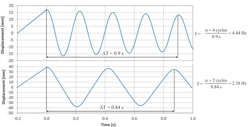
The knowledge of the fundamental eigenfrequency of the system respectively the frequency of free vibration at the nonlinear system with tolerances is essential for tuning the dynamic excitation. The theoretical eigenfrequency of the system without tolerances at the anchors and rigid anchor plate is 5.0 Hz. Considering flexibility of the anchor plate, anchors and concrete results in an eigenfrequency of 4.4 Hz. However due to tolerances and limited pull-out of anchors (here called horizontal and vertical gaps) the frequency of free vibration (here called f) decreases further.
!50 !40 !30 !20 !10 0 10 20 30 40 50
!0.2 0.0 0.2 0.4 0.6 0.8 1.0
D is p la ce m e n t ! [m m ]
Time![s]
!20 !15 !10 !5 0 5 10 15 20 D is p la ce m e n t ! [m m ]
'T = 0.9 s
n 4 cycles 4.44 Hz 0.9 s
$ $
n 2 cycles 2.38 Hz 0.84 s $ $ f = f =
'T = 0.84 s
Figure 1. Free decay after displacement of mass without (top) and with 3 mm vertical gap (bottom).
Table 2 summarizes the results in terms of f of a parametric study of free decay oscillation simulations. No friction between anchor plate and concrete was assumed at these simulations. First, the study was performed at SLS with a variation of the horizontal gap between 0 and 3.0 mm and the vertical gap between 0 and 5.0 mm. The influence of the vertical gap on f is considerably higher than that of the horizontal gap. While the frequency drops off by a factor of 1.86 due to the 3.0 mm vertical gap, it drops off only by a factor of 4.43/3.92 = 1.13 due to the 3.0 mm horizontal gap. Because it is a nonlinear system the frequency of free vibration depends on the response amplitude, too. At a load level of ½ SLS the frequency of free vibration is consistently smaller than at SLS for corresponding gaps. It is vice versa for ULS and even more pronounced at MLS. In further simulations that are not shown here the effect of friction between anchor plate and concrete was investigated. While the influence of the horizontal gap on the free vibration frequency almost vanishes at a small friction assumption of ( = 0.2, the influence of the vertical gap keeps almost the same.
Table 2: Frequency of free vibration as a function of tolerances and load level (hor. and vert. gaps)
Vertical gap uv [mm]
0.0 0.5 1.0 1.5 2.0 3.0 5.0
H o ri zo n ta l g ap uh [ m m ] at S L S
0.0 4.43 3.80 3.35 3.03 2.74 2.38 1.81
1.0 4.21 3.70 3.28 2.99 2.74 2.33 1.77
2.0 3.97 3.39 3.20 2.86 2.65 2.25 1.72
3.0 3.92 3.42 3.07 2.80 2.56 2.20 1.67
uh = 0 a t d if f. l o ad le v el
s ½ SLS 4.43 2.82 2.11 1.68 1.41 1.06 0.78
ULS 4.43 4.00 3.67 3.42 3.17 2.80 2.25
The findings of the influence of tolerances on the frequency of free vibration f (or angular frequency )) as well as the influence of response amplitudes on f are an important aspect that has to be considered at the experimental tests because the response is highly dependent on the relation between frequency of the sinusoidal excitation F (or angular frequency *) and f. The excitation has to be tuned so that *+) is near to 1.0 in order to be able to reach MLS. However due to a low damping in the system *+) =1.0 has to be avoided in order to prevent extreme amplifications.
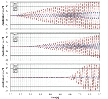
Figure 2 shows three typical cases that may occur during excitation of the system. The system is initially characterized by f = 4.4 Hz. Figure 2 (top) shows the optimum case were F was selected 10% higher than f (F = 4.9 Hz). In this case F was close enough to f to reach MLS and far enough to avoid resonance.
!60 !40 !20 0 20 40 60 A cc e le ra ti o n ! [m /s ²] MLS ULS SLS !60 !40 !20 0 20 40 60 A cc e le ra ti o n ! [m /s ²] MLS ULS SLS MLS ULS SLS !60 !40 !20 0 20 40 60
0.0 1.0 2.0 3.0 4.0 5.0 6.0 7.0 8.0 9.0
A cc e le ra ti o n ! [m /s ²]
Time![s]
MLS ULS SLS MLS ULS SLS MLS ULS SLS MLS ULS SLS
Figure 2. Time histories of excitation (blue) and response (red dashed) for 4.9 Hz-excitation + no gap (top), 4.9 Hz-excitation + 0.5 mm vert. gap (middle) and 4.0 Hz-excitation + 0.5 mm vert. gap (bottom).
increase of amplitudes. The numerical simulations and experiments have indicated that a frequency of F ~ 1.15 · f (f of system before test) leads to a satisfying performance in most cases. If MLS is not reached in a first run a second run with a smaller excitation frequency has to be performed.
EXPERIMENTAL SETUP FOR THE DYNAMIC TESTING OF ANCHOR BOLTS
Figure 3 depicts a drawing of the test setup. It mainly consists of a concrete block, on which an anchor plate is fixed by four anchors, a cantilever with the mass representing the component and a hydraulic jack for the dynamic excitation.
hydraulic jack for excitation of concrete block
horizontal pendulum support (horizontal guidance)
counter bearing
View Top view
hydraulic jack with locking ring for crack width adjustment
cantilever steel hollow profile
anchors mass (component)
crack frame
~
5
0
0
0
~ 4190 dimension in [mm]
1800
1
2
0
0
vertical
pendulum support (horizontal guidance) location of potential crack concrete block
Figure 3. Experimental setup with component, concrete block, supports and actuators.
The concrete block is placed on a “steel table” (dimension 1800 x 1200 mm) which is supported horizontally displaceable, so that the test rig composed of concrete slab and component part with mass can be excited by a hydraulic jack in horizontal direction. The horizontally displace ability is realized by four pendulum supports linked to the “steel table”. To control and adjust the crack in the concrete block there is a crack width adjustment by two hydraulic jacks with locking rings. Additionally, the mass is placed beside the component part (cantilever, steel hollow profile) near the counter bearing and is connected through a horizontal pendulum to the cantilever.
profiles of the “crack frame”, the force of the hydraulic jacks is induced in the concrete block and leads as a consequence to the elongation of the reinforcement to the cracking. After this first cracking, the pressure in the hydraulic system is raised until the target values of the crack widths are reached which are measured by inductive displacement transducer. After the target value is reached the locking rings of the two hydraulic jacks are applied and so the hydraulic jacks are settled. The pressure of the hydraulic system can now be reduced to zero. After this step the aforementioned fixations (clamps) on the profiles of the “crack frame” are used to hold the concrete slab in position. Now the concrete slab is ready for the dynamic excitation.
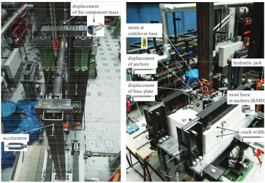
Monitoring – Measuring Units
In Figure 4 a summary of the measuring sensors is shown. At the top of the experimental setup the displacement, of the mass and the connected attachment part, is measured. Also the acceleration of the steel hollow profile is measured. The next area of measuring interest is near the fixation of the cantilever (mounting of the component part). Here the strain at the steel profile (component part) in moving direction is measured by strain gauges. In the area of the anchor plate many points of measurement are placed. So the displacement of the anchor plate relative to the concrete slab is measured in horizontal and vertical direction. The vertical displacement of the four anchors is recorded by inductive displacement transducers. Finally the axial force in the four anchors is measured by load cells (KMD).
acceleration
displacement of base plate displacement of anchors
axial force at anchors (KMD)
crack width hydraulic jack strain at
cantilever base displacement
of the component mass
Figure 4. Measuring units at the top of the mock-up (left) and at the concrete block (right)
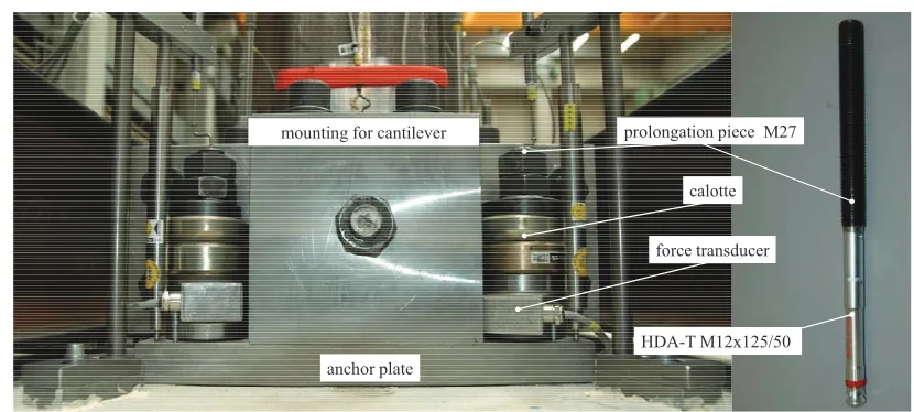
prolongation piece M27
calotte
HDA-T M12x125/50 force transducer
anchor plate mounting for cantilever
Figure 5. Detail of mounting block for component cantilever and force measuring units at anchors.
Experimental Procedure
Due to the complexity of the investigated problem a sequence of preliminary tests has been necessary. Each sequence starts after the inducing and adjusting of the projected crack width. The next step is to measure the natural frequency of the cantilever beam with connected mass. For this reason the test setup was excited by a defined displacement-time curve so that the component part with connected mass deflects dynamically. Now, by stopping the excitation a free vibration of the cantilever with mass is observed. Hence, the natural frequency can be determined through analysing the measured displacement of the mass and the acceleration of the component part. After determining the natural frequency of the system a matching time-displacement curve with a frequency of F ~ 1.15 · f can be selected and used as excitation.
FIRST RESULTS OF THE EXPERIMENTS
0 1 2 3 4 5 6 7 8 9 10 0
0.5 1 1.5 2 2.5
3.6354
Frequency [Hz]
A
m
pl
it
ud
e
[m
m
]
Free vibration frequencies
33.5 34 34.5 35 35.5 36 36.5
-10 -5 0 5 10
Time [s]
D
is
p
la
ce
m
en
t
[m
m
]
Displacement component mass (SZ)
raw signal reconstructed signal damping ratio , = 4.34%
Figure 6. Determination of free vibration frequency and damping ratio based on free decay oscillation of component mass (Test no. 150320SMP5-1)
Table 3 summarizes some selected results of preliminary dynamic tests with different system configurations: The frequency of free vibration, the damping and the forces in the anchors before and after an exemplary dynamic excitation.
Table 3: Natural frequency and damping ratio based on displacement time history of component mass at free decay tests as well as forces in the two anchors located in a crack before and after the tests
Test no. Anchor forces
before test [kN]
Natural frequency [Hz]
Damping ratio [-]
Anchor forces after test [kN]
150309SMP5a Crack width w = 0.4 mm; with retightening of anchors to ~15 kN after crack initiation
15.45 / 16.35 3.84 0.0335 08.75 / 12.19
150320SMP5-1 Crack width w = 0.4 mm; without retightening of anchors after crack initiation
6.87 / 13.46 3.64 0.0434 4.73 / 3.74
150331SMP5-11) Crack width w = 0.8 mm; without retightening of anchors after crack initiation
0.00 / 0.00 2.27 0.0587 0.00 / 0.00
1)
Concrete slab used in test was already used in a previous test with crack width w = 0.4 mm
CONCLUSIONS
An experimental test setup for the dynamic testing of the complete system consisting of component, anchor plate, anchors and concrete fixing ground has been developed. The anchors can be tested at a dynamic sinusoidal frequency excitation at different load levels up to mean resistance of the anchors. A “crack frame” was developed so that the anchors can be tested in open cracks, too. The accelerations, displacements at relevant positions and the forces at the anchor can be monitored continuously.
For the design of the test setup a numerical model has been developed that considers the main features of the system. As the response highly depends on the relation between excitation and free vibration frequency the excitation has to be precisely tuned to the system. The numerical simulations and first experiments have however shown that a controlled and uniform increase of the response amplitude up to a maximum load level is a sophisticated task because on the one hand the response highly depends on the relation of excitation to free vibration frequency and on the other hand the free vibration frequency depends on the nonlinearity of the system in terms of tolerances at the dowels. Hence the dynamic behaviour of the system may change during the test. The simulations revealed that a vertical gap at the anchors has a significant effect on the dynamic behaviour while the effect of the horizontal tolerance is small. The studies have shown that the best performance with a controlled increase of response amplitudes can be achieved with an excitation curve that has a 10% to 20% higher frequency than the initial free vibration frequency of the system.
The first experiments with dynamic excitation have been successfully performed. The maximum anchor resistance was reached in these tests. Free decay tests have verified the marked influence of anchor tolerances on the free vibration frequency. Additionally the damping was determined with up to 6% in the experiments with large crack widths. First tendencies show that the natural frequency and damping of the system is highly dependent on the stiffness of the connection of the cantilever to the concrete block (the anchors in the crack). This and the final evaluation of the anchors will be studied and verified in following test runs
ACKNOWLEDGEMENT
The presented project was funded by the German Federal Ministry of Economic Affairs and Energy (BMWi, project no. 1501427) on basis of a decision by the German Bundestag.
REFERENCES
Faecke, A., Schlüter, F.-H., Herrmann, N., and Mueller, H.S. (2013). A new testing setup for anchor bolt connections under seismic dynamic earthquake loading, SMIRT-22 18-24 Aug., San Francisco, USA.
ETAG 001 “Guideline for European Technical Approval of Metal Anchors for use in Concrete”, Part 1 “General” (Edition 1997, endorsed 2007)
ETAG 001 “Guideline for European Technical Approval of Metal Anchors for use in Concrete”, Part 3 “Undercut Anchors” (Edition 1997, endorsed 2010)
ETAG 001 “Guideline for European Technical Approval of Metal Anchors for use in Concrete”, Annex C “Design Methods for Anchorages” (Edition 1997, endorsed 2010)
DIBt Leitfaden 2010, Leitfaden für Dübelverbindungen in Kernkraftwerken und anderen kerntechnischen Anlagen, Deutsches Institut für Bautechnik, June 2010
Z-21.1-1987 German Technical Approval by DIBt: Hilti Hinterschnittdübel HDA KKW für die Befestigung in Kernkraftwerken und kerntechnischen Anlagen, period of validity 2013 - 2018. Z-21.1-1646 German Technical Approval by DIBt: Fischer-Zykon-Anker FZA für außergewöhnliche