Division II
Damage Tolerance Analysis for Components in Elevated Temperature Service
as a base of an intelligent inspection and maintenance concept
Ralf Trieglaff1, Axel Schulz2,
1
Technical Advisor, TÜV NORD EnSys GmbH & Co. KG, Germany
2
Senior Expert, TÜV NORD EnSys GmbH & Co. KG, Germany
ABSTRACT
Worldwide new reactor concepts with significantly higher fluid temperatures are being developed. Due to the increasing demand for load-following operation, the operation of nuclear reactors of the next generation will be associated with the occurrence of cyclic thermal loads at operating temperatures above 300 °C.
This change in the reactor design has significant influence on the design and optimization of inspection and maintenance concepts. Such concepts can be optimized by using fracture mechanics damage tolerance analysis.
In this article, we demonstrate how such a concept can be developed, based on the results of the joint research project THERRI, which is sponsored by the German Ministry for Economic Affairs and Energy (BMWi).
Within this project crack growth curves at higher temperatures have been derived. It is shown, how the crack growth is changed at temperatures up to 600 °C.
Based on these results, methods for fracture mechanics damage tolerance analysis have been developed and tested for thick-walled ferritic / martensitic components in flexibly operating thermal power plants. These results are used to develop an intelligent inspection and maintenance concept, which enables reliable monitoring of thick-walled components under alternating thermal loads at temperatures above 300 °C.
The implementation of this concept and in particular the impact of temperature influence will be presented for a component in the form of a comparative sample calculation. The structure of the test concept is multistage and includes both studies to calculate the inspection and maintenance intervals and to derive measurements for the detection of potential damage.
INTRODUCTION
Figure 1. Supercritical light water reactor and circuit diagram of the water-steam circuit, Schlagenhaufer (2010)
As a result, proven design principles and materials can be used. At the same time, the process efficiency is significantly increased by the use of supercritical steam parameters and a fixed pressure operation with a constant reactor outlet temperature.
On the other hand, higher steam parameters reduce the flexibility of the plant operation (start-up and shut-off, rapid load changes), since the service life of the thick-walled components requires a limitation of the temperature change gradients.
At the HPLWR special attention is given to the variable reactor inlet temperature in the partial load state and to the core shutdown, when the reactor is flooded with cold water due to the lack of feedwater preheating. The associated thermal stresses limit the service life and are of great importance for plant safety.
Problems of this kind are not new to the operation and maintenance of modern coal-fired power plants and have been intensively examined in the wake of the German energy change policy and the associated transition to a cyclic plant operation.
Within the framework of the THERRI research project, an assessment and maintenance concept has been developed in the temperature range up to 600°C for coal-fired power plants. The basis of this innovative inspection concept is the fracture mechanics damage tolerance analysis. For this purpose, the fracture-mechanical characteristics for the martensitic 12% Cr steel X20CrMoV 12-1 (predecessor material for martensitic 9% Cr steel P91), which is widely used in German power plants, were intensively investigated.
In this paper is shown:
What should be the focus of a maintenance and inspection concept for HPLWR components?
What are the advantages of the fracture mechanic damage tolerance analysis under the conditions of
a cyclic plant operation?
Which lifetime potentials can be used by knowledge of precise fracture mechanics beyond the
REACTORS OF THE 4TH GENERATION (HPLWR) – CHARACTERISTICS
The development goals of the IV generation (GIV) reactors include sustainability, cost-effectiveness and safety, which results in a very low probability of serious reactor damage at competitive costs for installation and operation.
The HPLWR is to be operated with supercritical water as a working medium, with a reactor inlet temperature of 280 °C, a core exit temperature of 500 °C (significantly higher than with boiling and pressurized water reactors) and a pressure of 25 MPa (also substantially higher than in existing reactors). This makes it possible to increase the efficiency of the process to 44-50% and to ensure high efficiency even in a partial load operation between 50 and 100% load. These operation conditions have a significant effect on the design of the main components (reactor pressure vessel, steam outlet, heat exchanger, moldings), see Guelton and Fischer (2006), because high pressures and temperatures result in a design of large wall thicknesses, which make flexible plant operation more difficult.
An analogous problem, the assessment of the plant safety of coal fired power plants under the conditions of flexible operation, was the subject of the research project THERRI (Thermal fatigue crack growth in power stations, see Mutschler et al. (2013)). Therefore it may be interesting to transfer substantial results from THERRI to the GIV reactors (HPLWR).
LESSONS LEARNED FROM GERMAN ENERGY CHANGE
The flexible use of thermal power plants as a power provider in a regenerative energy system requires the control of fast and frequent starts while simultaneously increasing downtimes, see Mutschler et al. (2013). This conversion in the operating mode is associated with a drastic change in the component load and the prevailing type of component damage.
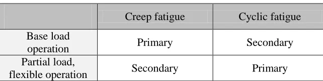
Table 1: Dominant damage mechanism
Creep fatigue Cyclic fatigue
Base load
operation Primary Secondary
Partial load,
flexible operation Secondary Primary
While in the base load operation the damage is predominantly caused by creep processes (above 450°C), in a flexible operation dominates the cyclical fatigue. This change has far-reaching impact for the safety
(maintenance and testing concept) of the power plants:
The components of the main steam system (bends, joint weld of a header), which are highly loaded
by the internal pressure and medium temperature, are affected by the creep fatigue. On the other hand, the thick-walled components of the main steam system are in the focus of cyclic operation.
The damage caused by cyclic fatigue concentrates on the inner surface and affects especially the discontinuities of the components (nozzle inner radii, thickness transitions, groove areas).
The superposition of creep and cyclic fatigue creates an acceleration of the consumption of lifetime,
which forces the plant operator to increased the maintenance effort:
Increased non-destructive testing (NDT) inspection requirements
More downtimes
Premature component replacement
The standard control of the creep fatigue progress by the established method of the non-destructive
It must also be considered that the calculation of cyclic fatigue is based on a non-decoupled multi-parameter problem, see Radaj (1995), and is therefore of limited precision.
The number of changes caused by a flexible and cyclic plant operation shows that the assessment and control of the fatigue state leads to rising efforts and uncertainties in the future.
Figure 2. Component lifetime under dominant cyclic loads, acc. to Mutschler et al. (2013) and Radaj (1995)
In order to find a solution at this point, the research project THERRI was launched. The inclusion of the fracture mechanics evaluated fatigue crack growth (Figure 2) results in a redundant and controllable (by NDT) damage mechanism, which allows safe and efficient plant operation by calculating the remaining service life.
THE FRACTURE MECHANICS ALTERNATIVE
In THERRI, the facture mechanics damage tolerance analysis has been adapted to the needs of the power plant industry. The damage tolerance analysis is a well-proven fracture mechanics assessment method, which is based on the calculation of fatigue crack growth under cyclic loading. Within the damage tolerance analysis an inspection interval is calculated on the basis of the current power station operation. The component state is examined at the beginning and at the end of the inspection interval (NDT). The inspection interval is updated, when the component is free of cracks. This process is repeated until cracks are detected and the fatigue reserves of the component are reached.
The following work steps have to be carried out in detail:
1. Assumption of a crack adet (crack postulate by NDT limiation)
2. Calculation of the critical crack depth acrit and derived maximum allowable crack depth aallow
3. Calculation of fatigue crack growth da/dN for N cyclic load cycles
4. Comparison between the calculated crack depth acal and maximum allowable crack depth aallow
NDT plays an important role in the algorithm of damage tolerance analysis. NDT evaluations had been adapted in THERRI to meet the requirements for thick-walled components for this reason.
The THERRI research project has shown that the fatigue crack growth evaluation has significant advantages compared to a stand-alone fatigue-based assessment (Figure 2). The advantages are:
The calculated fatigue assessment considers the load condition on the inner component surface only
and leads to significantly increasing fatigue values under cyclic loading.
The fatigue crack growth considers the entire component wall. The significant reduction of the stress
range in the component wall results in a damped development of the fatigue crack growth.
The fatigue crack growth is decisively determined by the tensile stresses. So not the full stress ranges
will be used for the crack growth calculation.
In order to fully exploit these advantages, THERRI carried out extensive investigations to determine the fracture mechanics properties of typical power plant steels (X20 CrMoV 12 1).
THERMAL FATIGUE CRACK GROWTH IN POWER PLANT STEELS – JOINT RESEARCH PROJECT THERRI
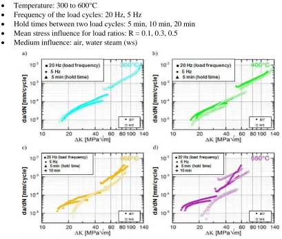
In THERRI, the fracture mechanics characteristics for the heat-resistant martensitic steel X20 CrMoV 12 1 (widely used in German power plants) were intensively examined. The crack growth per load cycle (da/dN) was determined as a function of the following influence parameters:
Temperature: 300 to 600°C
Frequency of the load cycles: 20 Hz, 5 Hz
Hold times between two load cycles: 5 min, 10 min, 20 min
Mean stress influence for load ratios: R = 0.1, 0.3, 0.5
Medium influence: air, water steam (ws)
Figure 3 gives an overview of the identified dependence tendencies of the crack growth propagation rates on temperature, environmental medium and load frequency resp. hold time. Only the measured results for a test temperature below 550°C are shown because we have found that at higher temperatures a relevant interaction of creep and fatigue crack propagation occurs that leads to different dependence tendencies.
Figure 4 shows the comparison of the THERRI experimental data with upper bound crack propagation rate curves of the fracture mechanics standard codes ASME Boiler & Pressure Vessel Code, Section XI (2015) and British Standard BS 7910 (2013). This comparison shows that the THERRI data include considerable evaluation and safety reserves which can be opened up within a damage tolerance analysis. The lifetime potentials that can be achieved by the knowledge of specific fracture mechanics parameters beyond the standard curves are impressively illustrated in Figure 4.
Figure 4. Fatigue crack propagation rate tendencies of X20 CrMoV 12 1, at load ratio R = 0.1
All in Figure 3 and Figure 4 diagrammed measurements were carried out by the THERRI project partner Forschungszentrum Jülich, institute IEK-2, for a load ratio R = 0.1.
SIC – SMART INSPECTION CONCEPT
A modern inspection concept (SIC - Smart Inspection Concept) was derived from the research project
THERRI and summarizes all measures for the determination of an inspection interval required for a safe
damage prevention. This concept fully incorporates the advantages of fatigue crack growth for the
calculation of flexible, load-dependent inspection intervals; see Rieck and Schulz (2015), Rieck et al. (2017).
Starting position
A high fatigue status of the armature is expected by a cyclic operation.
The design analysis cannot prove that the fatigue of the components at the end of the operating time
(25 years) is less than 100%.
There is no method for measuring fatigue caused by cyclic loading. Microstructure imprints measure
creep fatigue only; see Rieck and Schulz (2015).
Necessary measures without SIC
Frequent inspections based on a standard test intervals
In order to assess the chances of continued operation of the components, the SIC concept was decided to apply.
SIC - Definition of the relevant design areas and the NDT positions
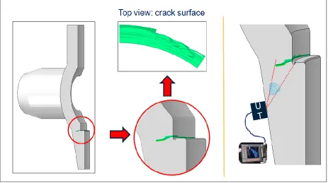
The selection of the NDT locations is determined by the dimensioning relevant areas. This includes all areas which deviate from the basic contour of the sphere, the cylinder or the flat plate and therefore have increased stress values.
The armature is designed as spherical component with nozzles and a valve seat inside. The valve seat and the nozzles edges of the armature are relevant design areas.
Figure 5. Design areas and possible crack positions (XFEM analysis, ABAQUS)
Estimation of the inspection interval
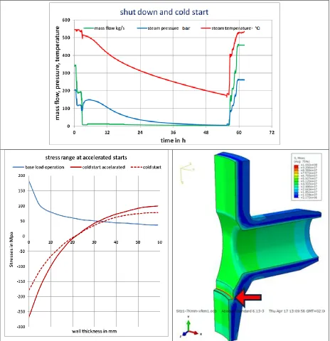
The calculation of the crack growth is based on the fracture mechanics damage tolerance analysis. Before the fracture mechanics calculation, the stress profiles in the component wall were determined for the load case "cold start" (Figure 6, upper part). The lower part of Figure 6 also shows how accelerated starts act on the enlargement of the stress ranges on the component inner wall. In contrast to the fatigue calculation, crack growth involves the entire stress profile over the component wall thickness in the fracture mechanics calculation. The stress ranges in the outer wall areas are significantly reduced and lead to a damped crack growth.
For the crack growth calculation the fracture mechanics material parameters determined in THERRI were used. The starting value for the crack growth calculation was the postulated initial crack depth which relates to the reliably detection limit of the used ultrasonic testing technique (NDT measurement). This value was fixed conservatively with 5 mm.
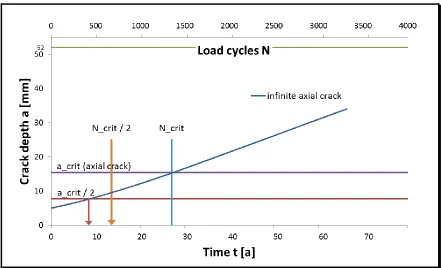
Figure 7. Basic example for a crack growth diagram (Damage Tolerance diagram)
As Figure 7 shows, the maximum allowable inspection interval was determined by the comparison of cyclic crack growth and the maximum allowable crack depth (aallow = acrit / 2) and is about 8 years.
Results
An intelligent inspection concept adapted to the needs of a cyclic operation like SIC can be an essential tool for the economic and safe operation of the components.
By continually updating the maximum allowable inspection interval on the basis of the actual operation mode, the components can be operated up to the point in time when real initial cracks are first detected within the in-service NTD inspection which indicates that the residual lifetime is exploited.
CONCLUSION
The fatigue analysis, which is anchored in the regulations, provides a rough approximation for the lifetime consumption of a component.
The fracture mechanics damage tolerance analysis for the assessment of power plant components represents a real alternative to the established, classical fatigue assessment.
The evaluation of fatigue crack growth answers the question of how long a component can be operated with a postulated crack. On the basis of this additional knowledge, a maximum allowable inspection interval is determined. In this way, cyclic operation with calculable risk is possible and justifiable:
The inspection interval is based on the approximate results of the fatigue analysis which show that
operation with high fatigue values does not directly lead to a spontaneous component failure.
By knowing the maximum allowable inspection interval, significant advantages can be achieved:
The damage mechanism adapted inspection intervals
Reduction of the radiation exposure of the NDT personnel
Exploiting the life time of the component
Evaluation of flexible operation conditions like increasing starting gradients
The damage tolerance analysis evaluates the lifetime period “fatigue crack growth”. This is a powerful tool for safe and effective plant operation.
ACKNOWLEDGEMENTS
The authors wish to thank the German Federal Ministry for Economic Affairs and Energy (Bundesministerium für Wirtschaft und Energie (BMWi)) for financially supporting the joint research project THERRI, contract number 03ET7024A-D. Furthermore, all THERRI project partners are gratefully acknowledged for their intensely and valuably done collaboration, which will be hopefully continued.
REFERENCES
Schlagenhaufer, M. (2010), „Simulation des Dampf-Wasserkreislaufs und der Sicherheitssysteme eines High Performance Light Water Reactors“, M. Schlagenhaufer, KIT SCIENTIFIC REPORTS 7582, Dissertation 2010, ISBN 978-3-86644-661-8
Guelton, E., Fischer, K. (2006), „Festigkeitsanalyse für den Reaktordruckbehälter des High Performance Light Water Reactor(HPLWR)“, FZKA 7270, Institut für Kern- und Energietechnik,
Forschungszentrum Karlsruhe GmbH, Karlsruhe
Mutschler, P., Rieck, D., Sander, M., Schulz, A., Wernicke, R. (2013). “Paradigm Shift from Creep Towards Fatigue Degradation Due to Flexible Thermal Loads” LCF7, Aachen, Germany
Radaj, D., (1995). “Ermüdungsfestigkeit”, Springer
ASME Boiler & Pressure Vessel Code, Section XI, (2015). “Rules For Inservice Inspection Of Nuclear Power Plant Components”, Nonmandatory Appendix A, Analysis Of Flaws
BS 7910, (2013). “Guide to methods for assessing the acceptability of flaws in metallic structures”, British Standards Institution
Rieck, D., Schulz, A., (2015). “THERRI – A Joint Research Project to Meet the Challenges of Power Plant Flexibilisation by a Smart Inspection Concept”, Power-Gen Europe, Amsterdam
Rieck, D., Schulz, A. Czubanowski M., (2017). „Richtlinienentwurf – Schadenstoleranzanalyse im Kraftwerksbereich, Festlegung von Prüfintervallen für dickwandige Kraftwerkskomponenten mittels einer Schadenstoleranzanalyse“, Stand 4/2017