74:8 (2015) 101–105 | www.jurnalteknologi.utm.my | eISSN 2180–3722 |
Jurnal
Teknologi
Full Paper
Z-T
RANSFORM
M
ETHOD FOR
O
PTIMIZATION OF
A
DD
-D
ROP
C
ONFIGURATION
S
YSTEM
Suzairi Daud
*, Kashif Tufail Chaudary, Mahdi Bahadoran, Jalil Ali
Laser Center, Ibnu Sina Institute for Scientific & Industrial Research,
Universiti Teknologi Malaysia, 81310 UTM Johor Bahru, Johor,
Malaysia
Article history
Received 10 October 2014 Received in revised form
10 December 2014 Accepted 13 January 2015
*Corresponding author
[email protected]
Graphical abstract
Abstract
This paper presents the new approaches of optimization the add-drop configuration system by using Z-transform method. Dark soliton was chosen as the input signal and Gaussian beam was chosen as the control signal for the model proposed. The incident light was said to achieve the maximum resonance with the ring resonator when the phase shift,
𝜙 = 2𝜋𝑚. The derivation, analyzation, and optimization of the system are typically very
important especially for the communication technology.
Keywords: Optical solitons, Z-transform method, dark-bright soliton, Gaussian beam
Abstrak
Penerbitan ini mempersembahkan cara terbaru untuk mengoptimumkan sistem penambah-lepasan menggunakan kaedah Z-ubahan. Soliton gelap dipilih sebagai signal masukan dan pancaran Gaussian dipilih sebagai signal pengawal bagi sistem dicadangkan. Cahaya pancaran dikatakan mencapai resonans maksimum dengan
pengalun cincin apabila fasa ubahan, 𝜙 = 2𝜋𝑚. Pembuktian, penganalisisan, dan
pengoptimuman sistem ini sangat penting terutamanya dalam bidang komunikasi.
Kata kunci: Soliton optik, Kaedah Z-ubahan, soliton gelap-cerah, pancaran Gaussian
© 2015 Penerbit UTM Press. All rights reserved
1.0 INTRODUCTION
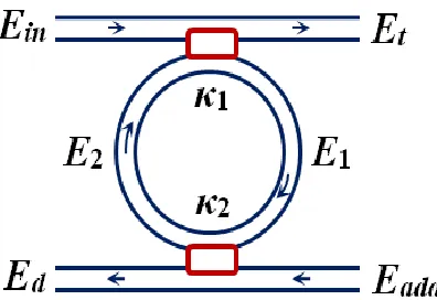
Add-drop configuration system consists of
unidirectional coupling between a ring resonator and nonlinear fibre waveguides [1] as depicted in Figure 1. Four channels of the ring resonator system are marked as input, add, throughput, and drop ports, depicted as
𝐸𝑖𝑛, 𝐸𝑎𝑑𝑑, 𝐸𝑡, and 𝐸𝑑 respectively. When an input
electric field is coupled into the ring waveguide through an external bus waveguide, a positive feedback is induced. The field inside the ring resonator is said to starts build-up [2]. Tuned soliton pulses are obtained using add-drop and PANDA multiplexers.
Figure 1 Add-drop configuration system
1.40 1.45 1.50 1.55 1.60 1.65 1.70 0
3 6 9 12
Wavelength (m)
D
r
op
P
or
t,
|Et
|
2(W)
1.40 1.45 1.50 1.55 1.60 1.65 1.70 0
5 10 15
Wavelength (m)
T
h
r
ou
gh
p
u
t P
or
t,
|Et
|
2
(W)
(a)
2.0 ANALYZATION AND OPTIMIZATION OF
ADD-DROP SYSTEM
Input dark soliton was launched into the system through the input port and controlled by Gaussian beam at the add port respectively. The power
intensities coupled into the system is𝑡 times the input
power for through-path transmission and 𝜅 times the
input power for cross-path transmission [3]. t and κ
are the self-coupling coefficient and cross-coupling coefficient of the waveguide respectively.
𝑡 and 𝜅 are related as [4]:
|2| + |𝑡2|
= 1 (1)
The transmission for one complete roundtrip is represented as:
𝑒𝑥𝑝 (−𝛼𝐿
2
− 𝑗𝑘𝑛𝐿) (2)
The Z-transform parameter is given as [5]:
𝑧−1
= 𝑒𝑥𝑝−𝑗𝑘𝑛𝐿 (3)
where 𝑘𝑛=2𝜋𝜆𝑛𝑒𝑓𝑓 is the propagation constant, 𝜆 is
the wavelength, and 𝑛𝑒𝑓𝑓 is the effective refractive
index of the waveguide.
The transmission optical field 𝐸𝑡at throughput port
is given as [6]:
𝐸𝑡
= [𝑡1+ (−𝜅1)2(𝑡2)(𝑧−1)(𝑎)
· {1 + (𝑡1𝑡2𝑎𝑧−1) + (𝑡1𝑡2𝑎𝑧−1)2
+ ··· (𝑡1𝑡2𝑎𝑧−1)𝑛 }] . 𝐸𝑖𝑛 (4)
By using Taylor’s expansion series, Equation (4) can be simplified as:
𝐸𝑡= [
𝑡1− 𝑡2𝑎𝑧−1
1 − 𝑡1𝑡2𝑎𝑧−1]
· 𝐸𝑖𝑛 (5)
The transmission power, 𝑃𝑡 is then given as [7]:
𝑃𝑡= 𝐸𝑡· 𝐸𝑡 ∗
= 𝑡1
2+ 𝑎2𝑡
2 2− 𝑎𝑡1𝑡2(𝑒−𝑗𝑘𝑛𝐿+ 𝑒𝑗𝑘𝑛𝐿)
1 + 𝑎2𝑡
1 2𝑡2 2− 𝑎𝑡1𝑡2(𝑒−𝑗𝑘𝑛𝐿+ 𝑒𝑗𝑘𝑛𝐿)
· 𝐸𝑖𝑛 2 (6)
By using 𝑒𝑗𝑥= cos(𝑥) + 𝑗 sin(𝑥) and 𝑒−𝑗𝑥= cos (𝑥) −
𝑗 sin(𝑥), Equation (6) becomes:
𝑃𝑡=
𝑡1 2+ 𝑎2𝑡2 2− 2𝑎𝑡1𝑡2cos(𝑘𝑛𝐿)
1 + 𝑎2𝑡
1 2𝑡2 2− 2𝑎𝑡1𝑡2cos(𝑘𝑛𝐿)
· 𝐸𝑖𝑛 2 (7)
The transmission optical field, 𝐸𝑑 at drop port, from
input 𝐸𝑖𝑛is given as [8]:
𝐸𝑑= [−𝜅1𝜅2√𝑎√𝑧−1· {1 + (𝑡1𝑡2𝑎𝑧
−1) + (𝑡
1𝑡2𝑎𝑧−1)2
+ ··· +(𝑡1𝑡2𝑎𝑧−1)𝑛 }] · 𝐸𝑖𝑛
= [−𝜅1𝜅2√𝑎𝑧−1
1 − 𝑡1𝑡2𝑎𝑧−1]
· 𝐸𝑖𝑛 (8)
The transmission power, 𝑃𝑑 is given as [9]:
𝑃𝑑= 𝐸𝑑· 𝐸𝑑 ∗
= 𝑎(1 − 𝑡1 2)(1 − 𝑡2 2)
1 + 𝑎2𝑡
1 2𝑡2 2− 2𝑎𝑡1𝑡2cos(𝑘𝑛𝐿)
· 𝐸𝑖𝑛 2 (9)
The transmission optical field, 𝐸𝑡 at throughput port,
from input 𝐸𝑎𝑑𝑑is given as [10]:
𝐸𝑡= [−𝜅1𝜅2√𝑎√𝑧−1
· {1 + (𝑡1𝑡2𝑎𝑧−1) + (𝑡1𝑡2𝑎𝑧−1)2
+ ··· +(𝑡1𝑡2𝑎𝑧−1)𝑛 }] . 𝐸𝑎𝑑𝑑
= [−𝜅1𝜅2√𝑎𝑧−1
1 − 𝑡1𝑡2𝑎𝑧−1]
· 𝐸𝑎𝑑𝑑 (10)
The transmission power, 𝑃𝑡 is given as [11]:
𝑃𝑡= 𝐸𝑡· 𝐸𝑡 ∗
= 𝑎(1 − 𝑡1
2)(1 − 𝑡
2 2)
1 + 𝑎2𝑡
1 2𝑡2 2− 2𝑎𝑡1𝑡2cos(𝑘𝑛𝐿)
· 𝐸𝑎𝑑𝑑 2 (11)
The transmission optical field 𝐸𝑑 at drop port from
input 𝐸𝑎𝑑𝑑 is given as [10]:
𝐸𝑑= [𝑡2+ (−𝜅2)2(𝑡1)(𝑧−1)(𝑎)
· {1 + (𝑡1𝑡2𝑎𝑧−1) + (𝑡1𝑡2𝑎𝑧−1)2
+ ··· +(𝑡1𝑡2𝑎𝑧−1)𝑛 }] · 𝐸𝑎𝑑𝑑
= [𝑡2− 𝑡1𝑎𝑧
−1
1 − 𝑡1𝑡2𝑎𝑧−1]
· 𝐸𝑎𝑑𝑑 (12)
The transmission power, 𝑃𝑑 is given as [11]:
𝑃𝑑= 𝐸𝑑· 𝐸𝑑 ∗
= 𝑡2
2+ 𝑎2𝑡
1 2− 2𝑎𝑡1𝑡2cos(𝑘𝑛𝐿)
1 + 𝑎2𝑡
12𝑡22− 2𝑎𝑡1𝑡2cos(𝑘𝑛𝐿)
· 𝐸𝑎𝑑𝑑 2 (13)
[𝐸𝑡
𝐸𝑑]
= 𝑆𝑅[𝐸𝐸𝑖𝑛
𝑎𝑑𝑑] (14)
𝑆𝑅 is given as:
𝑆𝑅= [𝐻𝐻11 𝐻12
21 𝐻22]
=
[
[𝑡1− 𝑡2𝑎𝑧−1
1 − 𝑡1𝑡2𝑎𝑧−1] [
−𝜅1𝜅22√𝑎𝑧−1
1 − 𝑡1𝑡2𝑎𝑧−1]
[−𝜅1𝜅2√𝑎𝑧−1
1 − 𝑡1𝑡2𝑎𝑧−1] [
𝑡2− 𝑡1𝑎𝑧−1
1 − 𝑡1𝑡2𝑎𝑧−1]]
(15)
Hence,
[𝐸𝑡
𝐸𝑑]
=
[
[𝑡1− 𝑡2𝑎𝑧−1
1 − 𝑡1𝑡2𝑎𝑧−1] [
−𝜅1𝜅22√𝑎𝑧−1
1 − 𝑡1𝑡2𝑎𝑧−1]
[−𝜅1𝜅2√𝑎𝑧−1
1 − 𝑡1𝑡2𝑎𝑧−1] [
𝑡2− 𝑡1𝑎𝑧−1
1 − 𝑡1𝑡2𝑎𝑧−1]]
[𝐸𝐸𝑖𝑛
𝑎𝑑𝑑] (16)
By solving the matrix, Equations (10) and (12) becomes:
𝐸𝑡= 𝐸𝑡ℎ𝑟𝑜𝑢𝑔ℎ𝑝𝑢𝑡
= [𝑡1− 𝑡2𝑎𝑧−1
1 − 𝑡1𝑡2𝑎𝑧−1] · 𝐸𝑖1+ [
−𝜅1𝜅22√𝑎𝑧−1
1 − 𝑡1𝑡2𝑎𝑧−1]
· 𝐸𝑎𝑑𝑑 (17)
and
𝐸𝑑= 𝐸𝑑𝑟𝑜𝑝
= [−𝜅1𝜅2√𝑎𝑧−1
1 − 𝑡1𝑡2𝑎𝑧−1] · 𝐸𝑖1+ [
𝑡2− 𝑡1𝑎𝑧−1
1 − 𝑡1𝑡2𝑎𝑧−1]
· 𝐸𝑎𝑑𝑑 (18)
The interaction between the input optical field, 𝐸𝑖𝑛
and control signal, 𝐸𝑎𝑑𝑑 occurs inside the ring
resonator waveguide. The circulated optical fields,
𝐸1 and 𝐸2 inside the system can be written as follows
[13].
Circulated field 𝐸11, from input field 𝐸𝑖𝑛is given as:
𝐸11= [−𝜅1√𝑎𝑧−1· {1 + (𝑡1𝑡2𝑎𝑧
−1) + (𝑡
1𝑡2𝑎𝑧−1)2
+ ··· +(𝑡1𝑡2𝑎𝑧−1)𝑛 }] · 𝐸𝑖𝑛
= [ −𝜅1√𝑎𝑧−1
1 − 𝑡1𝑡2𝑎𝑧−1]
· 𝐸𝑖𝑛 (19)
Similarly, circulated field 𝐸12 from input field 𝐸𝑎𝑑𝑑 can
be expressed as:
𝐸12= [−𝑡1𝜅2𝑎𝑧−1· {1 + (𝑡1𝑡2𝑎𝑧
−1) + (𝑡
1𝑡2𝑎𝑧−1)2
+ ··· +(𝑡1𝑡2𝑎𝑧−1)𝑛 }] · 𝐸𝑎𝑑𝑑
= [ −𝑡1𝜅2𝑎𝑧
−1
1 − 𝑡1𝑡2𝑎𝑧−1]
· 𝐸𝑎𝑑𝑑 (20)
Circulated field 𝐸21 from input field 𝐸𝑖𝑛 can be
expressed as:
𝐸21= [−𝑡2𝜅1𝑎𝑧−1· {1 + (𝑡1𝑡2𝑎𝑧
−1) + (𝑡
1𝑡2𝑎𝑧−1)2
+ ··· +(𝑡1𝑡2𝑎𝑧−1)𝑛 }] · 𝐸𝑖𝑛
= [ −𝑡2𝜅1𝑎𝑧−1
1 − 𝑡1𝑡2𝑎𝑧−1]
· 𝐸𝑖𝑛 (21)
Similarly, circulated field 𝐸22 from input field 𝐸𝑎𝑑𝑑 is
given as:
𝐸22= [−𝜅2√𝑎𝑧−1{1 + (𝑡1𝑡2𝑎𝑧
−1) + (𝑡
1𝑡2𝑎𝑧−1)2
+ ··· +(𝑡1𝑡2𝑎𝑧−1)𝑛 }] · 𝐸𝑎𝑑𝑑
= [ −𝜅2√𝑎𝑧−1
1 − 𝑡1𝑡2𝑎𝑧−1]
· 𝐸𝑎𝑑𝑑 (22)
Hence, the transmission fields at 𝐸1 and 𝐸2 are given
as:
𝐸1= [
−𝜅1√𝑎𝑧−1
1 − 𝑡1𝑡2𝑎𝑧−1] · 𝐸𝑖𝑛+ [
−𝑡1𝜅2𝑎𝑧−1
1 − 𝑡1𝑡2𝑎𝑧−1]
· 𝐸𝑎𝑑𝑑 (23)
and
𝐸2= [
−𝑡2𝜅1𝑎𝑧−1
1 − 𝑡1𝑡2𝑎𝑧−1] · 𝐸𝑖𝑛+ [
−𝜅2√𝑎𝑧−1
1 − 𝑡1𝑡2𝑎𝑧−1]
· 𝐸𝑎𝑑𝑑 (24)
Finally, the output fields at throughput and drop ports are given as:
𝐸𝑡= [𝑡1− 𝑡2𝑎𝑧
−1
1 − 𝑡1𝑡2𝑎𝑧−1] · 𝐸𝑖𝑛+ [
−𝜅1𝜅22√𝑎𝑧−1
1 − 𝑡1𝑡2𝑎𝑧−1]
· 𝐸𝑎𝑑𝑑 (25)
and
𝐸𝑑= [
−𝜅1𝜅2√𝑎𝑧−1
1 − 𝑡1𝑡2𝑎𝑧−1] · 𝐸𝑖𝑛+ [
𝑡2− 𝑡1𝑎𝑧−1
1 − 𝑡1𝑡2𝑎𝑧−1]
· 𝐸𝑎𝑑𝑑 (26)
3.0 RESULTS AND DISCUSSION
Add-drop system is very useful for filtering and cancelling the chaotic signals, which is important indeed for the communication and security link technologies. Dark soliton pulse with 3.50 W input power is launched into the system through the input port and Gaussian beam with 1.22 W input power is injected through the add port. In operation, a 34 μm ring resonator radius is used for the proposed system. By using InGaAsP/InP fibre waveguide [14], the
waveguide wave coefficient, 𝛼 and the intensity
insertion loss coefficient, 𝛾 of the coupler are 𝛼= 0.05
dB km-1 and 𝛾 = 0.1 respectively. Two fibre couplers
connected with both bus waveguides, marked with
𝜅1 and 𝜅2 respectively as depicted in the schematic
diagram shown in Figure 1. The coupling coefficients,
𝜅1 and 𝜅2 values are set at 𝜅1 = 0.55 and 𝜅2 = 0.35
respectively. The results for output fields at
throughput and drop ports, 𝐸𝑡 and 𝐸𝑑 of the system
were examined.
The interaction between dark soliton and Gaussian beam within the system are shown in Figure 2 where
Figure 2(a) is the output signal at drop port, Ed and
Figure 2(b) is the signal generated at the throughput
port, Et of the system. The highest output power
generated were 10.798 and 13.944 W for 𝐸𝑑 and 𝐸𝑡
ports respectively. The set-up in Figure 1 is then modified by adding a PANDA ring to the model designed. Due to the dynamical behaviour of the PANDA system, the signal flow through the right and left sides of the nanorings results the large amplification of the travelling optical signals. At the
circulating points 𝐸1 and 𝐸2, the signals are tuned in
the ring resonator due to resonance [15]. The circulating process within the ring results the high output signals of the system. The signals filtering and cancelling process of the add-drop system results the single signal as the outputs as depicted in Figure 3. Those input and control signals were continuous to propagate into the system and caused the optical collisions between both signals within ring waveguides. Figure 3 shows the output signals generated at throughput port where Figure 3(a) shows the output signal generated without filtering process and Figure 3(b) shows the signal generated after add-drop filtering process take placed. It can see that the maximum power generated increased up to 18.834 W instead of 13.944 W without the existence of the PANDA system. This is due to the intensity build-up factor within both right and left nanorings [16].
Figure 2 Output signal of the add-drop system at the (a) drop port (b) throughput port
Figure 3 Generated signals at throughput port of the system where (a) without filtering process (b) after filtering process
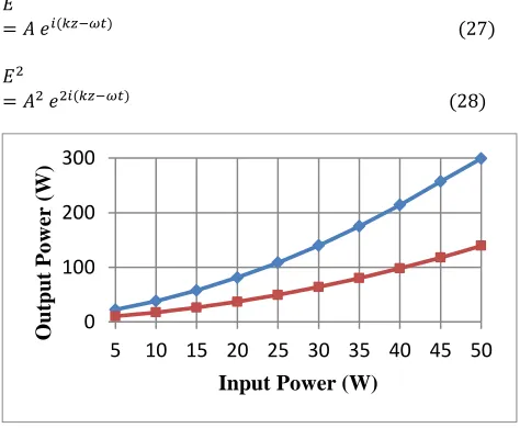
As discussed, the system consists of an input and an add ports, where these two parameters influence the performance of the system at the circulating fields as well as output fields characteristics. The input power is one of very important parameter which will give big effects towards the performance of the system. The input power values are varied from 5 to 50 W respectively. The power value of the
control signal is fixed at 𝐸𝑎𝑑𝑑 = 2 W. It is shown that
the values of output power increases with increase
of the input power, 𝐸𝑖𝑛 as in Figure 4. From the graph
plotted, it can be seen that the output power of the system increases exponentially with the increase in
the values of input power, 𝐸𝑖𝑛. This is significantly
related from the theoretical calculation where:
𝐸
= 𝐴 𝑒𝑖(𝑘𝑧−𝜔𝑡) (27)
𝐸2
= 𝐴2 𝑒2𝑖(𝑘𝑧−𝜔𝑡) (28)
Figure 4 Relationship between input and output power at throughput and drop ports of the system
4.0 CONCLUSION
The development and analyzation of the add-drop configuration system using Z-transform method have been done. The meaningful of the optical solitons channel trapping toward the communication technology and the used of the PANDA system collaborated with add-drop configuration system have been investigated thoroughly. It is proved that
1.40 1.45 1.50 1.55 1.60 1.65 1.70
0 3 6 9 12
Wavelength (m)
D r op P or t , |E t | 2( W)
1.40 1.45 1.50 1.55 1.60 1.65 1.70
0 5 10 15
Wavelength (m)
T h r ou gh p u t P or t , |E t | 2( W) (a) (b)
1.40 1.45 1.50 1.55 1.60 1.65 1.70 0
5 10 15 20
Wavelength (m)
T h ro u gh p u t P or t, |Et | 2(W)
1.40 1.45 1.50 1.55 1.60 1.65 1.70 0
5 10 15 20
Wavelength (m)
T h ro u gh p u t P or t, |Et | 2(W) (a) (b) 0 100 200 300
5 10 15 20 25 30 35 40 45 50
O utput P o w er ( W)
the value of input signal of the system giving a big effect towards the system performance.
Acknowledgement
The authors like to acknowledge Laser Center, Ibnu Sina Institute for Scientific & Industrial Research, Universiti Teknologi Malaysia for supporting this research.
References
[1] Kivshar, Y. S. and Agrawal, G. 2003. Optical Solitons: From
Fibers to Photonic Cristals. Academic Press.
[2] Little, B. E., Chu, S. T., Haus, H. A., Foresi, J. and Laine, J. P. 1997. Microring Resonator Channel Dropping Filters.
Journal of Lightwave Technology. 15(6): 998-1005.
[3] Minzioni, P., Bragheri, F., Liberale, C., Di Fabrizio, E. and Cristiani, I. 2008. A Novel Approach to Fiber-Optic Tweezers: Numerical Analysis of the Trapping Efficiency. IEEE Journal of Selected Topics in Quantum Electronics. 14(1): 151-157.
[4] Yupapin, P. P. 2010. Generalized Quantum Key Distribution via Microring Resonator for Mobile Telephone Networks. Optics Letter. 121(5): 422-425.
[5] Absil, P. P., Hryniewicz, J. V., Little, B. E., Wilson, R. A., Joneckis, L. G. and Ho, P. T. 2000. Compact Microring Notch Filters. IEEE Photonics Technology Letters. 12(4): 398-400.
[6] Aziz, M. S., Suwanpayak, N., Jalil, M. A., Jomtarak, R., Saktioto, T., Ali, J. and Yupapin, P. P. 2012. Gold Nanoparticle Trapping and Delivery for Therapeutic Applications. International Journal of Nanomedicine. 7: 11-17.
[7] Jalil, M. A., Innate, K., Suwanpayak, N., Yupapin, P. P. and Ali, J. 2011. Molecular Diagnosis Using Multi Drug Delivery
Network and Stability. Artificial Cells, Blood Substitutes,
and Biotechnology. 39(6): 357-365.
[8] Mitatha, S., Putthacharoen, R. and Yupapin, P. P. 2012. THz Frequency Bands Generation for Radio-Over-Fiber Systems. International Journal for Light and Electron
Optics. 123(11): 974-977.
[9] Mitatha, S., Putthacharoen, R. and Yupapin, P. P. 2012. THz Frequency Bands Generation for Radio-Over-Fiber Systems. International Journal for Light and Electron
Optics. 123(11): 974-977.
[10] Daud, S., Ueamanapong, S., Srithanachai, I., Poyai, A., Niemcharoen, S., Ali, J., and Yupapin, P. P. 2012. Particle Accelerator Using Optical Tweezer for Photodetector Performance Improvement. IEEE Transaction on
Nanotechnology. 11: 1087-1092.
[11] Van Mameren, J., Wuite, G. J. L. and Heller, I. 2011. Introduction to Optical Tweezers: Background, System Designs, and Commercial Solutions. Applied Optics. 1-20. [12] Poon, J., Scheuer, J., Mookherjea, S., Paloczi, G. T.,
Huang, Y. and Yariv, A. 2004. Matrix Analysis of Microring Coupled-Resonator Optical Waveguides. Opt. Express. 12(1): 90-103.
[13] Wen J. L., Bo T., Tao X., Kun S. and Yan J. 2010. Bright and Dark Solitons in the Normal Dispersion Regime on Inhomogeneous Optical Fibers: Soliton Interaction and Soliton Control. Annals of Physics. 32: 1633-1643.
[14] Daud, S., Ueamanapong, S., Srithanachai, I., Poyai, A., Niemcharoen, S., Ali, J., and Yupapin, P. P. 2012. Particle Accelerator Using Optical Tweezer for Photodetector Performance Improvement. IEEE Transaction on
Nanotechnology. 11(6): 1087-1092.
[15] Aziz, M. S., Daud, S., Bahadoran, M., Ali, J., Yupapin, P. P. 2013. Light Pulse in a Modified Add-Drop Optical Filter for Optical Tweezers Generation. Journal of Nonlinear
Optical Physics & Materials. 21(4): 1250047.