Communications
Installation
System
Endeavor
™
Notice
Every effort has been made to ensure that the information in this book is complete and accurate at the time of printing. However, information is subject to change.
Federal Communications Commission (FCC) Interference Notice
This equipment has been tested and found to comply with the limits of a Class A or a Class B digital device, pursuant to Part 15 of FCC rules. For additional information on FCC regulations, see “Federal Communications Commission (FCC) Interference Information” in the PARTNER Endeavor Communications System Programming
and Use guide.
Canadian Emissions Requirements
This digital apparatus does not exceed the Class A or the Class B limits for radio noise emissions from digital apparatus set out in the Radio Interference Regulations of the Industry Canada (IC). For additional IC information, see “IC Notification and Repair Information” in the PARTNER Endeavor Communications System Programming
and Use guide.
Le present appareil numerique n’emet pas de bruits radioelectriques depassant les limites applicables aux appareils numeriques de la Classe A ou de la Classe B prescrites dans le Reglement sur le brouillage radioelectrique edicte par le ministere des Industrie Canada. Vous trouverez des renseignements complémitaires dans cette section: “IC Notification and Repair Information” de PARTNER Endeavor Communications System Programming and Use
guide.
Security
Toll fraud, the unauthorized use of your telecommunications system by an unauthorized party (for example, persons other than your company’s employees, agents, subcontractors, or persons working on your company’s behalf) can result in substantial additional charges for your telecommunications services. You are responsible for the security of your system. There may be a risk of toll fraud associated with your telecommunications system. You are responsible for programming and configuring your equipment to prevent unauthorized use. Your system manager should read all documents provided with this product to fully understand the features that can introduce the risk of toll fraud and the steps that can be taken to reduce that risk. Lucent Technologies does not warrant that this product is immune from or will prevent unauthorized use of common-carrier telecommunication services or facilities accessed through or connected to it. Lucent Technologies will not be responsible for any charges that result from such unauthorized use. If you suspect you are being victimized by toll fraud and you need technical support or assistance, call the Lucent Technologies National Customer Care Center at 1-800-721-7071.
Trademarks
Magic on Hold, MERLIN, MLS-34D, MLS-18D, MLS-12D, MLS-12, MLS-6, PARTNER, PARTNER MAIL, PARTNER MAIL VS, PassageWay, SYSTIMAX, and TransTalk are registered trademarks of Lucent Technologies. PARTNER Endeavor is a trademark of Lucent Technologies. Microsoft is a registered trademark and Windows is a trademark of Microsoft Corporation. The SoundStation is a registered trademark of Polycom, Inc.
Warranty
Lucent Technologies provides a limited warranty for this product. Refer to “Lucent Technologies Limited Warranty and Limitation of Liability” in Appendix B of of the PARTNER Endeavor Communications System Programming
and Use guide.
Ordering Information
The order number for this book is 518-458-101. To order additional books, call 800-457-1235 in the continental U.S. or 765-361-5353 outside the continental U.S. For information about ordering other system reference materials, replacement parts, accessories, and other compatible equipment, refer to “Product Ordering Information” in Appendix B of the PARTNER Endeavor Communications System Programming and Use guide.
Support Telephone Number
In the continental U.S., Lucent Technologies provides a toll-free customer hotline 24 hours a day. Call the hotline at 800-721-7071 or your Lucent Technologies Authorized Dealer, if you need assistance when programming or using your system. Consultation charges may apply.
Important Safety Instructions
The following list provides basic safety precautions that should always be followed when using your telephone equipment:
1. Read and understand all instructions.
2. Follow all warnings and instructions marked on the product.
3. Unplug all telephone connections before cleaning. DO NOT use liquid cleaners or aerosol cleaners. Use a damp cloth for cleaning.
4. This product should be serviced by (or taken to) a qualified repair center when service or repair work is required.
5. DO NOT use this product near water—for example, in a wet basement location.
6. DO NOT place this product on an unstable cart, stand, or table.
7. Never push objects of any kind into slots or openings as they may touch dangerous voltage points or short out parts that could result in a risk of fire or electric shock. Never spill liquid of any kind on the product.
8. DO NOT use the telephone to report a gas leak in the vicinity of the leak.
9. The product is provided with a three-wire grounding type plug. This is a safety feature. DO NOT defeat the safety purpose of the grounding type plug. DO NOT staple or otherwise attach the power supply cord to building surfaces.
!
CAUTION:
DO NOT block or cover the ventilation slots or openings. They prevent the product from overheating. DO NOT place the product in a separate enclosure unless proper ventilation is provided. DO NOT place the product flat on a surface. The control unit must be wall-mounted.
Additional Safety Instructions for Installation Personnel
1. DO NOT install telephone wiring during a lightning storm.
2. DO NOT install telephone jacks in a wet location, unless the jack is specifically designed for wet locations.
3. Never touch uninsulated telephone wires or terminals, unless the telephone line has been disconnected at the network interface.
4. Use caution when installing or modifying telephone lines.
5. The control unit must be securely wall-mounted.
!
CAUTION:
If any wiring from the extension jacks is run from the building premises, you must install Lucent Technologies IROB protectors (see “Requirements for Out-of-Building Installations” at the end of this book).
!
CAUTION:
Use only Lucent Technologies-manufactured PARTNER Endeavor or PARTNER MAIL VS modules in the PARTNER Endeavor Communications System.
Contents
Installation
■ Overview 1
■ A Sample System Setup 1
■ Required Parts 4
■ Installation Guidelines 5
— Telephones and Devices 5
— Combination Extensions 7
■ Installation Procedures 9
— Wall-Mounting a Stand-Alone
PARTNER Endeavor 362 Processor Module 9
— Wall-Mounting a 2-Slot Carrier and Modules 10 — Wall-Mounting a 5-Slot Carrier and Modules 13 — Inserting Batteries in the PARTNER Endeavor
362 Processor Module 15
— Using the PC Card and Powering Up the System 18
— Connecting Lines and Extensions 20
— Connecting and Testing Telephones 24
— Music-On-Hold Audio Source 25
— Connecting a PARTNER-CA48 Call Assistant
Intercom Autodialer 26
■ Equipment Upgrades 27
— Replacing System Modules 27
■ Specifications 35
— Capacities 35
— Dimensions and Weights (approx.) 35
Installation
Overview
This guide explains how to install the PARTNER Endeavor™ Communications System. This guide begins with a sample system setup, then shows the components you need to install the system and gives general guidelines to consider before installation. Next, it provides step-by-step instructions for connecting and testing the components for initial installation and upgrades. Finally, it lists important system specifications. You should ensure that your installation meets all electrical and environmental requirements.
If your company already has modular jacks for all outside lines and extensions, you may be able to use the existing wiring to install the system hardware and to connect telephones to the system yourself. To have a Lucent Technologies service technician install and customize your system or change existing wiring, call 800-247-7000 (in the continental U.S. only), or call your Lucent Technologies Representative or local Authorized Dealer.
After installation, refer to the PARTNER Endeavor Communications System Programming and Use guide for programming instructions.
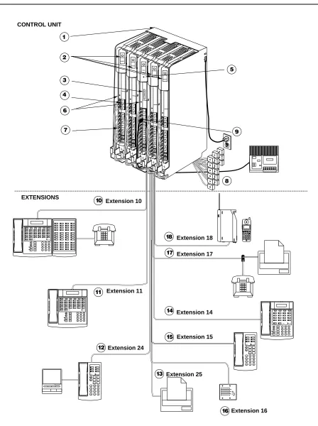
A Sample System Setup
1. 5-Slot Carrier. The carrier channels power to the
system and connects the system modules.
2. 362EC expansion modules. Each 362EC expansion
module has jacks for three lines and eight extensions. NOTE:
A 362EC expansion module can only be used with a PARTNER Endeavor 362 processor.
3. PARTNER Endeavor 362 processor module. The
processor module contains the software that provides the system’s features, and has jacks for three lines and eight extensions. It also has a Music-On-Hold jack.
4. Line Jacks. The top three jacks on the Endeavor and
362EC expansion modules connect to outside telephone lines.
5. Grounding Screw. Attaches a #12 AWG on a #14
AWG solid copper wire to an approved earth ground.
6. Power LED. The power LED lights when the module is
receiving power.
7. Extension Jacks. The bottom eight jacks on the
modules connect inside wiring for telephones and other telecommunications equipment. The top six station ports support only ETR devices, and the bottom two support both ETR and Tip Ring devices.
8. Network Interface Jacks. These jacks provide access
to telephone lines from a local telephone company. Each outside line is connected to the system by plugging one end of the line cord into one of these jacks, and the other end into a line jack in the control unit.
9. MUSIC-ON-HOLD Jack. Lucent Technologies’ Magic-
on-Hold is connected to this jack to provide customized music and messages for callers on hold. Other types of audio equipment (including a CD player, cassette player or stereo receiver) can be connected using an audio cord with an RCA phono plug (not supplied).
For more information, see “Music-On-Hold Audio Source” later in this guide.
10. Extension 10: These devices are connected.
■ PARTNER Endeavor-34D Display Phone.
Typically, the receptionist at extension 10 has a PARTNER Endeavor-34D display phone like the one shown here. The display shows the time, dialed numbers, duration of calls, and programming messages.
■ PARTNER-CA48 Call Assistant Intercom
Autodialer. An Intercom Autodialer is connected to
the phone to dial extensions and transfer calls to them with one touch and to see which extensions are busy.
■ Standard Touch-Tone Phone. During a power
failure, the PARTNER Endeavor-34D phone on extension 10 will not work, but the receptionist can use the standard phone to place calls on line 1.
11. Extension 11: PARTNER Endeavor-34D Display Phone. Another PARTNER Endeavor-34D is connected
to programming extension 11. You can program the system from this extension, leaving the receptionist at extension 10 free to handle calls.
12. Extension 24: PARTNER Endeavor-6 Phone and Answering Machine. A PARTNER Endeavor-6 phone
with standard answering machine is connected to this extension.
13. Extension 25: Fax. With the exception of headphones,
auxiliary equipment works only on Tip Ring ports (the bottom two ports of the PARTNER Endeavor 362 processor or 362EC expansion module). Because headphones do not require a ring, they can be plugged into any port.
14. Extension 14: PARTNER Endeavor-18D Display Phone. This is the doorphone alert extension. When
someone presses the doorphone button, this phone signals and the user can press a button on the phone to release the doorlock.
15. Extension 15: A PARTNER Endeavor-6 phone is
connected to this extension.
16. Extension 16: Doorphone. A doorphone is installed at
the building entrance. When someone presses the button on the doorphone, the designated extensions signal. Extension 14 is the doorphone alert extension. Doorphones should not be connected to ETR-only ports since doorphones rely on receiving a forward
disconnect signal to disconnect a call.
17. Extension 17: Fax Machine and Standard Phone. A
fax machine and standard phone share this extension. This lets you have the use of another phone when the fax machine is idle. Standard phones and auxiliary equipment can be used only in the bottom two Tip Ring ports (the exception to this is that headphones can be plugged into any port since they do not require a ring).
18. Extension 18: MDW 9030P Pocketphone. This
A Sample System Setup 10 14 12 15 13 17 Extension 24 Extension 25 Extension 14 Extension 15 Extension 17
18 Extension 18
EXTENSIONS PUSH Feature ConfMic HFAI Hold Spkr IntercomIntercom + – Transfr ABC 2 DEF 3 1 JKL 5 MNO 6 TUV 8WXYZ 9 0 GHI 4 PQRS 7 * # Message Ext. POWER RADIO PASS
AB234
6
5
MSG212555ON1212 78 CD 1 TransTalk On/Off Feat/P ConfGHI PQRS OPER Trans Hold Redial 12 4JKL
ABC3DEF 56MNO
TUV 8 0 WXYZ 9 7 Mute Extension 10 Feature Intercom ABC 2DEF 3 1 + –Conf JKL
5MNO 6 TUV 8WXYZ 9 Transfr Mic HFAI Hold 0 GHI 4 PQRS 7 * # Spkr Intercom Message Ext.
11 Extension 11
Feature Intercom
+ –Conf JKLMNO
Transfr Mic HFAI Hold GHI 4 * ABC 2DEF 3 1 5 6 TUV 8WXYZ 9 0 PQRS 7 # Spkr Intercom Message Ext. + – Transfr ABC 2 DEF 3 1 JKL 5MNO 6 TUV 8WXYZ 9 0 GHI 4 PQRS 7 * # Message Ext. Transfr Feature Intercom ABC 2DEF 3 1 + –Conf JKL
Required Parts
You may have multiple system component packages; Figure 2 shows the package contents. Check your packages to be sure you have the parts shown here (if not, call for support as instructed on the inside front cover of this guide).
NOTE: NOTE:
The Backup/Restore PC Card is optional for the PARTNER Endeavor 362 processor and it can be purchased separately.
Figure 2. Required Parts
AC Power Cord
Cover Endeavor Processor
Module
AAA Alkaline Batteries
PARTNER Endeavor Communications System Processor Module
7-foot Line Cords
5-Slot Carrier
362EC Module
7-foot Line Cords
362EC Module
PARTNER Plus
5-Slot Carrier
#8-15 x 11/2"
Phillips® Sheet
Metal Screws
#4 x 3/4"
Panhead Sheet Metal
Screws
#8-15 x 31/2"
PhillipsPanhead Screw Battery Door
Cover
2-Slot Carrier
2-Slot Carrier
COMBO COMBO
COMBO COMBO
MUSIC ONHOLD
Installation Guidelines
For a 5-Slot Carrier, you will need to obtain four #12 screws of the appropriate type for the wall and weight of the control unit (a control unit with four 362EC expansion modules and a processor module weighs approximately 31 pounds or 14 kilograms). The weight of other configurations may vary slightly.
In addition, order the following, if needed, before installation:
■ Modular telephone cords to connect the extension jacks in the control unit to the modular connecting blocks for extensions in the equipment room. ■ Short telephone cords or wall plates to wall mount PARTNER
Endeavor-model phones. ■ 355A/355AF adapter.
Refer to “Product Ordering Information” in Appendix B of the PARTNER Endeavor Communications System Programming and Use guide for ordering instructions.
The PARTNER Endeavor 362 processor module and the 362EC expansion modules support the Caller ID feature. These modules are required to provide Caller ID information on system display phones. You must subscribe to Caller ID service from your local telephone company (if it is available), and connect any lines associated with this service to the line jacks on the 362 processor module or the 362EC expansion module.
NOTE:
A system display phone is required for programming at extension 10 and/or 11. If you have any 34-button phones in the system, you must use a 34-button display phone to program, since an 18-button phone cannot be used to program a 34-button phone.
Installation Guidelines
Telephones and Devices
You can connect the following telephones and devices to the system:
■ PARTNER Endeavor-model, MDC 9000, and TransTalk® 9000-series
System Phones. System phones require at least two-pair wiring and are compatible with Lucent Technologies 4-pair SYSTIMAX® wiring.
■ Call Assistant Intercom Autodialers with Busy Indication
NOTE:
With the exception of headphones, standard phones and auxiliary equipment work only on Tip Ring ports (the bottom two ports of the PARTNER Endeavor 362 processor module or 362EC expansion module). Because headphones do not require a ring, they can be plugged into any port.
■ Industry-Standard Devices. Industry-standard devices (including standard phones) require one-pair mounting cords; Lucent Technologies D2R mounting cords are recommended.
— Standard Phones. Connect standard touch-tone or rotary dial phones to the system. You can connect a standard phone either alone or combined with a system phone. For more information, see
‘‘Combination Extensions’’ on page 7. Standard phones can be used to make calls when plugged into any port of the PARTNER Endeavor 362 processor module or 362EC expansion module. Standard phones, however, will ring only on Tip Ring ports, which are the bottom two ports.
— Power Failure Operation. During a power failure, system phones will not work because they require power to operate. If you connect a standard phone to the first extension on the PARTNER Endeavor 362 processor module, however, users can place and answer outside calls on the first line.
— Hotlines. A hotline extension should be connected to a standard phone, rather than a system telephone, but it can ring any type of phone. Standard phones can be used to make calls when plugged into any port of the PARTNER Endeavor 362 processor module or 362EC expansion module. Standard phones, however, will ring only on Tip Ring ports, which are the bottom two ports.
For the message-waiting capability, you must connect standard phones with LED-compatible message-waiting lights to a PARTNER Endeavor 362 processor module or the 362EC expansion modules. This message-waiting capability does not work with standard phones with neon-type
message-waiting lights.
— Auxiliary Equipment. There are a variety of ways to set up fax machines, modems, and answering machines to work with the system. See Chapter 4 in the PARTNER Endeavor Communications System Programming and Use guide for advice on using this equipment. To connect a telephone and a standard device on the same extension, see ‘‘Combination Extensions’’ on page 7. With the exception of
Installation Guidelines
■ Doorphones. Doorphones should not be connected to an ETR-only port since doorphones rely on receiving a forward disconnect signal to
disconnect a call. Connect doorphones to T/R ports, which are the bottom two ports of the PARTNER Endeavor 362 processor module or 362EC expansion module.
■ Voice Messaging Systems. The system supports the following voice messaging systems:
— PARTNER Voice Messaging PC Card. For more information on using this voice messaging system, see the PARTNER Voice Messaging PC Card Installation, Programming, and Use guide.
— PARTNER MAIL VS® System. This device resides in the control unit. — PARTNER MAIL® System. This device connects to the system through
either 2, 4, or 6 extension jacks. Connect to the bottom two ports of the PARTNER Endeavor 362 processor or any 362EC expansion module. ■ In-Range Out-of-Building Protectors. To prevent damage from lightning,
installing phones or other standard devices (such as a doorphone) in a location other than the building where the control unit is installed requires Lucent Technologies In-Range Out-of-Building (IROB) protectors. (IROBs must be installed by a qualified technician.) With the exception of
headphones, standard phones and auxiliary equipment work only on Tip Ring ports (the bottom two ports of the PARTNER Endeavor 362 processor or 362EC expansion module). Because headphones do not require a ring, they can be plugged into any port.
Combination Extensions
You can connect a standard device (such as a standard phone or an answering machine) so that it is on an extension by itself, or so that it shares an extension with another piece of equipment (either another standard device or a system phone). An extension with two devices connected to it is called a combination extension. (If you combine a standard phone and a system phone on one extension, you may want to turn off the standard phone’s ringer during normal use.)
NOTE:
Standard phones, combination extensions, and auxiliary equipment work only on Tip Ring ports (the bottom two ports of the PARTNER Endeavor 362 processor or 362EC expansion module). Because headphones do not require a ring, they can be plugged into any port.
NOTE:
The Call Assistant Intercom Autodialer is not regarded as a standard device. This means you can connect a standard device to a system phone that also has an Intercom Autodialer installed.
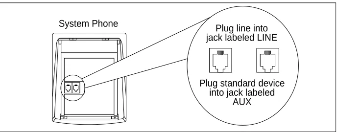
PARTNER Endeavor-model system phones have a built-in auxiliary jack so you can connect a standard device directly to the phone without using a bridging adapter (see “Using a Direct Connection” below). If your phone does not have a built-in auxiliary jack or if you want to connect two standard devices together, you must use a Lucent Technologies 267F2 Bridging Adapter (see “Using a Bridging Adapter” below).
Using a Direct Connection
Figure 3 shows how to connect a standard device directly to a system phone, using the phone’s built-in auxiliary jack. (Figure 3 is for illustration purposes only; the placement of the jacks on your phone may differ.)
Using a Bridging Adapter
Figure 4 shows how to connect a system phone and a standard device or two standard devices using a Lucent Technologies 267F2 Bridging Adapter. This adapter can be ordered separately.
Figure 3. Combination Extension Using Direct Connection
Figure 4. Combination Extension Using Bridging Adapter Plug line into jack labeled LINE System Phone
Plug standard device into jack labeled
AUX
Lucent Technologies
267F2
Adapter
Wall Jack
Standard Device Only
Installation Procedures
Installation Procedures
Before installing the system, be sure you read the safety instructions in the front of this guide.
The PARTNER Endeavor Communications System can be installed in one of three configurations:
■ Stand-alone PARTNER Endeavor 362 processor module or 362EC expansion module.
■ 2-Slot Carrier, which can hold up to two modules.
■ 5-Slot Carrier, which can hold up to five modules and includes a cover. The stand-alone processor module or a carrier and its modules are referred to as the control unit. The control unit must always be wall-mounted. See the following sections for wall-mounting instructions.
Wall-Mounting a Stand-Alone
PARTNER Endeavor 362 Processor Module
Install the PARTNER Endeavor 362 processor module within 5 feet (1.5 meters) of a properly grounded wall outlet (not controlled by a switch) and the network interface jacks.
Use the following procedure to wall-mount the module:
1
a. Hold the PARTNER Endeavor 362 processor module against the wall with the line and extension jacks facing left.b. Leave at least 1 foot
2
a. Insert one of the #8 sheet metal screws into the screw hole at the top of the module. b. If you are not installing asecond module, insert the other #8 sheet metal screw into the screw hole at the bottom of the module. If you are installing a second module, do not screw in the bottom screw at this time.
c. Tighten the screw or screws until the mounting tracks are snug against the wall. There must be a 3/8” (1 cm) gap between the wall and the rest of the module. Do not
overtighten the screw or screws or the module will warp and fail to operate.
3
a. Label the line and extension jacks as shown.b. If you are installing a
two-module system, continue with “Wall-Mounting a 2-Slot Carrier and Modules;” otherwise continue with “Inserting Batteries in the PARTNER Endeavor 362 Processor Module.”
Wall-Mounting a 2-Slot Carrier and Modules
To wall-mount a 2-Slot Carrier, first follow the instructions in “Wall-Mounting a Stand-Alone PARTNER Endeavor 362 Processor Module.”
NOTE:
To add a second module, the Endeavor processor module must already be mounted on the wall. If it is not, refer to “Wall-Mounting a Stand-Alone PARTNER Endeavor 362 Processor Module” on the previous page for instructions. Before starting, disconnect the power cord from the power jack on the carrier. Then follow the instructions below.
COMBO COMBO
Installation Procedures
You can install a 362EC expansion module or PARTNER MAIL VS module as the second module, using the following steps:
1
Remove the clear plastic protector from the connector on the right side of the new module by grasping the tabs on the ends of the protector and lifting. If you are upgrading from a stand-alone system, also remove the protector from the wall-mounted Endeavor processor module.2
Remove the #8 sheet metal screw or screws from the bottom of the wall-mounted module or modules.3
a. Slide the second module off the PARTNER Endeavor module and put it aside. b. Slide the new module onto thePARTNER Endeavor module, making sure the mounting tracks interlock, as shown in the side view.
!
CAUTION:
Do not force the module. If it does not insert easily, remove the module, clear any obstruction, and reinsert it.
4
a. Attach the 2-Slot Carrier to the top right side of the two modules.5
Insert the 3-1/2” #8 screw into the bottom of the modules. Tighten it until the mounting tracks of the PARTNER Endeavor module are flush against the wall with a 3/8” (1cm.) gap between the wall and the rest of the PARTNER Endeavor module. Do not overtighten or the module will warp.6
Label the lines and extensions.7
Continue with “Inserting Batteries in the PARTNER Endeavor 362 Processor Module.”362EC Module
MUSIC ON HOLD
Installation Procedures
Wall-Mounting a 5-Slot Carrier and Modules
Install the 5-Slot Carrier within 5 feet (1.5 meters) of a properly grounded wall outlet (not controlled by a switch) and the network interface jacks. In addition, when you mount the carrier on the wall, leave at least 1 foot (0.3 meter) of clearance at the top and sides, and two feet (0.6 meter) at the front and bottom to ensure proper ventilation.
NOTE:
The location of each module within the carrier is important; place them as instructed in the following procedure.
Use the following procedure to wall-mount the carrier and module:
1
a. Hold the 5-Slot Carrier against the wall.b. Using the four screw keyholes in the carrier as a template, mark screw locations on the wall.
c. If you are mounting the carrier on plywood, start four #12 screws supplied with the carrier, leaving the screw heads extending
approximately 1/4 inch (0.64 cm) from the wall. If you are mounting on drywall, use wall anchors, which must be purchased separately.
2
Before installing any modules, make sure the clear plastic protector has been removed from the connector area on the rear of each module. To remove the protector, grasp the tabs on the ends of the protector and lift.1
4"
3
a. Verify that the PARTNER Endeavor 362 processor module is in the center slot of the carrier.b. Align the module carefully in the appropriate slot. Push slowly but firmly in the center of the module until the connectors on the module lock into place, and the module is attached to the rear of the carrier.
c. Place the modules in the carrier from left to right. If adding the PARTNER MAIL VS module, make sure it is in the last slot.
!
CAUTION:
Do not force the module. If it does not insert easily, remove the module, clear any obstruction, and reinsert it.
4
Label the line and extension jacks.5
Continue with “Inserting Batteries in the PARTNER Endeavor 362 Processor Module.” COMBO COMBO COMBO COMBO COMBO COMBO COMBO COMBO Line Jacks Extension Jacks Line Jacks Extension Jacks 1 2 3 10 11 12 13 14 15 10 11 12 34 35 36 37 38 39 13 14 15 42 43 44 45 46 47 4 5 6 18 19 20 21 22 23 7 8 9 26 27 28 29 30 31 P F T P F T362EC Module 362EC Module 362EC Module 362EC
Module ECSProc.
COMBO
COMBO COMBO COMBO COMBO
Installation Procedures
Inserting Batteries in the PARTNER Endeavor
362 Processor Module
The PARTNER Endeavor 362 processor module uses two user-replaceable, AAA-size standard alkaline batteries to guard against the loss of system programming in case of a power failure. These batteries will retain the system programming for 45 days to six months, depending on the freshness of the batteries. It is recommended that you replace the batteries with fresh ones every year.
!
CAUTION:
If this is a new installation, you need to install batteries. Batteries and battery cover are packed separately in the processor box. If you are replacing batteries, the old batteries must be removed with the power on or the system’s memory will be lost.
Use the following procedure to replace the batteries:
1
a. Attach one end of a #12 AWG or #14 AWG solid copper wire to the grounding screw on the primary processor module. Note that the length of the wire must not exceed 35 feet (7.6 meters).b. Route the wire through the hook on the front of the module.
c. Attach the other end of the wire to the approved earth ground, such as building steel or cold water pipe.
MUSICON
HOLD
2
Locate the battery compartment at the bottom of the PARTNER Endeavor 362 processor module, below the extension jacks.3
Push gently on the battery icon (the locking latch) and slide the battery icon up to cover the plus icon; this unlocks the battery assembly.4
Remove the battery assembly by gently pulling the tab at the bottom of the battery compartment cover.Battery Compartment
Locking Latch
COMBO COMBO
Unlocked Position Locked
Position
Installation Procedures
5
Insert two new AAA-size standard alkaline batteries into the metal battery clips by pushing them straight in, placing the negative (–) end of one battery into the bottom clip and the positive (+) end of the other battery into the top clip.6
With the locking latch in the unlocked position (battery icon and “minus” icon visible), slide the battery assembly into theprocessor module along the battery guides on the inside of the battery compartment.
7
Make sure the battery assembly is pushed in far enough that the edges of the assembly slip behind the plastic housing of theprocessor module.
8
Pressing lightly on the battery icon on the front of the batteryassembly, slide the locking latch downward to secure the assembly in place. The “plus” icon and the battery icon should now be visible on the front of the battery
assembly. This is the locked position.
Push to insert
Tab Locking Latch
Unlocked Position
Using the PC Card and Powering Up the System
!
CAUTION:
Batteries must be installed before powering down the system.
NOTE:
The system must be powered down before you insert or remove a PC Card. Use the following procedure when using the PARTNER Endeavor PC Upgrade Card and when powering up the system for the first time:
1
If you are installing or upgrading to a 5-Slot Carrier system, you must install a PARTNER Endeavor PC Upgrade Card. Insert the card.2
a. If you have a stand-alone or a 2-Slot Carrier configuration, skip to Step 2b. If you have a 5-Slot Carrier, turn the carrier’s On/Off switch to the “On” position, then go to Step 2c. b. Press the power cord firmly into the power jack on the 2-Slot Carrier or stand-alone PARTNER Endeavor 362 processor module until it locks into place. (See the illustrations on this page for the location of the power jack for each type of configuration.)COMBO COMBO COMBO
COMBO COMBO COMBO COMBO
Installation Procedures
c. Plug the other end of the power cord into a properly grounded three-prong wall outlet not controlled by a switch. If you have a stand-alone or 2-Slot Carrier system, go to Step 4.
3
If you installed the upgrade card, the bicolor (red/green) power LED on the processor flashes green and red alternately as the system upgrades. When the upgrade has completed (in about 20 seconds), the power LED becomes steady green. Dial Feature 59 at a display set to verify a successful upgrade. (If no display set is available, wait 30 seconds after the LEDbecomes steady green.)
4
Check all green lights on the fronts of the modules.a. If a single light is out, power down the system, reseat the module, then power up the system.
b. If multiple lights are out, power down the control unit, reseat the left-most module that has a light out, then power up the system.
c. If the lights are still out, call for support as instructed on the inside front cover of this guide.
Carrier system, go to the procedure for “Connecting Lines and Extensions.”
6
If you installed or upgraded to a 5-Slot Carrier, remove the one-time-use software upgrade card.NOTE:
You may also want to install other available PC cards. Backup/Restore, Automatic System Answer/Direct Extension Dial and PARTNER Voice Messaging all require the use of a PC card. If you plan to use any of these features, see the installation instructions that came with the card.
7
Repower the system, then continue with the procedure for “Connecting Lines and Extensions” below.Connecting Lines and Extensions
If extensions are not wired to any modular jacks, call a qualified service technician.
Use the following procedure to connect lines and extensions:
1
a. Test for a dial tone at the network interface jacks before connecting outside lines to the control unit. For the test, connect a standard phone to the first network interface jack. b. Lift the handset and listen for adial tone. (If there is no dial tone, contact your local telephone company before continuing.)
c. Repeat for each network interface jack.
Network Interface Jacks
555-1343
555-1344
555-1345
Installation Procedures
2
a. Connect line cords to the line jacks on the Endeavorprocessor module. Start at the top with the line jacks on the processor module, and then move to the leftmost 362EC expansion module. Fill each module before moving to the next module to the right.
b. Route each cord through the hook on the front of the module.
3
Connect the free end of each line cord to the appropriate network interface jack.4
Test the lines—plug a system phone into extension jack 10. Press the line buttons for each outside line and listen for a dial tone.NOTE:
COMBO
COMBO
COMBO COMBO
555-13
555-1347
555-1348
555-1349
COMBO COMBO
COMBO COMBO
362EC expansion module). Because headphones do not require a ring, they can be plugged into any port.
5
a. Connect modular telephone cords to the extension jacks, starting at the top extension jack on the PARTNER Endeavor 362 processor module. When that module is full, move to the leftmost 362EC expansion module. Fill each module before moving on to the next module to the right. b. Route each cord through thehook on the front of the module.
c. Connect the free end of each modular telephone cord to the modular wall jacks for system extensions.
d. Gather the line and extension cords hanging below the hooks of the first two modules and twist-tie or wire-wrap them. Repeat for the remaining cords. For the 5-Slot Carrier, place each bundle of wires in the indentations cut out of the bottom edge of the carrier.
COMBO COMBO
Installation Procedures
6
If you have a stand-alone or a 2-Slot Carrier, go to Step 6e. If you have a 5-Slot Carrierconfiguration, install the cover as follows:
a. Make sure all modules are seated properly. The cover will not fit if the modules are not seated properly.
b. To cover the modules, grasp the upper edges of the cover and hold it squarely over the control unit. It is important to install the cover to keep the modules dust-free and the system working efficiently. c. Place the cover over the
modules and make sure it fits firmly in place.
d. Insert the #6 screw into the tab on the lower front of the cover. Tighten the screw. e. Continue with “Connecting
and Testing Telephones.”
!
CAUTION:
Connecting and Testing Telephones
1
To connect a phone, plug the modular telephone mounting cord into a modular wall jack or directly into a module extension jack. (If you are connecting a standard phone and its mounting cord is loose, try a Lucent Technologies D2R mounting cord instead.) To install two phones (or other devices) on a single extension jack, see “CombinationExtensions” earlier in this guide.
NOTE:
Standard telephones only work on Tip Ring ports, which are the bottom two ports of the processor or 362EC expansion module.
2
Test the telephone for proper operation. To test the power and lights on a system phone:a. While the phone is idle, press and hold the
#
button for five seconds.b. Before releasing the
#
button, lift the handset. All lights should light, the ringer should sound, and (on system display phones only) a test pattern should appear on the display. (If not, call for support as instructed on the inside front cover of this guide.)c. Replace the handset; the phone is now in normal operating mode.
NOTE:
You can purchase telephone wall-mount kits separately. See Appendix B in the PARTNER Endeavor Communications System Programming and Use guide for ordering information.
Transfr Feature Intercom
ABC2DEF3 1
+ –Conf JKL5MNO6
Installation Procedures
Music-On-Hold Audio Source
The performance of music over telephone lines is a public performance under United States Copyright law. Accordingly, in order for the performance of that music to be lawful, it must be licensed annually to the user by the copyright owners or their representatives.
You can purchase a Magic-On-Hold system from Lucent Technologies
(800-446-5366), which includes the required license for the first year. This license must be renewed annually.
1
Insert an RCA phono plug into the Music-On-Hold jack on the PARTNER Endeavor 362 processor module (located near the middle of the processor, below the line jacks).2
Route the cord as you did for line and extension cords, then connect the other end of the cord to the audio source.3
Place a call on hold and listen. If you do not hear music at any setting, refer to Music-On-Hold (#602) and Music-On-Hold Volume (#614) in Chapter 5 of the PARTNER EndeavorCommunications System Programming and Use guide.
COMBO COMBO
-Connecting a PARTNER-CA48 Call Assistant
Intercom Autodialer
The PARTNER-CA48 Call Assistant Intercom Autodialer is shipped with an adapter, a D8W line cord, a power cord, a power unit, and a button-labeling sheet.
NOTE:
The PARTNER-CA48 Intercom Autodialer can be wall-mounted to work next to a wall-mounted system phone. See the instructions provided with the Autodialer.
1
Plug the adapter into the wall jack.2
a. Plug one end of the D8W line cord into the J1 jack on the adapter.b. Plug the other end of the D8W line cord into the IN jack on the bottom of the autodialer.
3
a. Plug the blue-tinted connector (labeled D8AC) of the power cord into the jack on the power unit.!
CAUTION:
Use only the power unit supplied with the PARTNER-CA48 Intercom Autodialer.
b. Plug the other end (clear tinted) of the power cord into the J2 jack on the adapter. c. Plug the power unit into an
electrical outlet.
4
Plug the phone’s modulartelephone cord (LINE jack) into the OUT jack on the bottom of the autodialer.
OUT IN
Wall Jack Power
Outlet
Feature Intercom
ABC
2DEF
3 1
+ –Conf JKL
5MNO
6 TUV
8WXYZ
9 Transfr Mic HFAI
Hold 0 GHI 4 PQRS 7
* #
Spkr Intercom
Equipment Upgrades
5
a. Arrange the autodialer on the desk next to the phone. b. Remove the plastic cover fromthe autodialer and label the button sheet with employee names. Place the button sheet on the autodialer, then carefully replace the plastic cover.
NOTE:
If you unplug the system phone that is connected to an autodialer, you must reset the autodialer. To do so, unplug the D8W line cord (connected to the IN jack on the bottom of the autodialer) from the J1 jack on the adapter, then plug it back in.
Equipment Upgrades
Replacing System Modules
This procedure depends on your configuration:
If you have a...
See...
Stand-Alone PARTNER Endeavor 362 processor module configuration
“Replacing a Stand-Alone PARTNER Endeavor 362 Processor Module”
2-Slot Carrier configuration “Replacing Modules in a 2-Slot Carrier”
5-Slot Carrier configuration “Replacing or Adding Modules in a 5-Slot Carrier”
ABC 2
DEF 3 1
JKL 5 MNO
6 TUV 8 WXYZ
9 0 GHI 4 PQRS 7
*
#
Mes sage
Intercom IntercomExt.
Conf
Transfr Mic HFAI Hold Spkr
Replacing a Stand-Alone PARTNER Endeavor
362 Processor Module
!
WARNING:
!
Before starting, verify that you have batteries in the PARTNER Endeavor 362 processor module. Disconnect the power cord from the power jack on the processor module. For an illustration showing the location of the power jack,
see “Using the PC Card and Powering Up the System” earlier in this guide.
NOTE:
You may want to backup your system before replacing a processor module. To backup the system, see “Backup Programming – Manual” in the PARTNER Endeavor Communications System Programming and Use guide.
1
Check the slack in the wires. If there is not enough slack to remove the module without pulling the line and extension cords free, label and disconnect the wires before continuing.2
Remove the screws at the top and bottom of the module, and remove the module from the wall.3
Follow the instructions in Steps 1 through 3, “Wall-Mounting a Stand-Alone PARTNER Endeavor 362 Processor Module”earlier in this guide.4
Connect the line and extension cords one at a time, making sure to place the correct cords into their corresponding jacks on the new module. (See“Connecting Lines and Extensions” earlier in this guide.)
5
Reconnect the power cord.Equipment Upgrades
Replacing Modules in a 2-Slot Carrier
!
WARNING:
!
Before starting, verify that you have batteries installed in the PARTNER Endeavor 362 processor module, and then disconnect the power cord from the power jack on the carrier. For an illustration showing the location of the power jack, see “Using the PC Card and Powering Up the System” earlier in this guide.
NOTE:
You may want to back up your system before replacing a processor module. To back up the system, see “Backup Programming – Manual” in the PARTNER Endeavor Communications System Programming and Use guide.
1
Check the slack in the wires. If there is not enough slack to remove the modules without pulling the line and extension cords free, label and disconnect the wires before continuing.2
Remove the long screw at the bottom of the modules.4
Pull the carrier to the right to remove it.5
a. Slide the top module to the left to disengage its interlocking mounting tracks from the PARTNER Endeavor 362 processor module. b. If you are replacing thePARTNER Endeavor 362 processor module, skip to Step 7. If you are replacing the top module, continue with Step 6. c. Remove the two #4 screws
holding the carrier in place, and gently pull the carrier off the modules.
Equipment Upgrades
6
a. Remove the screw at the top of the PARTNER Endeavor 362 processor module and remove the module from the wall. b. Mount the new PARTNEREndeavor 362 processor module by following the instructions in “Wall-Mounting a Stand-Alone PARTNER Endeavor 362 Processor Module”earlier in this guide. c. Remount the top module by
following steps 3 through 6 in “Wall-Mounting a 2-Slot Carrier and Modules” earlier in this guide. Then continue with Step 8 below.
7
Connect the line and extension cords one at a time, making sure to place the correct cords into their corresponding jacks on the new module. (See “Connecting Lines and Extensions” earlier in this guide.)8
Reconnect the power cord.COMBO COMBO
Replacing or Adding Modules in a 5-Slot Carrier
!
WARNING:
!
Before starting, verify that you have batteries installed in the processor. Then, move the On/Off switch to “off,” and unplug the power cord. Lastly, disconnect the power cord from the wall jack on the carrier.
NOTE:
You may want to back up your system before replacing a processor module. To back up the system, see “Backup Programming – Manual” in the PARTNER Endeavor Communications System Programming and Use guide.
1
a. Loosen the screw on the lower front of the carrier’s cover. Then place one hand on the handle on the lower front and the other hand on top of the cover.b. Gently pull the cover up and away from the carrier.
Equipment Upgrades
3
If you are simply adding a new module, skip to Step 3c.a. Check the slack in the wires. If there is not enough slack to remove the module without pulling the line and extension cords free, label and
disconnect the wires before continuing with Step 3b. b. Place one hand on top of the
module. With the other hand, grip the plastic bracket on the bottom front of the module, and pull out the old module.
c. To add a new module or to insert the replacement, push slowly but firmly in the center of the module until the module locks into place and is attached to the rear of the carrier.
!
CAUTION:
Do not force the module. If the module does not insert easily, remove it, clear any
obstruction, and reinsert it.
4
a. Connect the line andextension cords one at a time, making sure to place the correct cords into their corresponding jacks on the new module. (See
“Connecting Lines and Extensions” earlier in this guide.)
b. Reconnect the power cord. c. Move the carrier’s On/Off
switch to the “On” position.
COMBO COMBO COMBO
5
Check that all green lights on the fronts of the modules are lit: a. If a single light is out, powerdown the control unit, reseat the module, then power up the control unit.
b. If multiple lights are out, power down the control unit, reseat the leftmost module that has a light out, then power up the control unit.
c. If the lights are still out, call for support as instructed on the inside front cover of this guide.
6
a. Make sure all modules are seated properly. The cover will not fit if the modules are not seated properly.b. To replace the cover, grasp it by its upper edges and hold it squarely over the control unit. c. Place the cover over the
modules and make sure it fits firmly in place.
d. Tighten the screw on the lower front of the cover.
Using PC Card for Upgrades and Special Features
You can buy the following PC cards to upgrade your system and to acquire additional features, such as:
■ Backup and Restore PC Card
■ PARTNER Endeavor PC Upgrade Card
■ Automatic System Answer/Direct Extension Dial PC Card ■ PARTNER Voice Messaging PC Card
Specifications
Specifications
Capacities
Dimensions and Weights (approx.)
System Module Extension Jack
● 40 extensions via extension jacks on one PARTNER Endeavor 362 processor module plus four 362EC expansion modules ● 1 audio source via Music-
On-Hold jack on PARTNER Endeavor 362 processor module (RCA phono plug required)
● 2 doorphones, using two extension jacks
● 1 voice messaging system – PARTNER MAIL VS or PARTNER Voice Messaging PC Card, which uses a slot in the 2- or 5-Slot Carrier, or PARTNER MAIL, which connects to either 2, 4, or 6 extension jacks
NOTE:
Doorphones and
PARTNER MAIL can only be used on the bottom two ports of the processor or 362EC expansion module.
PARTNER Endeavor 362 Processor Module
● 3 outside lines ● 8 extensions
● 2 touch-tone receivers when used in a stand-alone system, 0 touch-tone receivers when used with a 362EC expansion module ● 1 power-failure transfer extension
362EC Expansion Module
● 3 outside lines ● 8 extensions
● 6 touch-tone receivers
● Maximum two devices per extension jack, total REN on jack not to exceed 2.0 [System phone REN is 0.0 (zero)]
NOTE:
The two devices combined on an extension jack can be a system phone with a standard device, or two standard devices.
● DO NOT connect two system phones to the same extension jack. If a device lists two RENs, use the higher number when adding up the RENs.
● No more than one system phone per jack
For programming, a system display phone must be connected to extension 10 and 11.
(continued)
Other Specifications
Specifications Description
Switch Fabric ● Full digital, non-blocking
Electrical ● 35 watts (120 BTUs/hr) per PARTNER Endeavor 362 processor module during
normal power consumption
● 45 watts (154 BTUs/hr) per PARTNER Endeavor 362 processor module during maximum power consumption
● 30 watts (105 BTUs/hr) per 362EC expansion module during normal power consumption
● 40 watts (140 BTUs/hr) per 362EC expansion module during maximum power consumption
● 45 days to 6 months memory backup with 2 AAA-size standard alkaline batteries (IEC LR03)
Processor Module
● 68306 16 Mhz processor ● 256Kbyte RAM
● 512Kbyte FLASH ROM
● Custom VLSI DSP ASIC—16bit, 52 Mhz —VLSI = Very Large Scale Integration —DSP = Digital Signal Processor
—ASIC = Application Specific Integrated Circuit
Extension Jack
(PARTNER Endeavor 362 processor and 362EC
expansion module)
● Ringing voltage: +55VRMS Balanced ringing within a trapezoidal wave shaping ● 38- to 42-volt talk battery
● Ringing frequency: 20 HZ
Music-On-Hold Jack
Specifications
Specifications Description
Environmental Requirements– Control Unit
● Mount on a wall at least 2 feet (0.6 meters) from the floor (wall-mounting required) ● Locate within 5 feet (1.5 meters) of the network interface jacks and a properly
grounded electrical outlet not controlled by a switch, using supplied 7-foot (2.1-meter) cords
● Operating temperature 32° to + 104°F (0° to + 40°C), not in direct sunlight ● Humidity 15%-90%, noncondensing
● For proper ventilation and easy replacement of modules, provide the following minimum clearance around the control unit:
— 5-Slot Carrier: 1 foot (0.3 meter) clearance at the top and sides and 2 feet (0.6 meter) at the front and bottom
— 2-Slot Carrier or Stand-Alone PARTNER Endeavor 362 processor module: 1 foot (0.3 meter) clearance at the front, top and right side, and 2 feet (0.6 meter) at the bottom and left side
● Locate in an area free of excess moisture, corrosive gases, dust, and chemicals
Electrical Requirements– Control Unit
● 90 –130 VAC, 50–60 Hz, 3-prong outlet separate ground, separately fused at 15 amps
● Grounding to comply with Underwriters Laboratories (UL) 1459:
A. An insulated grounding conductor that is not smaller in size and equivalent in insulation material and thickness to the grounded and ungrounded branch circuit supply conductors, except that it is green with or without one or more yellow stripes, is to be installed as part of the circuit that supplies the product or system.
B. The grounding conductor mentioned in item A is to be connected to ground at the service equipment.
C. The attachment-plug receptacles in the vicinity of the product or system are all to be of a grounding type, and the grounding conductors serving these receptacles are to be connected to earth ground at the service equipment.
Requirements for Out-of-Building Installations
● Installation of a telephone or other standard (tip/ring) device in another building requires the following In-Range Out-Of-Building (IROB) protectors to protect the control unit and device from electrical surges:
— System phone: two Lucent Technologies IROB protectors.
— Standard phone: one Lucent Technologies IROB protector plus one carbon block protector.
Wiring ● System phones: Lucent Technologies SYSTIMAX® Bulk Nonplenum (DIW) cable,
Lucent Technologies SYSTIMAX Bulk Plenum (HALAR/HALAR) cable, or at least 2-pair (4-wire) star (“home run” not “loop”)
● Other standard telecommunications equipment (single-line phones, fax machines, answering machines, etc.): 1-pair (2-wire) mounting cords (Lucent Technologies D2R mounting cords recommended)
● Bridging adapter: Lucent Technologies 267F2
● Range: 1,000 feet (305 meters) for system phones; 3,000 feet (915 meters) for standard devices
Safety Requirements
Specifications Description
Government Approvals and Local Phone Company Information
● U.S.:
FCC Part 68 Key System registration: FCC #AS5USA-61630-KF-E FCC Part 68 Pooling and Hybrid System registration number: FCC #AS5USA-21213-MF3
Class A:
5-Slot Configuration
2-Slot Configuration with 362EC or PARTNER MAIL VS
Class B:
PARTNER Endeavor Stand-Alone Configuration REN (outside line jack): 0.9A per line jack
Jack type: RJ11C Loop start lines ● Canada:
IC CP01, Issue 7
IC registration number (Canada): See the label on the side of the control unit.