555-520-200
Issue 1, June 1987
AT&T System 25
© 1987 AT&T
All Rights Reserved Printed in USA
TO ORDER COPIES OF THIS DOCUMENT REFER TO DOCUMENT NUMBER 555-520-200.
Contact: Your AT&T sales representative or
Call: 800-432-6600, Monday to Friday between 7:30 am and 6:00 EST, or
Write: AT&T Customer Information Center 2855 North Franklin Road
P.O. Box 19901
Indianapolis, Indiana 46219
Every effort was made to ensure that the information in this document was complete and accurate at the time of printing. However, information is subject to change. This document will be reissued periodically to incorporate changes.
Reference Manual Prepared by System 25
F C C N O T I F I C A T I O N A N D R E P A I R I N F O R M A T I O N
A T & T S Y S T E M 2 5
This telephone equipment is registered with the Federal Communications Commission (FCC) in accordance with Part 68 of its Rules. In compliance with the Rules, be advised of the following:
MEANS OF CONNECTION
Connection of this telephone equipment to the nationwide telecommunications network shall be through a standard network interface USOC RJ21X jack. Connection to private line network channels requires USOC RJ2GX jack for tie lines or USOC RJ21X jack for off-premises station lines. These can be ordered from your telephone company.
NOTIFICATION TO THE TELEPHONE COMPANY
If the system is to be connected to off-premises stations (OPSs), you must notify the telephone company of the OPS class of service, OL13C, and the service order code, 9.OF.
Upon the request of the telephone company, inform them of the following:
— The Public Switched Network “lines” and the Private “lines” to which you will connect the telephone equipment.
— The telephone equipment’s “registration number” and “ringer equivalence number” (REN) from the label on the equipment.
— For private line connections, provide the facility interface code, TL31M for tie lines. You must also specify the service order code, 9. OF.
— The quantities and USOC numbers of the jacks required.
— For each jack, provide the sequence in which lines are to be connected; the type lines and the facility interface code and the ringer equivalence number by position, when applicable.
This telephone equipment should not be used on coin telephone lines. Connection to party line service is subject to state tariffs.
REPAIR INSTRUCTIONS
RIGHTS OF THE TELEPHONE COMPANY
If your telephone equipment causes harm to the telephone network, the telephone company may discontinue your service temporarily. If possible, they will notify you in advance. But if advance notice isn’t practical, you will be notified as soon as possible. You will be informed of your right to file a complaint with the FCC.
Your telephone company may make changes in its facilities, equipment, operations, or procedures that could affect the proper functioning of your equipment. If they do, you will be notified in advance to give you an opportunity to maintain uninterrupted telephone service.
HEARING AID COMPATIBILITY
The voice terminals described in this manual are compatible with inductively coupled hearing aids as prescribed by the FCC.
FCC REGISTRATION INFORMATION
Registration Number AS593M-71565-MF-E
Ringer Equivalence 0.5A
Network Interface RJ21X or RJ2GX
PRIVATE LINE SERVICE
Service Order Code 9 . O F
Facility Interface Code
● Tie Lines TL31M
FCC WARNING STATEMENT
Federal Communications Commission (FCC) Rules require that you be notified of the following:
● This equipment generates, uses, and can radiate radio frequency energy and, if not installed and used in accordance with the instruction manual, may cause interference to radio communications.
● It has been tested and found to comply with the limits for a Class A computing device pursuant to Subpart J of Part 15 of FCC Rules, which are designed to provide reasonable protection against such interference when operated in a commercial environment.
● Operation of this equipment in a residential area is likely to cause interference in which case the user at his or her own expense will be required to take whatever measures may be required to correct the interference.
DANGER
CONTENTS
SECTION l—OVERVIEW
SECTION 2—FEATURES AND SERVICES
SECTION 3—FUNCTIONAL DESCRIPTION
SECTION 4—HARDWARE DESCRIPTION
SECTION 5—TECHNICAL SPECIFICATIONS
SECTION 6—ENVIRONMENTAL REQUIREMENTS
SECTION 7—PARTS INFORMATION
SECTION 8—REFERENCE DOCUMENTATION
SECTION 9—GLOSSARY
SECTION 1—OVERVIEW
This reference manual provides general technical information on AT&T System 25 (System 25). It includes a description of the system, its hardware and software, features and services, environmental requirements, and technical specifications. This manual is intended to serve as an overall technical reference for System 25.
This manual replaces AT&T System 25 Reference Manual (555-50-200, Issue 1), which covered Release 1 Version 1 (RIV1 ) of System 25. This new issue contains the original coverage plus complete information on R1V2, a more powerful and versatile configuration of the system. R1V2 provides new features and services that enhance system operation, particularly in the area of networking. Here are some of the improvements:
● T h e V i r t u a l F a c i l i t i e s a d d i t i o n e n h a n c e s t h e c u s t o m e r ’ s o u t g o i n g n e t w o r k capabilities.
● The AT&T STARLAN NETWORK (STARLAN NETWORK) Access feature provides connectivity between System 25 and an associated STARLAN NETWORK.
● Switched Loop Attendant Console operation makes the handling of incoming calls from the network more efficient than in RIV1.
● With the Tandem Trunking feature, tie trunks can be used to call through System 2 5 to reach another switching system (CO or PBX).
● New voice terminals are provided for meeting specific system user needs.
● A new voice feature, Last Number Dialed, is added, and existing voice features are improved.
● Data services are enhanced with new options for placing and controlling calls.
Both RIV1 and R1V2 of System 25 are described in this manual. Unless specifically marked as “VI” or “V2”, all of the information pertains to both versions. VI information applies only to RIV1 systems; V2 information applies only to R1V2 systems.
Organization
The manual is divided into 10 Sections. The remaining Sections are as follows:
● SECTION 2–FEATURES AND SERVICES ● SECTION 3–FUNCTIONAL DESCRIPTION
● SECTION 4–HARDWARE DESCRIPTION
● SECTION 5–TECHNICAL SPECIFICATIONS
● SECTION 6–ENVIRONMENTAL REQUIREMENTS
● SECTION 7–PARTS INFORMATION
● SECTION 8–REFERENCE DOCUMENTATION
● SECTION 9–GLOSSARY
System 25 Description
System 25 (Figure l-l) is an advanced digital switching system that integrates voice and data communications. It not only provides the features of a state-of-the-art PBX, but goes a step further by allowing data to be switched point-to-point without first being converted to analog format. This capability can be used to set up connections between data terminals, word processors, personal computers, and host computers.
System 25 uses intelligent port circuits equipped with distributed network processor elements to provide (essentially) nonblocking voice and data switching.
Voice communications features combine traditional telephone features, such as Call Transfer and Hold, with advanced features, such as Individual and Group Call Coverage, Hands-Free-Answer On Intercom, and Speed Dialing (see Section 2, “Features and Services”).
Data communications features provide switched data connections supporting transmission of voice and data over Premises Distribution System wiring. Data connections can be made between two digital data modules (asynchronous data units), two analog modems, or between an analog modem and a digital data module. Release 1 Version 2 (R1V2) also provides access to STARLAN NETWORKs.
The system has data modules that provide an RS-232 interface for full duplex, asynchronous, transmission of data up to 19,200 bps, and an integrated 212A-compatible modem pool resource.
System 25 supports the following:
● Trunk and Network Facilities–Dual Tone Multifrequency (DTMF) and Dial Pulse Signaling on incoming and outgoing trunks (dial pulse only on DID trunks).
— Loop Start (LS)
— Ground Start (GS) (Strongly Preferred over Loop Start in most installations)
— Tie Trunks (Type I and Type I Compatible E&M, Type V Simplex)
— Direct Inward Dialing (DID)
● Voice Terminals – Single-Line Touch-Tone, Single-Line Rotary (V2), MET, and MERLIN®
● Data Facilities
— Digital Data End Points – RS-232 Interfaces via Asynchronous Data Units
— Analog Data End Points — Tip/Ring-Type Modem Interfaces — STARLAN NETWORK Access (V2 only).
● Networking Capability
— Tie Trunks
— Tandem Trunking
— Endpoint in Electronic Tandem Network (Tributary only, not Satellite)
— Endpoint of Enhanced Private Switched Communications Services (EPSCS)
— Endpoint of Tandem Tie Trunk Network (TTTN)
DIGITAL SWITCH
EMERGENCY
TRANSFER -48V DC
UNIT UNIT SINGLE-LINE ANALOG VOICE TERMINALS MULTILINE VOICE HYBRID TERMINALS DIRECT TRUNK ATTENDANT
CONSOLE OR HYBRID
ASYNCHRONOUS
DATA RS-232C
D A T A HOST COMPUTERS
SWITCHED LOOP ATTENDANT CONSOLE TERMINALS UNIT (ADU) ATTENDANT DIRECT HYBRID EXTENSION SELECTOR CONSOLE STARLAN NETWORK WORKSTATIONS STARLAN NETWORK PRINT & FILE SERVICES STARLAN NETWORK HOSTS STARLAN NETWORK GATEWAY COMMON CONTROL COMPLEX SWITCHING NETWORK (PORTS) SYSTEM ADMINISTRATION TERMINAL RS-232C OR ADVANCED ADMINISTRATION PC TERMINAL RS-232C TAPE BACKUP
RS-232C SMDROUTPUT
DEVICE
TRUNK FACILITIES ANALOG FACILITIES l D I D
l FX, WATS (LOOP/GROUND START) l T I E
l CO (LOOP/GROUND START) l PAGING SYSTEMS
ANALOG
MODEM RS-232C
.
MUSIC SOURCE ANALOG . EXTERNAL ALERTS.
DELAY ANNOUNCEMENT.
DICTATION EQUIPMENT.
PAGING SYSTEMS AUXILIARY TRUNKS.
DICTATION EQUIPMENTCall Handling Capabilities
System 25 can be arranged as a stand-alone system or can be part of a private network. The system provides 256 ports to support the following:
● 115 simultaneous two-party conversations
● Traffic Handling Capacity of 4140 CCS/Hour (Trunking Limited)
● Busy Hour Call Capacity of 2500 calls (DTMF Register Limited)
● Up to 104 trunk ports including Central Office (CO), DID, Tie, Foreign Exchange (FX), Wide Area Telecommunications Service (WATS), and 800 Service
● An Auxiliary Trunk interface for paging (Vl and V2) and dictation systems (V2). ● Up to 240 ports that support a combination of the following:
— Up to 200 ports for voice terminals and auxiliary feature port equipment.
— Up to 104 data ports providing RS-232C connections to data terminals,
personal or multiport computers.
Refer to Hardware and Software Parameters as provided in “Technical Specifications” (Section 5) for detailed specifications.
Safety
S y s t e m 25 meets all requirements found in Underwriters Laboratories Standard for Telephone Equipment (1459).
Business Communications Needs
The remainder of this Section describes how System 25’s R1V2 features may be used to satisfy a customer’s communications needs. This material may be thought of as the reverse of the “Features and Services” section which follows.
The business communications capabilities of the majority of small businesses with more than thirty phones are provided by a Private Branch Exchange (PBX). System 25 is a PBX designed to meet the business communications needs of customers in the 30 to 150 station range.
The communications needs of most business customers may be broken down into five basic categories. Customer experience has shown that a PBX needs to provide–
● Prompt handling of incoming calls to maximize revenue opportunities and client satisfaction,
● Ease of access to and cost control of outgoing calls over public network and private facilities,
● Easy movement of calls between on-premises phones and between on-premises and off-premises phones,
● Sharing of data between PCs and/or host computers and data terminals, and
● Growth and rearrangement of facilities.
Incoming Business Communications
Successful call termination is the key to capturing all incoming communications associated with revenue issues, client inquiries, decision data, etc. Call termination involves identifying the called party and routing the call to a primary or secondary answering position. System 25 provides powerful tools for both call screening and call termination.
● Attendant Consoles allow one or two attendants to answer, screen, and steer incoming calls using either Direct Trunk or Switched Loop operation. With attendant operation, incoming calls can be screened and forwarded to the appropriate party for resolution, messages taken for absent clients, or forwarded to alternate locations. Calls may arrive over any of the network facilities described in later sections of these notes.
● Direct Inward Dialing allows incoming callers to reach specific individuals or facilities without attendant assistance. This allows specific numbers to be advertised for direct customer access to brokers, emergency services, etc. over a shared pool of DID trunks.
● Direct Group Calling (DGC) allows incoming calls to be directed to a specific group of stations. Calls to a DGC group hunt for an idle station in a circular manner, starting at the station following the last one called. If all group members are busy, calls are queued and can be sent to a delay announcement. A DGC group can terminate calls to sales, services, computer, announcement, etc. over either ordinary CO trunks or DID trunks.
● Personal Lines provide dedicated outside lines for multiline voice terminal users and are accessed via a dedicated button for both incoming and outgoing service. Up to sixteen terminals may share a Personal Line with up to four parties simultaneously off-hook. A personal line provides direct access to brokers, emergency service, etc. over a dedicated loop start or ground start trunk.
Frequently, the called party is not available to handle an incoming call. System 25 provides a number of methods for redirecting incoming calls to alternate resources.
● Call Following allows users who are away from their phone to receive calls at another phone. Users may login their Personal Dial Code (PDC) at any other System 25 voice terminal and receive their calls at that terminal. This feature supports roving personnel and shared office space for company staff.
● Call Coverage allows calls that are not answered within a specified number of rings to be redirected to an individual covering station and/or a group of covering stations. This is especially useful for Boss-Secretary arrangements, staff backup, and message service. This feature is versatile enough to permit suitable alternate answering arrangements for virtually every level of employee. Special features, such as the Send All Calls feature, which routes a user’s calls directly to covering station(s), accommodate the day-to-day variations that occur in an employee’s work schedule.
● Station Hunting provides automatic redirection of incoming calls to an idle member of a hunt group when the called party is busy.
l Call Pickup allows a user to answer a call ringing at another terminal. Directed Call
supported by secretarial service and equipped with economical single-line phones.
When alternate resources are not available to handle an incoming call, System 25 provides for attendant handling of the call utilizing camp-on, redirection and/or message service.
● Camp-On allows the attendant to extend an outside call to a busy station. A burst of tone is heard at the called station to notify the user of the camped-on call. The caller is placed on hold and hears music-on-hold, if available. When the user hangs up, the camped-on call begins ringing immediately. Only one call may be camped on at a time. The Return Coverage on Busy feature returns unanswered camped-on calls to the attendant for service after a specified interval.
● Return Coverage on Don’t Answer returns unanswered attendant-extended calls for additional service (redirection/messaging).
● Messaging Service supports activation of an LED at the called station to indicate that the attendant, message desk, or another station has a message for the user.
Special arrangements are needed to handle incoming calls during periods when the normal staff is not available, for example at night and on weekends. System 25’s Night Service feature allows on-duty personnel to answer incoming attendant-seeking calls when the attendant is not on duty. Directed Night Service redirects incoming attendant-seeking calls to designated voice terminals, such as a guard desk or coverage position. Trunk Answer From Any Station allows users to answer incoming calls from any station by dialing the Night Service access code. Night personnel can be alerted by a Night Bell.
Outgoing Business Communications
One of the key functions of a customer premises communications system is to provide easy access to the most cost effective network facilities for outgoing calls. The system needs to be capable of steering calls based on cost, and must also keep records of incoming and outgoing calls and associated costs. Building on its ground start trunk capability, System 25 features control costs and record usage as follows.
● Call Restrictions allow the manager to restrict users from making certain types of calls. Restriction is administered through outward restriction, toll call restriction, and facility access restriction.
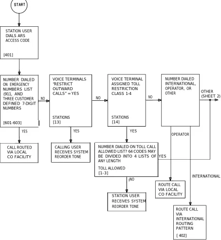
● Automatic Route Selection provides manager defined routing of calls over the telecommunications network based on preferred routes (normally the least expensive route available at the time the call is placed) with capacity for multiple common carriers and routing through tandem switch points. The user dials a standard DDD number and the system selects the call route.
● Station Message Detail Recording (SMDR) generates detailed call information on all incoming and outgoing calls and sends this information to an output device (PC or printer).
● C a l l A c c o u n t i n g S y s t e m s p r o v i d e m u l t i p l e t y p e s o f c u s t o m e r r e p o r t s o n communication costs and usage.
Ease of access to multiple types of network facilities (provided for minimum cost) is managed by:
● Automatic Route Selection (ARS) allows the customer to dial a standard DDD number. ARS selects the preferred route and does any number conversions required for the facilities selected.
● System 25’s Virtual Facility feature provides convenient and inexpensive access to OCCs. This feature provides access to OCC facilities over a user specified
physical
facility; dedicated OCC trunks are not needed. Local OCC access numbers and account codes are automatically added by System 25. System 25’s Virtual Facility feature is fully integrated with its ARS, Toll Restriction, and SMDR/CAS features.
● Last Number Dialed automatically saves the last number dialed and allows the user to retry the number without redialing. (Multiline voice terminals only)
● Repertory Dialing allows multiline voice terminal users to store a telephone number or account and associate that number with a button on their voice terminal. Pressing a Repertory Dial button is equivalent to dialing the stored number (one-touch dialing).
● System Speed Dialing allows all users to dial 90 selected numbers using three-digit codes. Users can also program up to seven Personal Speed Dial Numbers which are accessible only from their terminals. System Speed Dialing can be used by the system administrator to hide business account codes from users.
● Pooled Facility-Dial Access allows both multiline and single-line voice terminal users to access a common pool of trunks for outgoing calls by dialing a facility access code, or, on multiline voice terminals, by pressing a button . This grouping provides resource pooling which results in better service with a given number of trunks.
● Personal Lines provide dedicated outside lines for multiline voice terminal users. Personal lines are accessed via a dedicated feature button. Up to sixteen terminals may share a personal line.
● Third-Party Call Setup allows PCs to set up calls between a System 25 voice/data terminal and any other facility. A PC application program could use this capability to retrieve information from a database.
Last Number Dialed, Repertory Dialing and Speed Dialing are also applicable to dialing and managing internal calls. Personal lines provide both incoming and outgoing service.
Internal Call Movement
Typically, about 40 percent of PBX calls are internal calls, call transfers to another location, conference of multiple locations, temporarily suspended calls, page to locate the called party, etc. Rapid placement of internal calls and easy call movement from the answering station to a new station are supported in System 25 with numerous features.
To provide easy internal call setup, System 25 provides the following features.
● Automatic Intercom allows multiline voice terminal users to call each other by use of a dedicated line appearance. A private dedicated path ensures that a path is always available. This feature is frequently used in Boss/Secretary arrangements.
● The Dial Plan for System 25 is based on the concept that, whenever possible, calls should be placed to individuals rather than to pieces of equipment. To implement this concept, individuals are assigned Personal Dial Codes (PDCs) and are allowed to login those PDCs at other terminals. The system automatically routes the call to the home terminal or logged-into terminal. This significantly increases the probability of reaching the called party. In addition, the dial plan is built on a flexible numbering scheme which allows the number of dialed digits to match assigned PDCs (2/3/4 digit dial plans) and to be administered to match telephone company assigned Direct Inward Dialing numbers.
Efficient internal call termination is supported with the following features.
● Distinctive Ringing provides two types of ringing to allow users to distinguish between outside calls and inside calls,
● Hands-Free Answer on Intercom (HFAI) allows Speakerphone and HFAI terminals to auto-answer inside or attendant extended calls. With HFAI active, the set generates a tone burst over its speaker to alert the calling and called party of the call completion. Both parties may then converse; no action by the called party is required.
Frequently, the first termination point for a call is not its final destination. To support internal call movement, System 25 provides the following features.
● Transfer allows a user to transfer any call to another voice terminal. This feature supports transfer of calls from the answering position to another location for completion of a transaction. Examples are secretary to boss, office to lab, broker to specialist, etc.
● Conference allows up to five parties (maximum two outside), including the originator, to participate in a call. This feature supports add-on of additional parties to a call for joint consultation, crisis management, schedule coordination, etc.
● Hold allows a user to suspend a call. The Hold feature allows users to temporarily disconnect from one conversation and either place or answer another call. Music or information bulletins may be provided to the held party. Called parties frequently use the hold period to access computer data bases, search categories and/or consult with others via a second phone call.
● Call Park allows a user to place a call or conference on hold and then pick up the call from any voice terminal. The user can page another party to pick up the parked call or may move to another location and then re-access the call.
Data Communications
● Circuit switched data communications up to 19,200 bps (RS232 interface). This provides circuit switched connections from asynchronous data terminals, PCs, or host computers to host computers or network facilities. Users can be located and/or moved to any on-premises office equipped with the standard AT&T four-pair wiring plan. Thus an asynchronous terminal or PC can have access to multiple host c o m p u t e r s , r e m o t e d a t a b a s e s v i a a m o d e m p o o l , a n d a l o c a l a r e a n e t w o r k (STARLAN) via System 25’s STARLAN NETWORK gateway.
● P a c k e t s w i t c h e d d a t a c o n n e c t i o n s a t 1 m i l l i o n b p s o v e r A T & T ’ s S T A R L A N NETWORK local area network. This provides data transfer between client PCs and servers (PCs/host computers/printers, etc.) on the local area network (LAN). LAN users can be located and/or moved to any on-premises office equipped with standard AT&T four-pair wiring. The LAN allows PCs to share facilities (printers, disk systems, modem pools, etc.)
● System 25’s STARLAN NETWORK ACCESS software and STARLAN NETWORK gateway provide access to the STARLAN NETWORK for off-premises and occasional on-premises users. These users do not need to install a Network Access Unit (NAU) in their PCs to use the STARLAN NETWORK ACCESS software. The data transfer rate is limited to 9600 bps or, for off-premises users, by the modem.
LAN users can access hosts connected to System 25, or, if their System 25 is equipped with a modem pool, remote hosts. Finally, terminals and PCs connected to System 25 data ports can access host computers on the LAN.
Frequently a user needs to access a LAN data base at or from a remote location (home, motel, client office, branch, etc.). To support out-of-building access to computer data over network facilities or OPS lines, System 25 provides the following features.
● Modem pooling allows data terminals to communicate over analog facilities utilizing the standard dialing plan and provides full access to all network facilities, cost
control mechanisms, ARS, and incoming call management tools
(DID/attendant/DGC, etc.).
● Transfer to data allows a data call to be set up on a voice terminal and then be transferred to a data terminal or computer. This feature can also be used to enter an account code for the data call.
● The System 25 STARLAN NETWORK gateway allows the LAN environment to be extended to occasional users or remote locations. Off-premises users can access the LAN utilizing all the network features, cost control mechanisms, and incoming call management facilities of System 25. The data transfer rate is governed by the modem.
Setting up data communications with PCs, host computers, and/or remote access can be a source of confusion for occasional users. Special data features are provided by System 25 to assist the user in utilizing its rich set of data communications capabilities.
● The integrated voice-data dialing plan recognizes the different types of data endpoints (digital/ analog and remote/local) in a connection and automatically inserts the required data communication equipment. In addition, autobauding supports the alignment of equipment with the capacity to transmit at different data rates.
● Terminal Dialing provides the user with fast access to data communications via keyboard dialing at a terminal or PC.
● Command Mode provides a menu of data services supporting terminal dialing, and display and control of user data port options. A user friendly Change Options menu is provided for user administration of data options.
● Expert Mode is an enhancement that provides an alternative method of accessing Command Mode functions. Expert Mode eliminates the display of menus and allows multiple commands to be entered on a single line. Expert mode lends itself well to computer-driven scripts for call setup.
● Communication Access Manager (CAM) is an MS-DOS* software application that provides a phone manager for placing voice and data calls for the user and VT100† terminal emulation. CAM may be used on either STARLAN NETWORK client workstations or on PCs connected to System 25. CAM has a 200-entry directory with one-touch dialing for both voice and data calls and auto-login capability for data calls to host computers. CAM’s Remote Access feature provides password protected unattended access to PC files and electronic mail. File transfer is supported with the popular XMODEM protocol.
● STARLAN NETWORK ACCESS is an MS-DOS application that allows PCs not connected to the STARLAN NETWORK to call through the System 25 STARLAN NETWORK Interface and run STARLAN NETWORK client software to access file and printer servers on the STARLAN NETWORK. ACCESS uses a PC’s serial communications port to communicate with the STARLAN NETWORK Interface. ACCESS is compatible with NETBIOS, permitting execution of most applications written for the IBM‡ PC Network and IBM Token Ring Network.
Growth & Rearrangement
Historical data indicates that clients in the System 25 station range have a need for communications systems capable of significant growth and rearrangement. Clients need flexibility over the life of the system to easily add capacity, move stations, modify cost control options, etc. The architecture of System 25 was implemented with the objective of meeting this need.
● Advanced Administration (optional) is an easy-to-use, menu driven personal computer software package for configuring the rich set of system options.
● Uniform Wiring Plan (four-pair) allows a building to be prewired for the rich set of AT&T Small Business PBX service offerings. This modular wiring plan supports client reconfiguration of an office with variations in station type (Analog, MET, MERLIN, futures) and data configurations (LAN, asynchronous, synchronous). It supports simultaneous voice and data from standard four-pair modular jacks.
● System 25/75/85V2 Standard Architecture supports efficient growth with modular cabinets, universal carrier slots, non-blocking network and uniform wiring plan. (See
* Registered trademark of Microsoft Corp. † Trademark of Digital Equipment Corp.
Figures 1 and 2.) Every circuit slot in the system can be used for trunk cards or voice/data station cards. All these attributes allow the client to add future capability without breakage and re-engineering of existing equipment. Thus, the client is able to minimize initial investment while not restricting future growth.
Over time, the type of tools and facilities that a business utilizes changes. It is important that a PBX provide support for the full set of Telco network options over its installed life, even when only a subset is initially used. Trunks link two switching systems, such as System 25 and the local Central Office or System 25 and another PBX. System 25 supports five different telephone company trunk interfaces to provide desired connectivity at minimum expense. Thus the opportunity exists to select the best trunk types, depending on tariffs and customer needs.
● Loop Start (LS) trunks for public network access at minimum tariff. These trunks handle outgoing and incoming attendant calls, incoming DGC calls, outgoing pooled facility calls, and personal line calls.
● Ground Start (GS) trunks for public network access. These trunks handle the same type of calls as LS trunks. They provide protection against call reorigination without toll restriction, more reliable automatic route selection, virtual facilities, SMDR and CAS. Simultaneous incoming and outgoing call seizure of the same trunk under heavy traffic conditions is essentially eliminated with ground start trunks. GS t r u n k s s h o u l d u s u a l l y b e s e l e c t e d i n p r e f e r e n c e t o L S t r u n k s u n l e s s t a r i f f considerations are overriding. Note, however, that Centrex Service requires LS trunks.
● Direct Incoming Dial (DID) trunks for dialing a station directly from outside (attendant assistance not required). Outside dial access to stations, trunks (optional), and answering groups (Direct Group calling) is provided.
● Tie Trunks for linking PBXs with dedicated private circuits for high volume calling. Dial access to stations, other trunks, answering groups (Direct Group Calling) and an Electronic Tandem Network endpoint capability are provided.
● Off-Premises Stations (OPS) allow a single-line voice terminal to be located remotely and connected to System 25 via arrangements with the local Telco. This service is used to provide users at secondary sites (or their residences) many of the same features as an on-premises single-line station.
To enhance the usage and control of the above set of network facilities, System 25 provides the rich set of access features outlined in the Outgoing Business Communications Section. In addition, System 25 can support networking between systems by:
.
Serving as an endpoint on an electronic tandem network (ETN) using its tie trunks and flexible dialing plan..
Serving as an off-network or on-network access point with its dial access/transfer between tie-trunks and Telco trunks (LS/GS/DID). This allows usage of tie trunks to reach a distant System 25 and then connect through that System 25 to local Telco facilities to complete the call.Types of trunks which can be assigned in System 25 are:
● Central Office, which provide a link with the local telco for incoming and outgoing calls (LS/GS)
● Foreign Exchange (FX), which connect to a CO other than the local CO for high volume calling from a distant location
● Wide-Area Telecommunications Service (WATS), which connect to an Outward WATS office or a dial “800” Service Office
● Direct Inward Dial (DID), which provide incoming service from a CO to directly access a station or facility (STARLAN NETWORK interface, trunk group)
● Tie trunks, which provide a link with another private switching system.
To support efficient utilization of this rich set of network options, System 25 provides the functions outlined in the Outgoing and Incoming Business Communications sections.
Conclusions
USER CHANGEABLE OPTIONS (V2) . . . .
VIRTUAL FACILITIES (V2) . . . ● . . . . ● . . ● ●
LIST OF FIGURES
Figure 2-1. Direct Trunk Attendant Console . . . .
Figure 2-2. Direct Trunk Attendant Console Connections . . . .
Figure 2-3. Switched Loop Attendant Console . . . .
Figure 2-4. Console Buttons and Display . . . .
Figure 2-5. Switched Loop Attendant Console Connections . . . .
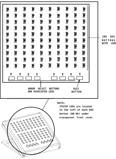
Figure 2-6. Model 23A1 Attendant Direct Extension Selector Console . . . . .
Figure 2-7. Attendant Direct Extension Selector Console Connections . . . . .
Figure 2-8. Automatic Route Selection Flow Chart . . . .
Figure 2-9. Automatic Route Selection Routing Pattern . . . .
Figure 2-10. Typical SMDR Call Detail Report . . . .
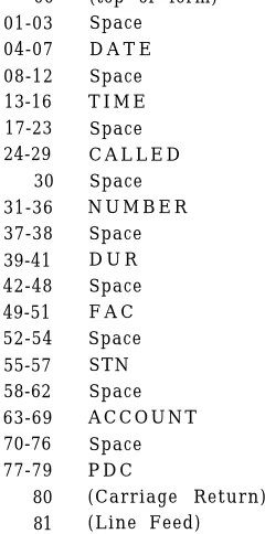
Figure 2-11. SMDR Call Record Format . . . .
Figure 2-12. SMDR Call Record Header Format . . . .
Figure 2-13. SMDR Output Equipment or Call Accounting System—On-Premises Direct Connections (Sharing Same AC Outlet) . . . .
Figure 2-14. SMDR Output Equipment or Call Accounting System—On-Premises Direct Connections (Greater Than 50 Feet From System
Cabinet) . . . .
Figure 2-15. SMDR Output Equipment–On-Premises Switched
Connections . . . .
Figure 2-16. SMDR Output Equipment—Off-Premises Direct Connections . . . .
Figure 2-17. SMDR Output Equipment–Off-Premises Switched
Connections . . . .
F i g u r e 2 - 1 8 . C o m m u n i c a t i o n s A c c e s s M a n a g e r A r c h i t e c t u r e . . . .
Figure 2-19. Asynchronous Data Unit Interface Signals . . . .
F i g u r e 2 - 2 0 . D i c t a t i o n S y s t e m C o n n e c t i o n s ( F C C R e g i s t e r e d ) . . . .
Figure 2-21. Digital Tape Unit . . . .
Figure 2-22. Digital Tape Unit–On-Premises Direct Connections (Sharing Same AC Outlet) . . . .
Figure 2-23. Delay Announcement Equipment Connections (FCC
Registered) . . . .
Figure 2-24. External Alert Connections . . . .
Figure 2-25. Supplemental Alert Adapter Connections . . . .
Figure 2-26. Figure 2-27. Figure 2-28. Figure 2-29. Figure 2-30. Figure 2-31. Figure 2-32. Figure 2-33. Figure 2-34. Figure 2-35. Figure 2-36. Figure 2-37. Figure 2-38. Figure 2-39. Figure 2-40. Figure 2-41. Figure 2-42. Figure 2-43. Figure 2-44. Figure 2-45. Figure 2-46. Figure 2-47. Figure 2-48. Figure 2-49. Figure 2-50. Figure 2-51.
500A/502A Headset Adapter . . . .
Typical Headset Adapter Connections For 7300H Series Multilane Voice Terminals (Except 34-Button Deluxe, BIS, or BIS with
Display) . . . .
Typical Headset Adapter Connections For 34-Button Deluxe, BIS, or BIS with Display Voice Terminals . . . .
Typical Headset Adapter Connections For 12-Button MET
Sets . . . .
Music-On-Hold Equipment Connections (FCC Registered) . . . . .
Music-On-Hold Equipment Connections (Non-Registered) . . . . .
Delay Announcement Equipment Connections (FCC
Registered) . . . .
Paging Equipment Connections Using CO Trunk Ports (FCC
Registered) . . . .
Paging Equipment Connection to TN763 Causing 278A
Adapter . . . .
10B Emergency Transfer Unit (ETU) . . . .
Emergency Transfer Unit Connections . . . .
Multiple ETU Arrangements . . . .
Speakerphone Adjuncts . . . .
Speakerphone Connections For 7300H Series Multilane Voice Terminals (Except 34-Button Deluxe) . . . .
Speakerphone Connections For 34-Button Deluxe Multiline Voice Terminals . . . .
Speakerphone Connections For 12-Button MET Sets . . . .
STARLAN NETWORK and System 25 Configuration . . . .
STARLAN NETWORK Connection to System 25 (With 2500 Single-Line Telephone) . . . .
STARLAN NETWORK Connection to System 25 (With ATL-Type Telephone) . . . .
Model 703 System Administration Terminal . . . .
SAT On-Premises Direct Connections (Sharing Same AC
Outlet) . . . .
SAT On-Premises Direct Connections (Greater Than 50 Feet From System Cabinet) . . . .
SAT On-Premises Switched Connections . . . .
SAT Off-Premises Direct Connections . . . .
SAT Off-Premises Switched Connections . . . .
Command Mode Menu Tree . . . .
TABLE 2-A. System Features . . . .
TABLE 2-B. Network Features . . . .
TABLE 2-C. Data Features.. . . .
TABLE 2-D. Station Features . . . .
TABLE 2-E. Attendant Features . . . .
TABLE 2-F. Partial List of Permissible Data Port (TN726) Options . . . .
TABLE 2-G. Typical Option Profiles for Different Types of Data Port
Endpoints . . . .
TABLE 2-H. Call Progress Messages for Data Terminal Dialing . . . .
TABLE 2-I. LED Indications . . . .
TABLE 2-J. User Changeable Options . . . .
2-2
2-3
2-3
2-4
2-5
2-97
2-98
2-114
2-157
SECTION 2—FEATURES AND SERVICES
This section describes the System Features, Network Features, Data Features, Station Features, and Attendant Features of AT&T System 25. It also covers certain services that support and implement the features; included in this category are the digital tape unit, the dial plan, system administration, and system maintenance. A general discussion of data topics is also provided.
The feature descriptions are arranged in alphabetical order, regardless of the feature group to which they belong. Information for each feature is presented under five headings: Description, Considerations, Interactions, Administration, and Hardware Requirements.
● Description
Defines the feature, describes what it does for the user, and how it is used.
● Considerations
Discusses the applications a n d b e n e f i t s o f t h e f e a t u r e , f o l l o w e d b y f e a t u r e parameters and factors to be considered when the feature is used.
● Interactions
Lists and briefly describes other features that can affect the feature being described. Interacting features are those that:
— Depend on each other—One of the features must be provided if the other one is.
— Cannot coexist–One of the features cannot be provided if the other one is. — Affect each other–The operation of one feature modifies, or is modified by,
the operation of the other.
— Enhance each other—The features, in combination, provide improved service to the user.
● Administration Requirements
S t a t e s w h e t h e r o r n o t a d m i n i s t r a t i o n i s r e q u i r e d a n d l i s t s i t e m s r e q u i r i n g administration.
● Hardware Requirements
List any additional hardware needed to use the feature.
Tabular listings of features by group (System, Network, Data, Station, or Attendant) immediately follow this introduction. Each type, standard, or optional of the feature, is also noted on these lists:
● S t a n d a r d f e a t u r e s — B u i l t i n t o e a c h s y s t e m ( a l w a y s p r o v i d e d b u t c a n r e q u i r e administration to make them operational)
● O p t i o n a l f e a t u r e s – S u c h a s M u s i c - O n - H o l d , r e q u i r e b o t h a d m i n i s t r a t i o n a n d additional hardware.
System Features
System features (Table 2-A) are those that affect the entire operation of the system. All system features are available with both Vl and V2.
TABLE 2-A. System Features
FEATURE NAME FEATURE
TYPE *
Call Accounting O
Dial Plan S
Dictation System Access O
Digital Tape Unit O
Direct Group Calling S
Direct Group Calling Delay Announcement O
End-to-End Signaling S
Extended Stations O
External Alerts O
Intercept Treatment With Reorder Tone S
Interdigit Timeouts S
Music-On-Hold O
Night Service (Directed and TAAS ) S / O †
Night Service Delay Announcements O
Out-Of-Building Stations O
Paging System Access O
Personal Dial Codes S
Pooled Facility-Dial Access S
Power Failure Transfer O
Remote Administration Interface O
Station Message Detail Recording O
System Administration O
System Maintenance S
Touch-Tone and Dial Pulse Service S
* Feature types: S= Standard; O= Optional (requires additional equipment).
Network Features
This group of features (Table 2-B) supports communications with the public network and with other locations in the private network of which System 25 can be a part.
TABLE 2-B. Network Features
FEATURE NAME FEATURE
TYPE *
Automatic Route Selection S
Direct Inward Dialing O
Off-Premises Stations O
Tandem Trunking (V2) O
Tie Trunks O
Trunk Groups S
Virtual Facilities (V2) S
Data Features
Data Features (Table 2-C) support the switched data services of the system. Data services provide switched connections between analog and digital data endpoints.
TABLE 2-C. Data Features
FEATURE NAME MULTILINE TERMINAL FEATURE BUTTON LABEL † TYPE *
Command Mode
Communications Access Manager (V2) Data Call Setup
Data Services Overview Data Terminal Dialing
Expert Mode (V2) Modem Pooling
AT&T STARLAN NETWORK Access (V2) Third-Party Call Setup (V2)
Transfer to Data
User Changeable Options (V2)
[DATA]
S O S
S S O
O S S S
* Feature types: S= Standard; O= Optional (requires additional equipment).
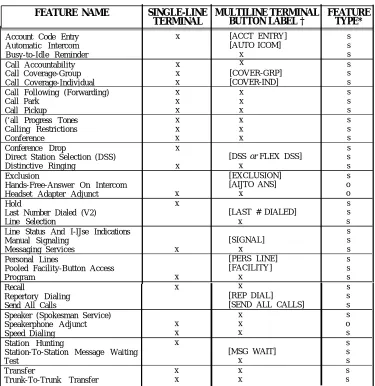
Station Features
The many Station Features (Table 2-D) available allow individual user needs to be met. As these needs change, assigned features can also be changed. Station Features provide many important services that help save time and make calling more convenient.
TABLE 2-D. Station Features
FEATURE NAME SINGLE-LINE MULTILINE TERMINAL FEATURE TERMINAL BUTTON LABEL † TYPE*
Account Code Entry x [ACCT ENTRY] s
Automatic Intercom [AUTO ICOM] s
Busy-to-Idle Reminder x s
Call Accountability x x s
Call Coverage-Group x [COVER-GRP] s
Call Coverage-Individual x [COVER-IND] s
Call Following (Forwarding) x x s
Call Park x x s
Call Pickup x x s
(’all Progress Tones x
Calling Restrictions
x s
x x s
Conference x x s
Conference Drop x s
Direct Station Selection (DSS) [DSS or FLEX DSS] s
Distinctive Ringing x x s
Exclusion [EXCLUSION] s
Hands-Free-Answer On Intercom [AIJTO ANS] o
Headset Adapter Adjunct x x o
Hold x s
Last Number Dialed (V2) [LAST # DIALED] s
Line Selection x
Line Status And I-IJse Indications
s s
Manual Signaling [SIGNAL] s
Messaging Services x x s
Personal Lines [PERS LINE] s
Pooled Facility-Button Access [FACILITY] s
Program x x s
Recall x x s
Repertory Dialing [REP DIAL] s
Send All Calls [SEND ALL CALLS] s
Speaker (Spokesman Service) x s
Speakerphone Adjunct x x o
Speed Dialing x x s
Station Hunting x s
Station-To-Station Message Waiting [MSG WAIT] s
Test x s
Transfer x x s
Trunk-To-Trunk Transfer x x s
* Feature types: S= Standard; O= Optional (requires additional equipment).
Attendant Features
Attendant Features (Table 2-E) are available to the attendant using the Direct Trunk Attendant Console (DTAC) or the Switched Loop Attendant Console (SLAC) (V2 only) and (optionally) a Direct Extension Selector Console. In addition, most multiline voice terminal station features are available to the attendant.
TABLE 2-E. Attendant Features
FEATURE NAME CONSOLE BUTTON FEATURE LABEL † TYPE *
Attendant Call Extending [START] S
Attendant Camp-On S
Attendant Cancel [CANCEL] S
Attendant Console, Direct Trunk O
Attendant Console, Switched Loop (V2) O
Attendant Display (V2; SLAC only) S
Attendant Direct Extension Selection O
Attendant Forced Release V2; SLAC only) [FORCED RELEASE] S
Attendant Join (V2; SLAC only) [JOIN] S
Attendant Message Waiting (DTAC) [ATT MSG] S
Attendant Message Waiting (SLAC) [ATTENDANT
MESSAGE WAITING] S
Attendant Position Busy [POS BIJSY] S
Attendant Release [RELEASE] S
Attendant Return-Coverage-on-Busy [RTN-BUSY]‡ S
Attendant Return-Coverage-on-Don’t-Answer [RTN-DA]‡ S Attendant Source/Destination (V2; SLAC only) [SOURCE] S
[DEST] S
Attendant Splitting One-Way Automatic S
Attendant System Alarm Indication [ALARM] S
Message Center-Like Operation (V2; SLAC only) S
Night Service [NIGHT] S
*
†
Feature types: S=Standard; O=Optional.
Bracketed words are the labels for button-activated features; these labels are also used in feature descriptions where applicable.
This button is assigned on the DTAC only.
ACCOUNT CODE ENTRY
Description
Allows voice terminal users to associate an account code with incoming and outgoing calls. This is accomplished by entering the account code at the voice terminal before hanging up. The account code is appended to the SMDR call record and can be used later for accounting or billing purposes.
To association account code with a call, the user, after completing a call but before hanging up, must:
● Single-Line Voice Terminal User:
— Flash the switchhook and dial *O; then dial the account code directly or dial a System or Personal Speed Dial Number that contains the account code. If the number is entered incorrectly, redial *0 and the correct number before hanging up.
● Multilane Voice Terminal User:
— Press Account Code Entry (ACCT ENTRY) button and then dial the account code directly or dial a System or Personal Speed Dial Number that contains the account code. A Repertory Dial (REP DIAL) button can also be used to enter an account code. If the number is dialed incorrectly, press ACCT ENTRY again (before hanging up) and dial the correct number.
● When the correct number of account code digits have been entered (o r# is entered to signal end-of-dialing), Confirmation Tone followed by Dial Tone is returned to the user and the account code is appended to the SMDR call record.
Account Code Entry is optional.
Considerations
Account Code Entry provides an easy method of allocating the costs of specific calls (and associated staff time) to the correct project, department or user. The account code is appended to the SMDR call record and sent to the SMDR output channel.
Account Codes can include up to 15 digits.
The validity of the entered account code is not checked by the system.
If the user is active on a call, invoking the feature will drop the call.
Incorrectly dialed codes (prior to last digit entry) can be corrected by dialing *0 or pressing ACCT ENTRY and reentering the code. Partial account codes entered by going on-hook before completing entry are recorded and cannot be corrected.
If, before all digits have been entered, (1) the user goes on-hook, (2) a button other than ACCT ENTRY is pressed, or (3) 30 seconds have elapsed since the feature was invoked, the SMDR call record will show the digits dialed up to that point.
Interactions
● C o n f e r e n c e : If more than one user attempts to enter an account code on a
Conference Call, the first to enter a code will prevail.
● Repertory Dialing: An Account Code can be stored on a REP DIAL button. Press
REP DIAL after ACCT ENTRY has been pressed.
● Speed Dialing: An Account code can be stored in System or Personal Speed Dial
Number.
● Transfer: A user can transfer a call to another user, then, before hanging up, enter
an account code. Subsequent account code entries for the same call will be ignored, even though confirmation tone has been returned.
Administration Requirements
System:
● Maximum number of Account Code digits (0-15)--Default = 15. Voice Terminal: (Station Port)
● Multiline terminals–Account Code Entry Button is required. ● Single-line terminals–none.
Hardware Requirements
ATTENDANT CALL EXTENDING
Description
Allows the attendant to put a call in a special hold condition, call another station, then connect the two calls together. The attendant can withdraw from the connection and separate the call from the console or remain connected to the other parties. Attendant Call Extending is a feature used at either a Direct Trunk Attendant Console (DTAC) or a Switched Loop Attendant Console (SLAC).
Note: In general, the attendant
should not
use the TRANSFER button, which invokes the standard multiline voice terminal Transfer feature, to extend calls. If Transfer is used, busy or unanswered calls cannot return to the attendant console for further handling.The attendant, after placing or answering a call, can use Step 1 or 2 to extend this call to an inside extension or Step 1 to extend it to an outside number:
1. Press START to place the incoming call on hold via the Attendant Splitting One-Way Automatic feature. After receiving Dial Tone, the attendant then dials the requested inside or outside number.
o r
2. Press the Selector Console Group Select and Direct Extension Selection (DXS) buttons associated with the requested inside station. This operation is equivalent to pressing START and dialing the extension.
If ringing tone is heard, the attendant presses RELEASE (Manual Release) to connect the caller to the ringing line and separate the call from the console. As an alternative, the attendant can press any facility button such as System Access, Automatic Intercom, or an outside line (Attendant Automatic Release) to complete the call extending procedure.
The attendant has the option of staying connected to the ringing line to announce the call before connecting the two parties. The attendant can then release or (SLAC only) join the other parties in a 3-way connection by using the Attendant Join feature.
If busy tone is heard and Attendant Camp-On (see associated feature description) is not desired, the attendant presses CANCEL and is reconnected to the calling party.
If busy tone is heard on a call to an inside station and Attendant Camp-On is desired, the attendant presses RELEASE or any facility button. The called party hears a tone burst, and the call waits at the called voice terminal. When a busy single-line station goes on-hook, or a busy multiline station System Access button becomes idle, the call automatically begins ringing at the station. Only one Camped-On call is permitted per voice terminal.
Considerations
Attendant Call Extending allows the attendant to utilize the additional attendant related features such as Attendant Splitting One-Way (automatically places incoming canon hold), Release, Cancel, Return-On-Don’t-Answer, Return-On-Busy, Forced Release (SLAC), Join (SLAC), and Source/Destination (SLAC).
Interactions
Refer to the other Attendant Feature descriptions for information on related features (Table 2-E).
Administration Requirements
System:
● Number of seconds before a Camped-On call returns to the Attendant Console (1-120 seconds), or No Attendant Camp-On (0) - Default = 30 seconds
● Number of rings before unanswered call returns to the Attendant Console (131) -Default = 5.
Hardware Requirements
ATTENDANT CAMP-ON
Description
Allows the attendant to extend a trunk call to a busy voice terminal and leave it waiting or “camped on” there. After hearing busy tone, the attendant presses RELEASE to camp-on this call at the busy terminal. When this is done, a burst of tone is heard in the handset of the called terminal and the caller is placed on hold (hearing music-on-hold if available). When a System Access button at a multiline set becomes idle or a single-line terminal hangs up, the camped-on call is connected automatically and ringing begins. Only one call can be camped-on to a voice terminal. This feature is referred to as a “Waiting Call” in the U s e r
Guides for the System 25 voice terminals.
Considerations
A camped-on call can be answered by a busy single-line user without losing the current call by momentarily pressing the switchhook (which places the current call on hold) and then dialing *9. Multiline terminal users cannot do this. However, if they have a System Access-Originate Only button, they can place both calls on hold, go off-hook on that button and dial *9 to pick up the camped-on call.
If the camped-on call is not answered within a specified time, the call will be returned to the Attendant Console in one of the following ways:
● Switched Loop Attendant Console: The call returns to the common queue, where
it remains until the console can receive it at a LOOP button.
● Direct Trunk Attendant Console: The call returns to the Return-On-Busy
(RTN-BUSY) button. If that button is busy, the call remains camped-on at the called terminal until the RTN-BUSY button of the console becomes idle.
Interactions
● Call Coverage/Direct Group Calling (DGC): If the called party is a member of
a hunt or Call Coverage group (or, for V1 systems only, a DGC group) and all members of the group, or all receivers of the Coverage group are busy, the call will not hunt or receive coverage. Once camped-on, calls will no longer hunt or receive coverage even if the hunted-to station or group member becomes idle.
● Direct Group Calling: For V2, the attendant can camp-on more than one call per
DGC group. For VI, the attendant can camp-on only one call per DGC group; if the attendant attempts to camp-on a second call, it is immediately returned on the RTN-BUSY button on the DTAC. Voice terminals in the group do not receive a burst of tone when a call is camped on.
● Direct Inward Dialing (DID): DID calls can be covered by the attendant and
then given Camp-On treatment. They do not automatically receive Call Waiting.
Administration Requirements
System:
● Number of seconds before a camped-on call returns to the Attendant Console (1-120 seconds) or No Attendant Camp-On allowed (0) - Default = 30 seconds.
Hardware Requirements
ATTENDANT CANCEL
Description
Allows the attendant to terminate an attempt to extend any incoming call if the called station does not answer, or if the station answers but declines to accept the call. Before pressing RELEASE, the attendant presses CANCEL and is automatically reconnected to the calling party.
Pressing CANCEL when the Start facility is not active will be ignored.
Considerations
Attendant Cancel allows the attendant to terminate a call transfer attempt and return to the incoming held party via a one-button operation. This enhances the attendant’s ability to handle calls quickly and efficiently.
Interactions
None
Administration Requirements
None Required
Hardware Requirements
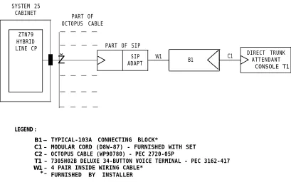
ATTENDANT CONSOLE, DIRECT TRUNK
Description
In System 25, the Attendant Console is used to answer incoming trunk calls that are not directed to specific user stations, to answer calls from inside users, to extend calls to inside stations and outside numbers, and to assist system users in placing outgoing calls and setting up conferences. The attendant can also manage and monitor some areas of system operation. System 25 R1Vl supports only the Direct Trunk Attendant Console (DTAC). The R1V2 supports either the DTAC or the Switched Loop Attendant Console (SLAC), that is described in the next subsection of this manual.
The DTAC (Figure 2-1) is a 34-Button Deluxe Voice Terminal administered with special features, buttons, and capabilities to serve as an attendant position. In addition to the attendant features, all standard multiline terminal features are also available. (Refer to the Hardware Description section of this manual for a complete identification of the external controls, indicators, and components of the basic voice terminal. )
DIRECT TRUNK ATTENDANT OPTIONAL SELECTOR
CONSOLE CONSOLE
Figure 2-1. Direct Trunk Attendant Console
The DTAC is always equipped with the following feature buttons that provide unique attendant console functions. Each button has a green status LED that indicates when the feature is activated.
● Start [START] Initiates the call extending process by placing a caller on hold and
providing internal dial tone to the attendant
● Cancel [CANCEL]: Terminates the “Start” operation and reconnects the attendant
to the calling party.
● Release [RELEASE]: Releases the attendant from an active call and completes the
call extending process.
● Return-On-Busy [RTN-BUSY]: Camped-on calls are returned to the console on
● Return-On-Don’t-Answer [RTN-DA]: Extended calls not answered are returned to the console on this button if not answered within a specified interval.
● Attendant Message Waiting [ATT MSG]: Used by the attendant to remotely
control Message LEDs on voice terminals.
● Alarm [ALARM]: The associated status LED flashes when a system trouble has
been detected; the LED can be changed from flashing to steadily lit by pressing the button.
Two other attendant-only features are assigned to console feature buttons if required, Position Busy [POS BUSY] and Night Service [NIGHT]. In a dual attendant console system, Position Busy removes an Attendant Console from service. Only one of two consoles can be in the “Position Busy” mode at a time. When Night Service is activated, attendant-seeking calls can ring a night bell, can be directed to assigned voice terminals, or can be sent to a night service announcement.
Considerations
Direct trunk operation means that trunks are terminated on individual buttons, called Personal Line buttons, where outside calls are answered and originated. The console can have several incoming calls ringing simultaneously.
Each console can also have an optional Attendant Direct Extension Selector Console to enhance internal calling. The Selector Console is described in the “Attendant Direct Extension Selection” subsection.
Dual Console Operation:
A System 25 can be equipped with up to two DTACs that operate simultaneously when both are in service. If the system has two attendant consoles, one is called the first attendant console (primary attendant console in VI); the other is called the second attendant console (secondary attendant console in Vi). The calls in the following list will be routed to the first attendant console.
● Dial “0” calls
● DID calls to unassigned numbers (when administered to route to the attendant)
● Calls to Floating Personal Data Codes (FPDCs) not logged in (when administered to route to the attendant)
If the first attendant has activated the Position Busy feature or is busy on both System Access buttons, these calls will be routed to the second console. If that console is also busy on both System Access buttons, busy tone is provided to the calling party.
For V2 only: See the “Call Coverage—Individual” feature description for information about
simulating
additional System Access buttons for handling more incoming calls.System users and DID callers can reach a particular attendant by dialing that personal Data Codes (PDC).
Position Busy:
terminations on the rightmost two columns of buttons of the inactive console. Ringers disabled on an inactive console will be enabled on the active console for those trunks with dual appearances (appearances on both consoles). All other features on all buttons, including those on the associated Attendant Direct Extension Selector Console will continue to function normally even though the console is inactive.
Interactions
A DTAC cannot operate in the same system with a SLAC.
Refer to the Attendant Feature descriptions for information on other related features as listed in Table 2-E.
Administration Requirements
System:
● Assign Primary and Secondary Attendant Positions (Vi)
● Display attendant position number (first or second) (V2)
● Assign number of rings before unanswered calls return to the Attendant Positional-31) -Default = 5 rings
● Send DID calls to unassigned numbers to the Attendant Position (Yes, No) -Default = Yes
● Send calls to Floating Personal Dial Codes that are not logged-in to the Attendant Position (Yes, No) -Default = Yes
● Assign number of seconds before an unanswered Camped-On Call returns to the Attendant Console (1-120 seconds), or No Attendant Camp-On (0) - Default = 30 seconds.
Attendant Console: (Station Port)
● Voice terminal type = 309 (V2) ● Special Programmable Buttons:
— Night Service
— Position Busy
— Attendant Message Waiting (assigned by default).
Note: The following buttons are predefined on the Attendant Console and are not administrable:
– Alarm
— Return-On-Don’t-Answer — Return-On-Busy
— Start
— Release
● Trunk terminations–The following is required for each trunk terminated on the c o n s o l e ( a d m i n i s t e r e d a s P e r s o n a l L i n e a p p e a r a n c e s ; D I D t r u n k s c a n n o t b e terminated on a DTAC):
Trunk Number
— Make this the Principal Station (owner) of the trunk (Yes, No)
— Enable Ring (Yes, No).
Hardware Requirements
Each console requires a port on a ZTN79 ATL Line circuit pack.
Figure 2-2 provides a connection diagram for the DTAC.
SYSTEM 25 CABINET
PART OF
ZTN79 HYBRID LINE CP
OCTOPUS CABLE
— — — —
— — — —
Ž
— — — —
— — — —
— — — —
LEGEND :
B1 — C1 – C2 – T1 – W1 – * –
PART OF SIP
SIP W1 C1 DIRECT TRUNK
ADAPT B1 ATTENDANTCONSOLE
T1
TYPICAL-103A CONNECTING BLOCK*
MODULAR CORD (D8W-87) - FURNISHED WITH SET OCTOPUS CABLE (WP90780) - PEC 2720-05P
7305H02B DELUXE 34-BUTTON VOICE TERMINAL - PEC 3162-417 4 PAIR INSIDE WIRING CABLE*
FURNISHED BY INSTALLER
RANGE: WITHIN 2000 FEET OF SYSTEM CABINET (LOCAL POWER REQUIRED >1000 FEET)
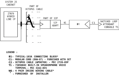
ATTENDANT CONSOLE, SWITCHED LOOP (V2)
Description
In System 25, the Attendant Console is used to answer incoming trunk calls that are specified to ring at an attendant position, to answer calls from inside users, to extend calls to inside stations and outside numbers, to assist system users in placing outgoing calls, and to set up conferences. The attendant can also manage and monitor some areas of system operation. System 25 R1V1 supports only the Direct Trunk Attendant Console (DTAC), which is described in the preceding subsection of this manual. The R1V2 supports either the DTAC or the Switched Loop Attendant Console (SLAC), but not both in the same system.
The SLAC (Figure 2-3) is a 34-Button Built-In Speakerphone (BIS) Voice Terminal with a 16-character display module. I t i s a d m i n i s t e r e d w i t h s p e c i a l b u t t o n s , f e a t u r e s , a n d capabilities to serve as an attendant console. In addition to the attendant features, most s t a n d a r d m u l t i l i n e t e r m i n a l f e a t u r e s a r e a l s o a v a i l a b l e . ( R e f e r t o t h e “ H a r d w a r e Description” section of this manual for a complete identification of all the external controls, indicators, and components of the basic voice terminal. )
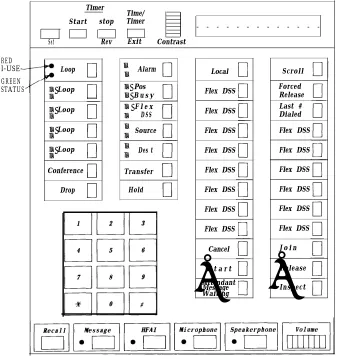
SWITCHED LOOP ATTENDANT CONSOLE
OPTIONAL SELECTOR CONSOLE
Figure 2-3. Switched Loop Attendant Console
Associated with the SLAC are message center-like capability and display support. The message center feature provides for efficient handling of calls that should be sent to message takers. These calls are directed to a message center console position through administration of call type translations. Display service allows identifiers (names) to be assigned to extension numbers and trunks. The system then displays the appropriate information to the attendant when calls are processed at the console.
Fixed Buttons (Figure 2-4)
I n a d d i t i o n t o t h e L O O P b u t t o n s a n d s t a n d a r d m u l t i l i n e t e r m i n a l b u t t o n s ( H O L D , TRANSFER, etc.), the console is equipped with the following feature buttons that provide unique ● ● ● ● ● ● ● ● ● ● ● ● ● ●
attendant functions. Unless noted, the buttons have green status LEDs.
Start [START]: Initiates the call extending process by placing a caller on hold (on
the Source button) and providing internal dial tone to the attendant. No LED.
Cancel [CANCEL]: Terminates the “Start” operation and reconnects the attendant
to the calling party (on the Source button). No LED.
Release [RELEASE]: Releases the attendant from an active call and completes the
call extending process. No LED.
Source [SOURCE]: Reconnects the attendant to the calling party after a call has
been initiated to the called party but before the two parties have been connected together.
D e s t i n a t i o n [ D E S T ] : Connects the attendant to the called party again after the
attendant has operated the Source button to speak to the calling party.
Join [JOIN]: Joins together (in a 3-way connection) the attendant and the other
parties in an extended call. No LED.
Forced Release [FORCED RELEASE]: Drops all active parties from a call. No
LED.
Last Number Dialed [LAST # DIALED]: Redials the last number dialed. No
LED.
Position Busy [POS BUSY]: Temporarily removes the attendant position from
service.
Attendant Message Waiting [ATTENDANT MESSAGE WAITING]: Used by
the attendant to remotely control Message LEDs on voice terminals.
Alarm [ALARM]: The associated status LED flashes when a system trouble has
been detected; the LED can be changed from flashing to steadily lit by pressing the button.
I n s p e c t [ I N S P E C T ] : Puts the display into a mode for inspecting the status or
stored information of certain buttons.
Scroll [SCROLL]: Causes display to present additional call information, when
available. No LED.
Local [LOCAL]: Allows display to be used for clock and calendar functions. No
LED.
The buttons not assigned to normal voice terminal functions or to attendant functions are defaulted to the Flex DSS feature. One of these programmable buttons can be assigned to Night Service, if the feature is required, and any of the others to multiline voice terminal features.
Programmable Feature Buttons (Figure 2-4)
The features in the following list can be assigned to the programmable feature buttons. On the SLAC these buttons are not equipped with lamps for indicating feature status conditions.
● Manual Signaling
● Transfer to Data ● Account Code Entry
● Auto Intercom
● Auto A n s w e r
● Direct Facility Access
● Direct Station Selection (DSS)
● Flex DSS
● Repertory Dialing.
The last two features can be programmed with dialable numbers by the attendant. When a call is placed using a Flex DSS button or a Repertory Dial button, one of the five switched loops is automatically selected for routing the call to the switch.
Display (Figure 2-4)
The SLAC contains an alphanumeric call information display. This module is built into the top of the console. It contains a 16-character 5x7 dot matrix liquid crystal display, timer controls, and a thumbwheel Contrast adjustment. Timer functions are available only when the attendant presses the Local button. The Time/Timer Exit button allows the user to select ordinary clock/calendar display or a timer. In the Time mode, Set, Fwd, and Rev are used to set the clock. In Timer mode, Start and Stop are used to time events.
The primary purpose of the console display is to provide the attendant with descriptive information about incoming and outgoing calls. This information includes extension numbers and associated names, trunk identifiers, reasons for call return and redirection, and number of calls waiting in the queue for service. Refer to the “Attendant Display” feature description, for a detailed discussion of call information displays.
Considerations
An R1V2 system configuration can support either one or two SLACs or one or two DTACs, but not a combination of a SLAC and a DTAC.
The Switched Loop Console derives its name from the ability of the system to hold incoming attendant-bound calls in a queue and switch them on voice loops to an available console. Calls are directed to a console in a preadministered, prioritized sequence. The SLAC differs from the DTAC in the following basic respects:
● It receives calls one at a time, regardless of the number of incoming calls to the system (at the DTAC, many incoming calls can be ringing simultaneously).
● It displays pertinent information about incoming and outgoing calls.
● It can serve as an attendant console, a message center, or a combination of both.