August 1991
MERLIN LEGEND
Communications System
MERLIN LEGEND™ Communications System
System Reference
555-610-110
Ignore all references to the small processor module. The MERLIN LEGEND™ Communications System offers onIy one procssor module. This processor module is referred to as a large processor module in this document.
Ignore references to the "small" processor module on the following pages:
Page 1-21, System Capacities.
Page 2-105, Direct-Line Console. Table 2-4, Maximum Number of System Operator Positions.
Page 2-112, Directory, Considerations. third bullet from top and third bullet from bottom of page.
Page 2-131, Direct Station Selector, Considerations, second bullet
Page 2-251, Paging, Considerations, third bullet
Page 2-294, Queued Call Console, Table 2-13, Maximum Number of System Operator Positions and fifth bullet
Page 2-337, Speed Dial, first paragraph.
Page 2-339, Speed Dial, first, third, and eighth bullets.
Page 5-4, Processor Module, first paragraph.
Page 6-1, Capacities, first paragraph.
Pages 6-2-6-5, Table 6-1, Hardware and Software Capacities
Page 6-7, Backboard Dimensions.
Appendix A - Page A-1
Ordering Codes Table The following Price Element Code (PECs) are not valid: Small (Analog) - 6141-CUA
Small (Digital) - 6141-CUD Small (Digital) - 6141-24D Appendix A - Page A-2
Ordering Codes Table: The following Price Element Code (PEC) is not valid: Upgrade from Small to Large - 6140-USLA
Notice
Every effort was made to ensure that the information in this book was completed and accurate at the time of printing. However, Information is subject to change.
Federal Communications Commissions (FCC) Information
For important FCC interference, registration, and repair information, see "Customer Support Information" in this book.
Trademarks
Accunet is a registered trademark of AT&T. Dimension is a registerd trademark of AT&T. Horizon is a registered trademark of AT&T. Magic on Hold is a registed trademark of AT&T. Megacom is a registed trademark of AT&T. MERLIN is a registed trademark of AT&T. MERLIN LEGEND is a trademark of AT&T. MERLIN MAIL is a trademark of AT&T.
MLX-10, MLX-10D, MLX-20L, and MLX-28D aretrademarks of AT&T. MultiQuest is a registered trademark of AT&T.
SYSTIMAX is a trademark of AT&T.
MS-DOS is a registered trademark of Microsoft Corporation. PagePac is a registered trademark of DRACON, a Harris Corporation. Starset is a registred trademark of Plantonics Corporation. Supra and StarMate are trademarks of Palntonic Corporation.
Zonemate trademark of DRACON, a division of Harris Corporation.
Support Telephone Number
Customer Support Information
xv■ Support Telephone Number xv
■ FCC/DOC Information xv
■ Security xix
■ Warranty xix
About This Book
xxi■ Related Documentation xxi
■ How to Order Books xxii
■ Additional Ordering Information xxiii
■ Product Safety Labels xxiii
■ How to Comment on This Book xxiii
1
System Overview
1-1■ Components 1-2
■ Capabilities 1-7
■ System Programming 1-22
2
Features
2-1■ ■ ■ ■ ■ ■ ■ ■ ■ ■ ■ ■ ■ ■ ■ Introduction Feature Tables Account Code Entry Alarm
Allowed Lists Auto Answer All Auto Answer Intercom Auto Dial
Automatic Line Selection Automatic Maintenance Busy Automatic Route Selection
■ Camp-On
■ Conference
■ Coverage
■ Direct-Line Console
■ Directory
■ Direct Station Selector
■ Disallowed Lists
■ Display
■ DO Not Disturb
■ Extension Status
■ Forced Account Code Entry
■ Forward and Follow Me
■ Group Calling
■ Headset Options
■ Hold
■ Inside Dial Tone
■ Inspect
■ Labeling
■ Last Number Dial
■ Line Request
■ Messaging
■ Microphone Disable
■ Multi-Function Module
■ Music-on-Hold
■ Night Service
■ Paging
■ Park
■ Personal Lines
■ Pickup
■ Pools
■ Power Failure Transfer
■ Privacy
■ Programming
■ Queued Call Console
■ Recall
■ Reminder Service
■ Remote Access
■ Ringing/idle Line Preference
■ Ringing Options
■ Saved Number Dial
■ Signaling
■ Speed Dial
■ ■ ■ ■ ■ ■ ■
Station Message Detail Recording 2-343
System Access 2-349
System Numbering 2-360
Toll Type 2-366
Touch-Tone or Rotary Signaling 2-366
Transfer 2-371
Voice Announce to Busy 2-382
3
System Applications
3-1Voice Messaging Systems Call Accounting System Call Accounting Terminal Call Management System Integrated Solution II MERLIN Attendant
MERLIN MAIL Voice Messaging System
System Programming and Maintenance (MS-DOS)
3-3 3-6 3-10 3-13 3-17 3-25 3-28 3-34
4
Functional Description
4-1■ ■ ■ ■ ■ ■
Control Unit Operation 4-1
Modes of Operation 4-7
Lines/Trunks 4-23
DS1 Facilities 4-27
System Alarms 4-33
Power Failure Transfer 4-37
5
Hardware
5-1■ Control Unit 5-2
■ Telephones and Consoles 5-10
■ Adapters 5-19
■ Adjuncts 5-30
■ Accessories 5-48
6
System Capacities and Requirements
6-1■ Capacities 6-1
■ Environmental Requirements 6-6
■ Power and Grounding 6-8
A
Parts Information
A-1B
General Telephone Programming Instructions
5-1C
General Feature Use Instructions
C-1D
Programming Special Character
D-1E
System Programming Console Overlay
E-1F
System Programming Reports
F-1G
The System Programming Menu Hierarchy
G-1H
Unit Load Calculation Work Sheet
H-1AB
Abbreviations Glossary
AB-1GL
Glossary
GL-1IN
Index
IN-11
System Overview
1-11-1 System Components 1-4
1-2 Individual Use Data Station Configurations 1-11
1-3 Modem Pools Assigned to Data Hunt Groups 1-13
1-4 DHGs Connected to local Host Computer and LAN Workstation 1-15
1-5 Nontandem Tie-Trunk Network 1-18
1-6 Tandem Tie-Trunk Network 1-19
1-7 Intertandem Tie-Trunk Network 1-20
2
Features
2-12-1 2-2 2-3 2 4 2-5 2-6 2-7 2-8 2-9 2-10 2-11 2-12 2-13 2-14 2-15 2-16 2-17 2-18 2-19 2-20 2-21
ARS Process 2-44
Primary and Secondary Individual Coverage Ringing Patterns 2-86
Group Coverage Only or All Individual Coverage Receivers Not Available 2-92 Individual (Primary and Secondary), and Group Coverage
Ringing Patterns 2-93
Direct Station Selectors 2-118
DSS Extension Assignment Sequence 2-119
2-Line Display Home Screen 2-140
7-Line Display Home Screen 2-141
2-Line Display Menu Screen 2-141
7-Line Display Menu Screen 2-141
2-Line Display Inspect Screen for Programmed Button 2-142
7-Line Display Inspect Screen for Programmed Button 2-142
2-Line Display inspect Screen for Programmed Button 2-208
7-Line Display Inspect Screen for Programmed Button 2-208
MLX-20L Telephone 2-282
System Programming and Maintenance (SPM) Display 2-283
QCC Fixed Features Assigned to Line Buttons 2-287
Sample SMDR Report in ISDN Format 2-343
Two-Digit Numbering Plan 2-361
Three-Digit Numbering Plan 2-362
Set Up Space Numbering Plan 2-363
3
System Applications
3-1 CAS Connection Less Than 50 Feet
3-2 CAS Connection 50 Feet or More
3-3 CAT Connection
3-4 CMS Connection to Control Unit
3-5 IS II Connection Less Than 50 Feet
3-6 IS II Connection 50 Feet or More
3-7 SPM+S II Connection 50 Feet or More
3-8 Connection of MERLIN MAIL Voice Messaging System
3-9 Connection of SPM Under 50 Feet
3-10 Connection of SPM 50 Feet or More
3-1 3-6 3-9 3-12 3-16 3-22 3-23 3-24 3-33 3-36 3-37
4
Functional Description
4-1 Functional Units
4-2 Lines Labeled for Key System Telephones
4-3 Lines labeled for Modified Key System Telephones
4-4 Hybrid/PBX Mode of Operation
4-5 Behind Switch Mode
4-6 Behind Switch Mode with Direct Outside Lines
4-7 Labeled Line Buttons for Behind Switch Telephones
4-8 Trouble Alarm Connections
4-9 Power Failure Alarm Connections
4-10 Power Failure DID Busy-Out Connections
4-11 Ground-Start Button
4-1 4-2 4-8 4-10 4-13 4-17 4-18 4-19 4-34 4-35 4-36 4-37
5
Hardware
5-1 5-2 5-3 5-4 5-5 5-6 5-7 5-8 5-9 5-10 5-11 5-12 5-13 5-14 5-15 5-16 5 1 7 5-18 5-19 5-20 5-21 5-22 5-23 5-24 5-25 5-26 5-27 5-28 5-29Control Unit Housing Carriers
Power Supply Module Processor Module
Line/Trunk and Station Modules MLX-28D Telephone
MLX-20L Telephone MLX-10D Telephone MLX-10D Telephone
551 T1 L1 Channel Service Unit Connections ESF T1 Channel Service Unit Connections Multi-Function Module
GPA Connections
ISDN 7500B Data Module Front Panel ISDN 7500B Data Module Back Panel SAA Connections
Single-Zone Paging with PagePac 20
Single-Zone Paging with Customer-Supplied Amplifier Single-Zone Paging with Paging Access Module
Single-Zone Paging with Background Music and MOH Multizone Paging with Background Music, MOH, and Talk-Back Music Coupler
Direct Station Selector MLX Telephone Headsets
Analog Multiline Telephone Headset Analog IROB Connection
MLX IROB Connection Surge Protectors Ground-Start Button 5-1 5-2 5 3 5-4 5-5 5-7 5-11 5-12 5-13 5-14 5-19 5-20 5-21 5-23 5-24 5-25 5-29 5-31 5-37 5-39 5-40 5-40 5-50 5-51 5-52 5-54 5-32 5-33 5-34 5-35
6
System Capacities and Requirements
6-16-1 Surge Protection Units 6-9
E
System Programming Console Overlay
E-1 Console Overlay
E-2 SPM Screen
E-3 System Programming Console Screen
E-1 E-1 E-2 E-2
1
System Overview
1-11-1 Configurations of Data Stations 1-10
2
Features
2-12-1 2-2 2-3 2-4 2-5 2-6 2-7 2-8 2-9 2-10 2-11 2-12 2-13 2-14 2-15 System Features
Telephone and System Operator Features Group Coverage Call Delivery Rules
Maximum Number of System Operator Positions Results of Pressing DSS Button While Active on a Call
LED Meanings for Normal Call-Handling Operation without Message Status Active
LED Meanings for Supervisor Operation without Message Status Active LED Meanings for Hotel Extension Status Operation without Message Status Active
Message Status Operation-LED Meanings Feature Screen Options
Feature Interactions with sample Displays Factory-Set Posted Messages and Their Codes Maximum Number of System Operator Positions Distinctive Ringing Patterns
Number of TTRs Required
2-3 2-6 2-90 2-105 2-121 2-125 2-127 2-128 2-129 2-143 2-144 2-211 2-294 2-324 2-368
3
System Applications
3-13-1 Applications: System Capacity and Modes of Operation 3-2
3-2 TTRs Required by VMS 3-3
3-3 Voice Channels Required 3-18
3-4 Number of Attendants 3-25
3-5 MERLIN MAIL Ports Required 3-29
4
Functional Description
4-14-1 Tie-Trunk Compatibility 4-6
4-2 Summary of Modes of Operation 4-22
4-3 Line Compensation Settings 4-31
5
Hardware
5-15-1 Line/Trunk and Station Modules 5-8
5-2 Analog Multiline Telephones 5-15
5-3 Single-Line Telephones 5-16
5-4 Telephones and Adjuncts Not Supported 5-17
5-5 Adjunct Summary 5-43
6
System Capacities and Requirements
6-16-1 Hardware and Software Capacities 6-2
6-2 Control Unit Requirements 6-6
F
System Programming Reports
F-1F-1 F-2 F-3 F-4 F-5 F-6 F-7 F-8 F-9 F-10 F-1 1 F-12 F-13 F-14 F-15 F-16 F-17 F-18 F-19 F-20 F-21 System Information Dial Plan Label Information Trunk Information DS1 information PRI Information Remote Access Operator Information Allowed Lists
Access to Allowed Lists Disallowed Lists
IMPORTANT SAFETY INSTRUCTIONS
When installing telephone equipment, basic safety precautions should always be followed to reduce the risk of fire, eliectric Shock, and injury to persons, including:
■ ■ ■ ■ ■ ■ ■ ■ ■ ■ ■ ■ ■ ■ ■ ■ ■
Read and understand all instructions.
Follow all warnings and instructions marked on or packed with the product. Never install telephone wiring during a lightning storm.
Never install telephone jacks in a wet location unless the jack is specifically designed for wet locations.
Never touch uninsulated telephone wires or terminals unless the telephone wiring has been disconnected at the network interface.
Use caution when installing or modifying telephone lines.
Use only AT&T manufactured MERLIN LEGEND™ circuit modules, carrier assemblies, and power units in the MERLIN LEGEND (511A) control unit.
Use Only AT&T-recommended/approved MERLIN LEGEND accessories.
if equipment connected to the analog station modules (008/408/408 GS/LS) or to the MLX telephone module (008 MLX) is to be used for in-range out-of-building (IROB) applications, IROB protectors are required.
Do not install this product near water, for example, in a wet basement location. Do not overload wall outlets as this can result in the risk of fire or electric shock.
The MERLIN LEGEND is equipped with a three-wire grounding-type plug, a plug having a third (grounding) pin. This plug wlli fit only into a grounding-type power outlet. This is a safety feature. If you are unable to insert the plug into the outlet, contact an electrician to replace the obsolete outlet. Do not defeat the safety purpose of the grounding plug.
The MERLIN LEGEND system requires a supplementary ground.
Do not attach the power supply cord to building surfaces. Do not allow anything to rest on the power cord. Do not locate this product where the cord wll be abused by persons walking on it.
Slots and openings in the module housings are provided for ventilation. To protect this equipment from overheating, do not block these openings.
Never push objects of any kind into this product through module openings or expansion slots, as they may touch dangerous voltage points or short-out parts, which could result in a risk of fire or electric shock. Never spill liquid of any kind on this product.
Unplug this product from the wall outlet before cleaning. Do not use liquid or aerosol cleaners on this product. Use a damp cloth for cleaning.
Support Telephone Number
AT&T provides a toll-free customer Helpline (1-800-628-2888) 24 hours a day (U.S.A. only). Call the Helpline, or your authorized dealer, if you need assistance when installing, programming, or using your system.
Federal Communications Commission (FCC)
Electromagnetic Interference Information
This equipment has been tested and found to comply with the limits for a Class A digital device, pursuant to Part 15 of the FCC Rules. These limits are designed to provide reasonable protection against harmful interference when the equipment is operated in a commercial environment. This equipment generates, uses, and can radiate radio frequency energy and, if not installed and used in accordance with the instruction manual, may cause harmful interference to radio communications. Operation of this equipment in a residential area is likely to cause harmful interference, in which case the user will be required to correct the interference at his own expense.
Canadian Department of Communications (DOC)
Interference Information
This digital apparatus does not exceed the Class A limits for radio noise emissions set out in the radio interference regulations of the Canadian Department of Communications.
Le présent appareil numérique n’émet pas de bruits radioélectriques dépassant Ies limites applicables aux appareils numériques de la classe A prescribes dens Ie Règlement sur Ie brouillage radioélectrique édicté par le ministère des Communications du Canada.
FCC Notification and Repair Information
This equipment is registered with the FCC in accordance with Part 68 of its rules. In compliance with those rules, you are advised of the following:
■ Means of Connection. Connection of this equipment to the telephone network shall be through a standard network interface
jack: USOC RJ11C, RJ14C, RJ21X. Connection to E&M tie trunks requires a USOC RJ2GX. Connection to off-premises stations requires a USOC RJ11C or RJ14C. Connection to 1.544 Mbs digital facilities must be through a USOC RJ48C or RJ48X. Connection to DID requires a RJ11C, RJ14C or RJ21X. These USOCS must be ordered from your telephone company.
This equipment may not be used with party lines or coin telephone lines.
■ Notification to the Telephone Companies. Before connecting this equipment, you or your equipment supplier must notify
your local telephone company’s business office of the following:
■ The telephone number(s) you will be using with this equipment.
■ The appropriate registration number and ringer equivalence number (REN), whlch can be found on the back or bottom of
the control unit, are as follows:
If this equipment is to be used as a Key System, report the following number AS593M-72914-KF-E, and if the system provides both manual and automatic selection of incoming/outgoing access to the network, report AS593M-72682-MF-E. The ringer equivalence number for both systems is 1.5A.
■ For tie line connection, provide the telephone company the facility interface code (FIC) of TL31M and the service order
code (SOC) 9.0F.
■ For connection to off-premises stations, report the FIC 0L13C and SOC 9.0F.
■ If this equipment is to be connected to digital service (1.544 Mbs), the FIC is 04DU9-B for D4 training format or 04DU9-C
for extended framing format, and SOC 6.0P.
■ If this equipment is to be connected to DID facilities, the FIC is 02RV2-T, and the SOC is 9.0F.
■ The quantities and USOC numbers of the jacks required.
■ For each jack, provide the sequence in which lines are to be connected: the type lines, the FIC, and REN by position
when applicable.
You must also notify your local telephone company if and when this equipment is permanently disconnected from the line(s). The REN is used to determine the quantity of devices which maybe connected to the telephone line. Excessive REN’s on the telephone line may result in the devices not ringing in response to an incoming call. In most, but not all, areas the sum of the REN’s should not exceed five (5.0). To be certain of the number of devices that may be connected to the line, as determined by the total REIN’s, contact the telephone oornpany to determine the maximum REN for the calling area.
Installation and Operational Procedures
The manuals for your system contain information about installation and operational procedures.
■
■
■
■
equipment can be made only by the maufacturers, their authorized agents, or by others who may be authorized by the FCC. Repair Instructions. If you experience trouble because your equipment is malfunctioning, the FCC requires that the equipment not be used and that it be disconnected from the network until the problem has been corrected. Repairs to this
In the event repairs are needed on this equipment please contact the National Service Assistance Center (NSAC) at 1-800 626-2666, or your authorized AT&T dealer.
Rights of the Local Telephone Company. If this equipment causes harm to the telephone network, the local telephone company may discontinue your service temporarily. If possible, they will notify you in advance. But if adadvance notice is not practical, you will be notified as soon as possible. You will also be informed of your right to file a complaint with the FCC. Your local telephone oompany may make changes in its facilities, equipment operations, or procedures that affect the proper functioning of this equipment. If they do, you will be notified in advance to give you an opportunity to maintain uninterrupted telephone service.
Hearing Aid Compatibility. The custom telephone sets for this system are compatible with inductively coupled hearing aids as prescribed by the FCC.
Automatic Dialers. WHEN PROGRAMMING EMERGENCY NUMBERS AND/OR MAKING TEST CALLS TO EMERGENCY NUMBERS:
■ Remain on the line and briefly explain to the dispatcher the reason for the call.
■ Peform such activities in the off-peak hours, such as ealy morning or late evening.
DOC Notification and Repair Information
NOTICE: The Canadian Department of Communications (DOC) label identities certified equipment. This certification means that the equipment meets certain telecommunications network protective, operational, and safety requirements. The DOC does not guarantee the equipment will operate to the user’s satisfaction.
Before installing this equipment, users should ensure that it is permissible to connectit to the facilities of the local
telecommunications company. The equipment , must also be installed using an acceptable method of connection. In some cases,
the company’s inside wiring for single-line individual service may be extended by means of a certified connector assembly (telephone extension cord). The customer should be aware that compliance with the above conditions may not prevent degradation of service in some situations.
Repairs to certified equipment should be made by an authorized Canadian maintenance facility designated by the supplier. Any repairs or alterations made by the user to this equipment, or any equipment malfunctions, may give the telecommunications company cause to request the user to disconnect the equipment.
Users should ensure for their own protection that the electrical ground connections of the power utility, telephone lines, and internal metallic water pipe system, if present, are connected. This precaution may be particularly important in rural areas.
CAUTION: Users should not attempt to make such connections themselves, but should contact the appropriate electric inspection authority or electrician, as appropriate.
To prevent overloading, the Load Number (LN) assigned to each terminal device denotes the percentage of the total load to be connected to a telephone loop used by the device. The termination on a loop may consist of any combination of devices subject only to the requirement that the total of the Load Numbers of all the devices does not exceed 100.
DOC Certification No. 230 4095A CSA Certification No. LR 56260 Load No. 6
Renseignements sur la notification du ministère des Communications du Canada et la réparation
AVIS: L'étiquette du ministère des Communications du Canada identifie Ie matériel homologué. Cette étiquette certifie que Ie matériel est conform à certaines normes de protection, d’exploitation et de sécurité des réseaux de télécommunications. Le ministère n’assure toutefois pas qua Ie matériel fonctionnera à la satisfaction de l’utilisateur.
Avant d'installer ce matériel, I’utilisateur doit s’assurer qu’il est permis de le raccorder aux installations de I’entreprise locale de télécommunication. Le rmatériel doit également être installé en suivant une méthode acceptée de raccordernent. Dans certains cas, les fils intérieurs de l'nterprise utilises pour un service individuel à ligne unique peuvent être prolongés au moyen d'un dspositif homologué de raccordement (cordon prolongateur téléphonique interne). L’abonné ne doit pas oublier qu’il est possible qua la conformité aux conditions énoncées ci-dessus n’empëchent pas la dégradation du service dens certaines
situations. Actuellement, les entreprises de télécommunication ne permettent pas que l'on raccorde leur matériel à des jacks
d’abonné, sauf dans les cas précis prévus par Ies tarifs particuliers de ces entreprises.
Les réparations de matériel homologué doivent être effectuées par un centre d'entretien canadien autorisé dèsigné par Ie fournisseur. La compagnie de télécommunications peut demander à I’utilisateur de débrancher un appareil à la suite de réparations ou de modifications effectuées par I’utilisateur ou à cause de mauvais fonctionnement.
Pour sa propre protection, I’utilisateur doit s’assurer que tous Ies fils de mise à la terre de la source d'énergie électrique, des lignes téléphoniques et des canalisations d'eau métalliques, s'il y en a, sont raccordés ensemble. Cette précaution est particulièbrement irnportante dans les régions rurales.
AVERTISSEMENT: L’utilisateur ne doit pas tenter de faire ces raccorderments lui-même; il doit avoir recours à un service d’inspection des installations électriques, ou à un électricien, salon le cas.
L’indice de charge (IC) assigné à chaque dipositif terminal indique, pour éviter toute surchage, le pourcentage de la charge totale qui peut être raccordée à un circuit téléphonique bouclé uilisé par ce dipositif. La terminaison du circuit bouclé peut être constituée de n’irnporte quelle combinaison de dispositifs, pourvu qua la somme des indices de charge de I’ensemble des dispositifs ne dépasse pas 100.
No d'homologation 230 4095A Node certification CSA: LR 56260 L’indice de charge: 6
AT&T
MERLIN LEGEND ™
This device complies with Part 15 of the FCC Rules. Operation is subject to the following two conditions: (1) this device may not cause harmful interference, and (2) this device must accept any interference received, including interference that may cause undesired operation. Complies with Part 68, FCC Rules, FCC Reg. No. AS593M-72682-MF-E. Ringer Equivalence 1.5A. When equipped with the "KF" option (key only), FCC Reg. No. AS593M-72914-KF-E, Ringer Equivalence 1.5A.
Model 511A Control Unit
LISTE
D
538
E
TELEPHONE
EQUIPMENT
®
LR 56260
MADE IN USA
Use only AT&T manufactured MERLIN LEGEND circuit modules, carrier assemblies, and power units, as specified in the Installation manual, in this product. There are no user serviceable parts inside. Contact your authorized agent for service and repair. This digital apparatus does not exceed the Class A limits for radio noise emissions set out in the radio interference regulations of the Canadian Department of Communications. Le Present appareil numerique n'emet pas de bruits radioelectriques depassant les limites applicables aux appareils numeriques de la classe A prescrites dans le Reglement sur le brouillage radioelectrique edicte par le ministere des Communications du Canada.
WARNING:
If equipment is used for
Security of Your System-Preventing Toll Fraud
As a customer of a new telephone system, you should be aware that there exists an increasing problem of telephone toll fraud. Telephone toll fraud can occur in many forms, despite the numerous efforts of telephone companies and telephone equipment manufacturers to control it. Some individuals use electronic devices to prevent or falsify records of these calls. Others charge calls to someone else’s number by illegally using lost or stolen calling cards, billing innocent parties, clipping on to someone els's line, and breaking into someone else’s telephone equipment physically or electronically. In certain instances, unauthorized individuals make connections to the telephone network through the use of remote access features.
The Remote Access feature of your system, if you choose to utilize it. permits off-premises callers to access the system from a remote telephone by using an 800 number or a 7- or 10- digit telephone number. The system returns an acknowledgement signaling the user to key in his or her authorization code, which is selected and administered by the system manager. After the authorization code is accepted, the system returns dial tone to the user. If you do not program specific egress restrictions, the user will be able to place any call normally dialed from a telephone associated with the system. Such an off-premises network call is originated at, and will be billed from, the system location.
The Remote Access feature, as designed, helps the customer, through proper administration, to minimize the ability of unauthorized persons to gain access to the network. Most commonly, phone numbers and codes are compromised when overheard in a public location, through theft of a wallet or purse containing access information, or through carelessness (writing codes on a piece of paper and improperly discarding it). Additionally, hackers may use a computer to “dial" an access code and then publish the information to other hackers. Enormous charges can be run up quickly. It is the customer’s responsibility to take the appropriate steps to property implement the features, evaluate and administer the various restriction levels, protect access codes, and distribute access codes only to individuals who have been fully advised of the sensitive nature of the access information.
Common carriers are required by law to collect their tariffed charges. While these charges are fraudulent charges made by persons with criminal intent, applicable tariffs state that the customer of record is responsible for payment of all long-distance or other network charges. AT&T cannot be responsible for such charges and will not make any allowance or give any credit for charges that result from unathorized access.
To minimized the risk of unauthorized access to your communications system:
■ ■ ■ ■ ■ ■ ■ ■ ■
Use a nonpublished Remote Access number.
Assign authorization codes randomly to users on a "need-to-have” basis, keeping a log of ALL authorized users and assigning one code to one person.
Use random sequence authorization codes, which are less likely to be easily broken. Deactivate all unassigned codes promptly.
Ensure that Remote Access users are aware of their responsibility to keep the telephone number and any authorization codes secure.
When possible, restrict the off-network capability of off-premises callers, via use of Call Restrictions and Disallowed List capabilities.
When possible, block out-of-hours calling.
Frequently monitor system call detail reports for quicker detection of any unauthorized or abnormal calling patterns. Limit Remote Call Forward to persons on a “need-to-have" basis.
Limited Warranty and Limitation of Liability
Limited Warranty
AT&T warrants to you, the customer, that your MERLIN LEGEND Communications System will be in good working order on the date AT&T or its authorized reseller delivers or installs the system, whichever is later ("Warranty Date”). If you notify AT&T or its authorized reseller within one year of the Warranty Date that your system is not in good working order, AT&T will without charge to you repair or replace, at its option, the system components that are not in good working order. Repair or replacement parts may be new or refurbished and will be provided on an exchange basis. If AT&T determines that your system cannot be repaired or replaced, AT&T will remove the system and, at your option, refund the purchase price of your system, or apply the purchase price towards the purchase of another AT&T system.
If you purchased your system directly from AT&T, AT&T will perform warranty repair in accordance with the terms and conditions of the specific type of AT&T maintenance coverage you selected. A written explanation of AT&T's types of maintenance
coverage may be obtained from AT&T by calling 1-800-247-7000. If you purchased your system from an AT&T authorized reseller, contact your reseller for the details of the maintenance plan applicable to your system.
lThis AT&T limited warranty covers damage to the system caused by power surges; including power surges due to lightning.
The following will not be deemed to impair the good working order of the system. and AT&Twill not be responsible under this limited warranty for damages resulting from
■ failure to follow AT&T's installation, operation, or maintenance instructions
■ unathorized system modification, movement or alteration
■ unauthorized use of common carrier communication services accessed through the system
■ abuse, misuse, or negligent acts or omissions of the customer and persons under the customer’s control
■ acts of third parties and acts of God
AT&T'S OBLIGATION TO REPAIR, REPLACE OR REFUND AS SET FORTH ABOVE IS YOUR EXCLUSIVE REMEDY.
EXCEPT AS SPECIFICALLY SET FORTH ABOVVE AT&T, ITS AFFILIATES, SUPPLIERS, AND AUTHORIZED RESELLERS MAKE NO WARRANTIES, EXPRESS OR IMPLIED, AND SPECIFICALLY DISCLAIM ANY WARRANTIES OF MERCHANTABILIlY OR FITNESS FOR A PARTICULAR PURPOSE.
LIMITATION OF LIABILITY
EXCEPT FOR PERSONAL INJURY, DIRECT DAMAGES TO TANGIBLE PERSONAL PROPERTY PROXIMATELY CAUSED BY AT&T, AND LIABILITY OTHERWfSE EXPRESSLY ASSUMED IN A WRITTEN AGREEMENT SIGNED BY AT&T, THE LIABILTY OF AT&T, ITS AFFILIATES, SUPPLIERS AND AUTHORIZED RESELLERS FOR ANY CLAlMS, LOSSES, DAMAGES OR EXPENSES FROM ANY CAUSE WHATSOEVER (INCLUDING ACTS OR OMISSIONS OF THIRD PARTIES) REGARDLESS OF THE FORM OF ACTION, WHETHER IN CONTRACT, TORT OR OTHERWISE, SHALL NOT EXCEED AN AMOUNT EQUAL TO THE LESSER OF THE DIRECT DAMAGES PROVEN OR THE PURCHASE PRICE OF THE SYSTEM. IN NO EVENT SHALL AT&T OR ITS
AFFILIATES, SUPPLIERS OR AUTHORIZED RESELLERS BE LIABLE FOR lNCIDENTAL RELIANCE CONSEQUENTLY, OR ANY OTHER INDIRECT LOSS OR DAMAGE (INCLUDING LOST PROFITS OR REVENUES) INCURRED IN CONNECTION WITH THE SYSTEM. THIS LIMITATION OF LIABILlTY SHALL SURVIVE FAILURE OF THE EXCLUSIVE REMEDY SET FORTH IN THE LIMITED WARRANTY ABOVE.
This book provides general technical information about the communications system. It is intended for persons who plan, implement, coordinate, and manage the system (called system managers).
Related Documentation
The following books are available to help you set up, use, and maintain the communications system:
■ reference
■ setup and modification
■ telephone user support
■ operator guides
■ miscellaneous
How
to Order Books
The books needed for operating the communications system were supplied with the system. You can order additional copies of these and other books listed below from the AT&T Customer Information Center:
■ Within the continental United States, call 1-800-432-6600.
■ In Canada, call 1-800-255-1242.
MERLIN LEGEND
Book Title
Order Number
System Reference
System Reference 555-610-110
System Setup and Modification
Key System Planning 555-610-112
Key System Planning Forms 555-610-116
PBX System Planning 555-610-113
PBX System Planning Forms 555-610-117
Data Guide 555-610-114
Data Planning Forms 555-610-118
System Progamming 555-610-111
Telephone User Support
Analog Multiline Telephones User’s Guide 555-610-120 MLX-10D,™ MLX-28D,™ and MLX-20L™ Digital/ISDN
Display Telephones User’s Guide 555-610-122 MLX-10™ Digital/ISDN Non-Display Telephone
User's Guide 555-610-123
MLX-10™ and MLX-10D™ User Cards 555-610-124 MLX28D™ and MLX-20L™ User Cards 555-610-125 Single-Line Telephones User’s Guide 555-610-121
Operator Guides
Analog Direct-Line Consoles Operator’s Guide 555-610-131 Digital-lSDN Direct-Line Consoles Operator’s Guide 555-610-132 Digital-ISDN Queued Call Console Operator’s Guide 555-610-133
Miscellaneous
Calling Group Supervisor’s Guide 555-610-130
Additional Ordering Information
For information on ordering replacement parts, accessories, and other equipment that is compatible with the system, see Appendix A in System Reference.
Product Safety Labels
Throughout this book, hazardous situations are indicated by an exclamation point inside a triangle, along with the word caution or warning.
WARNING:
Warning indicates the presence of a hazard that could cause death or severe personal injury if the hazard is not avoided.
CAUTION:
Caution indicates the presence of a hazard that will or can cause minor personal injury or property damage if the hazard is not avoided.
How to Comment on This Book
We welcome your feedback on this book. Please use the feedback form that follows. If the form is missing, send your comments to A. Sherwood, AT&T, 99 Jefferson Road, Rm. #2A25, Parsippany, NJ 07054.
The MERLIN LEGEND™ Communications System is an advanced digital switching system that integrates voice and data communications features. Voice features combine traditional telephone features, such as Transfer and Hold, with advanced features, such as Group Coverage and Park. Data features enable the transmission of voice and data over the same system wiring.
This chapter describes the following aspects of the system.
■ Components-the equipment that makes up the system
■ Capabilities-the voice, data, and call-handling capabilities of the system
■ Programming-the methods and equipment used in system programming
Components
The system consists of required and optional components:
■ required components
■ control unit
■ telephones
■ optional components
■ adjuncts
■ adapters
■ applications
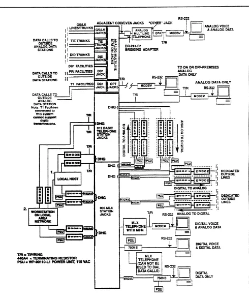
Figure 1-1 on page 4 shows the components of the system. The numbered paragraphs following the figure correspond to the numbered items in the figure.
Control Unit
The control unit consists of the basic carrier and any expansion carriers. These include the processor module, power supply modules, and line/trunk and station modules. (See Chapter 5, "Hardware," for a detailed description.)
Telephones
The telephones that can be used with the system are the digital/ISDN (MLX) telephones, the analog multiline telephones (including cordless telephones), and the single-line telephones. (See Chapter 5, “Hardware," for a detailed description.)
Adjuncts
Adjuncts are pieces of equipment that connect directly to the control unit or to a telephone through an adapter (see “Adapters" below). Answering machines, credit card verification terminals, and alerts are examples of adjuncts. For more information on adjuncts, see Chapter 5, "Hardware.”
Adapters
Adapters enable the connection of equipment or, in the case of a channel service unit (CSU), of Digital Signal 1 (DS1) facilities to the control unit. Some adapters oonnect directly to the control unit (system adapters) while others connect to telephones (telephone adapters):
■ System Adapters
■ ESF T1 CSU
■ 551 T1 L1 CSU
■ Universal Paging Access Module (UPAM)
■ Telephone Adapters
■
■
Multi-Function Module (MFM) for MLX telephones
General Purpose Adapter (GPA) for analog multiline telephones
■ ISDN 7500B Data Module for connecting digital data equipment either
directly to the control unit or to an MLX telephone (for simultaneous voice and data transmission)
■
■
modem for connecting digital equipment (such as a personal computer) to a tip/ring (T/R) interface
Supplemental Alert Adapter (SAA) for connecting an alert (such as a horn or strobe) to an analog multiline telephone
Applications
Applications for the MERLIN LEGEND Communications System consist of software and/or hardware that add functions to the system:
■ Call Accounting System (CAS)
■ Call Accounting Terminal (CAT)
■ Call Management System (CMS)
■ Integrated Solution II (IS II)
■ AUDIX Voice Power — IS II
■ Integrated Voice Power Automated Attendant
■ Call Accounting System — IS II
■ System Programming and Maintenance — IS II
■ MERLIN MAIL™ Voice Messaging System
■ MERLIN® Attendant
■ System Programming and Maintenance (SPM)
See Chapter 3, “System Applications,” for descriptions.
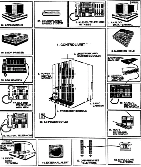
Figure 1-1 System Components
Control Unit. The backbone of the system, consisting of the basic and 1. 2. 3. 4. 5. 6. 7. 8. 9. 10. 11. 12.
expansion carriers, power supply module, processor module, and line/trunk and Station modules. The control unit connects telephone company
lines/trunks with stations such as telephones and adjuncts,
Line/Trunk and Station Modules. The components that connect telephone company lines/trunks and terrninal equipment such as telephones, external alerts, and fax machines via jacks to the control unit.
Carrier (Basic). The component attached to the backboard used to hold the modules needed for system operation. The basic carrier houses the
processor module, power supply module, and up to five line/trunk and station modules. Each expansion carrier houses its own power supply module and up to six additional line/trunk and/or station modules. One or two expansion carriers can be added.
Processor Module. A miniature computer that controls most of the system’s features, and supplies the system’s diagnostics. The processor module provides two jacks, one for Station Message Detail Recording (SMDR) and the other for system programming and maintenance via a personal computer (PC).
Power Supply Module. The component that supplies DC power for the modules and telephones (one power supply unit is needed per carrier). If the system’s power requirements exceed the capacity of the power supply module, an auxiliary power supply unit can be added.
Direct Station Selector (DSS). A console that adds 50 buttons for one-touch extension dialing to the MLX-20L™ or MLX-28D™ telephone and speeds call handling.
Analog Data Station. A data terminal such as a PC, printer, or optical reader that connects, via a modem (for transmitting and receiving analog signals), to a 012 basic telephone module or a 008 OPT module. A data terminal can also be connected to an MLX telephone using a Multi-Function Module (MFM) or to an analog multiline telephone using a General Purpose Adapter (GPA).
Magic on Hold®. Optional equipment that connects to the system through a ground-start/loop-start (GS/LS) jack programmed for Music-on-Hold. (A customer-provided music source can be connected instead of Magic on Hold.)
General Purpose Adapter (GPA). An adapter used to connect a variety of tip/ring (T/R) adjuncts to an analog multiline telephone (shown here with an answering machine).
Analog Multiline Telephone. A 34-button telephone with built-in
speakerphone that connects to the system via an analog station jack. Other analog multiline telephones compatible with the system include the 22- and 34-button with built-in speakerphone and a one-line, 16-character display, and the 10- and 22-button with built-in speakerphone, without display.
MLC5 Cordless Telephone. A cordless multiline telephone that connects to the control unit via an analog station jack.
lndustry-Standard Single-Line Telephone. A touch-tone or rotaty industry-standard telephone connected to the system via 012 basic telephone module or a 008 OPT module.
13. Off-Premises Telephone (OPT). A single-line, touch-tone or rotary, industry-standard telephone located in a different building from the control unit.
14. External Alert. Alerting devices such as bells, chimes, and strobe lights that connect to a jack on a 012 basic telephone module or a 008 OPT module, or to an MFM or Supplemental Alert Adapter (SAA)
15. Digital Data Station. A data terminal such as a PC, printer, or optical reader that connects via an ISDN 7500B Data Module to a 008 MLX module and that can also include an MLX telephone.
16. MLX-20L™ Telephone. A digital/lSDN (MLX) telephone with 20 line buttons and a display with seven lines of 24 characters each. The MLX-20L
telephone can be used as a system programming console. Other MLX telephones:
■ MLX-10™/MLX-10D™Telephone. A 10-button MLX telephone with or
tele without a two-line, 24-character display.
■ MLX-28D™ Telephone. An MLX telephone with 28 line buttons and a
two-line, 24-character display.
17. Multi-Function Module (MFM). A circuit board mounted inside an MLX telephone that provides a jack to connect optional equipment such as answering machines, fax machines, external alerts, and modems to the telephone.
18. Fax. Industry-standard fax machines connected to the control unit via a jack on a 012 basic telephone module or a 008 OPT module, an MFM, or a GPA.
19. SMDR Printer. A printer for SMDR call records, connected via an RS-232 jack on the processor module.
20. Applications. Software and hardware for the MERLIN LEGEND
Communications System that can be connected to the control unit to provide more functions.
21. Loudspeaker Paging. A single-zone or multizone system such as PagePac* with Zonemate† 9 or 39 that connects via an administered jack on a GS/LS module.
22. AC Power Outlet. A dedicated 115-VAC wall outlet (not controlled by an on/off switch) that supplies power to the control unit.
* PagePac is a registered trademark of Dracon, a division of Harris Corporation.
Zonemate is a trademark of Dracon, a division of Harris Corporation.
Capabilities
The following system capabilities are described in this chapter:
■
■
■
■
■
Modes of Operation
modes of operation
data
network
system capacities
DS1 capabilities
Key Mode
Hybrid/PBX
Mode
The system is for customers in the 10 to 140-station range. It can be configured to operate in one of three modes:
■ Key
■ Hybrid/PBX
■ Behind Switch
See "Modes of Operation" in Chapter 4 for a functional description of the modes.
In the Key mode, every line appears on a separate button on each multiline telephone. The line buttons allow users to see activity on other telephones, join conversations, make calls, and receive calls. Separate intercom buttons are used to make and receive internal calls.
A Key system automatically assigns the first eight outside lines to all telephones. Through system programming this arrangement can be customized to allow more outside line appearances on telephones. Also, lines or groups of lines can be assigned to selected groups of telephones or to individual telephones.
The Hybrid/PBX mode handles a large volume of calls and users and provides the most flexibility of the three modes. The outside trunks can be grouped in pools for shared use. in addition, outside trunks can be assigned to line buttons on multiline telephones for users who need a personal line.
Users access inside lines and outside trunks via System Access buttons. To make an outside call, the user enters a dial-out code, usually a 9, and the system automatically selects an available trunk. The Automatic Route Selection (ARS) feature determines which trunk should be used for each type of outgoing call.
Incoming calls can be handled by either a direct-line console (DLC) or a queued call console (QCC), or by a combination of both.
Behind Switch Mode
The Behind Switch mode is used when the System is connected to a PBX or Centrex system. This other system (called the host) provides the interface to outside lines and some features.A Behind Switch system assigns only one line (called a prime line) to each telephone. Outside lines to telephones or groups of telephones are assigned through system programming.
In the Behind Switch mode, users have access to the special features of both their system and the host system.
Lines/Trunks by Mode
Different types of lines/trunks are used for the different functions of each mode.A Key or Behind Switch system can use
■
■
■
■
Ioop-start lines
tie trunks
a DS1 facility programmed for either T1 or ISDN-PRI operation
a ground-start line only when registered under the MF FCC classification
A Hybrid/PBX system can use
■ Ioop-start trunks
■ ground-start trunks
■ tie trunks
■ Direct Inward Dialing (DID) trunks
■ a DS1 facility programmed for either T1 or ISDN-PRI operation
Data Capabilities
For more information on data. . The system can provide data connections between two digital data modules communication hardware requirements,
feature descriptions, planning, (ISDN 7500B Data Modules), between two analog modems, or between an programming, and using data analog modem and a digital data module. The system can also provide access communications equipment, see the to an in-house host computer or to a data station on a network.
Data Guide.
Data facilities include
■
■
■
■
digital data endpoints - RS-232 and V.35 interfaces via ISDN 7500B Data Modules
analog data endpoints - T/R modem interfaces
local host computer and workstation on local area network (LAN) access
DS1 facility interface
Data Stations
A data station is any location that includes a data terminal (such as a personal computer, printer, or fax machine) connected to the system via a modem or a data module, such as an ISDN 7500B Data Moduie. The modem or data module transmits information to and from the data terminal and, in many cases, provides dialing and answering capability. During data communications, a modem or data module functions similarly to the way a telephone functions during voice communications-it makes, maintains, and ends a call.The two types of data stations that can be connected to the system are analog and digital. Both types can include a telephone for users who require
simultaneous voice and data capability.
■ Analog Data Station uses a modem to convert the digital signals from the
data terminal to analog signals, which are then transmitted as continuous electrical waves in the voice frequency band. The modem makes, receives, or maintains the data call; it transmits or receives analog data over the regular telephone company network or from another data station inside the system.
An analog data station can be connected directly to the control unit via a jack on a 012 or a 008 OPT module. If the data station includes an analog multiline telephone, the modem is connected to the telephone by using a General Purpose Adapter. If the data station includes an MLX telephone, the modem is connected by using a Multi-Function Module (MFM).
■ Digital Data Station uses a data module such as an ISDN 7500B Data
Module to transmit digital signals as a sequences of separate electrical pulses. The data module serves as an interface between the data terminal and the system’s control unit and is used to make, receive, or maintain the data calls. The data module transmits and receives data over telephone company digital facilities, such as Integrated Services Digital Network Primary Rate interface (ISDN-PRI), or from another digital data station inside the system.
A digital data station connects through a 2- or 4-pair cable to a jack on a 008 MLX module in the control unit.
Data Station Uses
Both analog and digital data stations can be configured for data communications with
■ an individual data terminal (computer, printer, or fax machine)
■ a mainframe computer
■ a workstation on a LAN (a network of interconnected computers or terminals)
Data calls can be made between data stations. Calls between analog data stations or calls between digital data stations are possible without additional equipment. CalIs between an analog data station and a digital data station are possible only if the system includes a conversion resource called a modem pool.
A modem pool is a pairing of a modem and a data module that allows data calls between dissimilar data stations by converting signals from analog to digital or digital to analog. Calls between analog and digital stations are made in two stages. The data call is made to the extension for the modem pool, and when the data call is connected, the user dials the extension or telephone number (including dial-out code if required) for the data station being called.
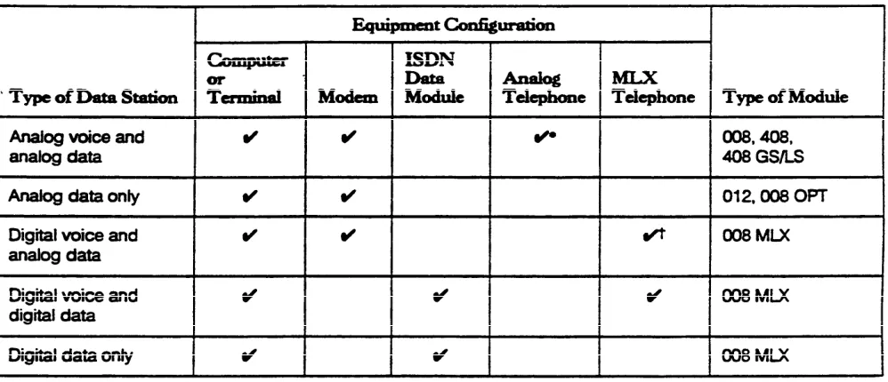
Depending on the type of voice and data transmission, data stations are configured with different combinations of data and telephone equipment (see Table 1-1).
Note: There is no analog voice and digital data configuration.
Table 1-1 Configurations of Data Stations
Data Communications
Components
Following are examples of configurations of voice and data equipment commonly connected to the system. The accompanying text describes the equipment and how it is connected to the control unit.
Individual Use Data Station
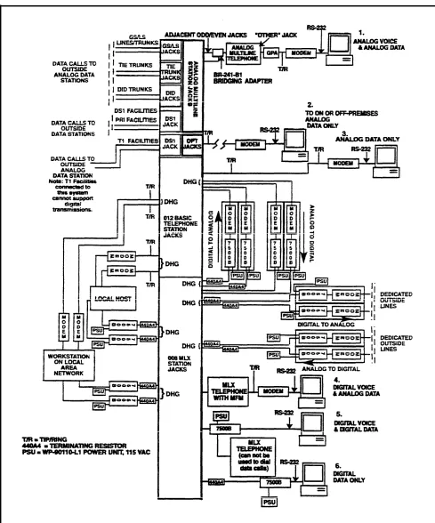
Figure 1-2 shows configurations for data stations intended for individual use.
Figure 1-2 Individual Used Data Station Configurations
1. 2. 3. 4. 5. 6.
Analog Voice and Analog Data Station includes a data terminal, a modem, and an analog multiline telephone. A GPA is required to supply the tip/ring (T/R) interface for the modem.
To provide the Simultaneous Voice and Data feature. two adjacent station jacks on a 408, 408 GS/LS, or 008 module must be assigned.
On- or Off-Premises Analog Data-Only Station Includes a data terminal and a modem. Connection to the control unit is through an off-premises telephone jack on a 008 OPT module.
Analog Data-Only Station includes a data terminal and a modem. Connection is through a jack on a 012 (basic telephone) module on the control unit.
Digital Voice and Analog Data Station includes a data terminal, a modem, and an MLX telephone. An MFM installed in the telephone is required to supply the T/R interface to the modem.
Digital Voice and Digital Data Station includes a data terminal, an lSDN 7500B Data Module, and an MLX telephone. The lSDN 75006 Data Module supplies the RS-232 interface to the data terminal. The data station connects through a jack on a 008 MLX module.
Digital Data-Station includes a data terminal and an ISDN 7500B Data Module. When the 7500B is installed without an MLX telephone, a 440A4 terminating resistor is required. One station jack on a 008 MLX module is assigned to connect this configuration.
Modem Pools and Data Hunt Groups
A modem pool (also called a conversion resource) is made up of one or more pairings of an ISDN 7500B Data Module and a modem. Modem pools provide resources that convert digital data signals to analog, or analog data signals to digital, and allow users with different types of data stations to communicate with each other.
A data hunt group (DHG) is a group of data stations of the same type (all analog modems or all digital ISDN 7500B Data Modules) or is a group of one or more modem pool pairings. A common extension number is assigned to each group —for example, extension 771 can be assigned to the data module DHG used to communicate with the local host computer, extension 773 can be assigned to the modem DHG used to communicate with the local host computer, extension 774 can be assigned to the data module DHG used to communicate with the workstation on a LAN, and extension 775 can be assigned to the modem DHG used to communicate with the workstation on a LAN.
DHGs allow sharing of data communication resources by connecting users in a round-robin fashion to the first available data station or modem pool pairing in the group. Specific lines/trunks can also be assigned to ring directly into the DHG so that outside callers can dial a published telephone number to reach the DHG.
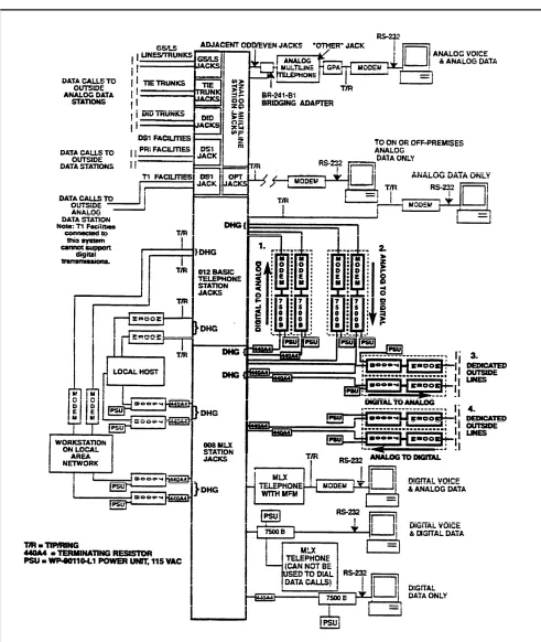
Figure 1-3 shows how modem pools assigned to DHGs can be configured to allow analog and digital stations to communicate with each other.
Figure 1-3 Modem Pools Assigned to Data Hunt Groups
1.
2.
3.
4.
Digital-to-Analog translates digital signals to analog signals for data calls made from a digital data station to an inside or outside analog station. In this configuration, the ISDN 7500B Data Modules are assigned to a DHG.
Analog-to-Digital translates analog signals to digital signals for data calis from an analog data station to an inside or outside digital data station. In this configuration, the modems are assigned to a DHG.
Digital-to-Analog (Outgoing) on Dedicated Outside Lines translates digital signals to analog signals for data calls from a digital data station to an outside analog station over analog dedicated outside lines. These lines are used solely for data communications. In this configuration, the ISDN 7500B Data Modules are assigned to a DHG.
Analog-to Digital (Incoming) on Dedicated Outside Lines translates analog signals to digital signals for data calls from an outside analog data station to an inside digital data station over analog dedicated outside lines. These lines are used solely for data communications.
Configurations 1 and 2 (digital-to-analog and analog-to-digital) use system lines; therefore, the modems and data modules must be connected directly to the control unit. Each modem is assigned to a jack on a 012 or 008 OPT module, and each ISDN 7500B Data Module is assigned to a 008 MLX module jack.
For configurations 3 end 4 (the digital-to-analog or analog-to-digital on a dedicated outside line), only the ISDN 7500B Data Module connects to the control unit via jacks on a 008 MLX module.
In all four configurations, a 440A4 terminating resistor is required when the 7500B is connected without an MLX telephone to the control unit.
Local Host Computer and LAN Workstation
Figure 1-4 shows data stations assigned to DHGs to provide access to a Iocal host computer and a workstation on a LAN.
1. Local Host Computer configuration includes a local host computer and the modems or ISDN 7500B Data Modules that connect the local host computer to the control unit.
The modems and data modules are connected to RS232 ports of the host computer. Each modem is assigned to a jack on a 012 module, and each ISDN 7500B Data Module is assigned to a 008 MLX module jack.
2. Workstation on LAN configuration includes a data terminal or computer (workstation) that is part of a LAN and modems and/or ISDN 7500B Data Modules. The LAN is either an interconnected chain of terminals or PCs that pass data to and from a mainframe computer or a network of interconnected computers.
In Figure 1-4, the modems and data modules are arranged in DHGs to allow a sharing of data communications equipment. Data station users
communicate with the local host computer or the workstation on the LAN by using the extension number assigned to the DHG.
Figure 1-4 DHGs Connected to Local Host Computer and LAN Workstation
System Features for Data
The following features are available to data station users through theCommunication
communications system software:■ ■ ■ ■ ■ ■ ■
Networking Capabilities
Modem Pool allows data communications between digital and analog data stations.
Data Hunt Group allows users to reach a group of similar (analog or digital) data stations or a group of one or more modem pool pairings via a common extension number.
Account Code Entry allows tracking of outgoing data calls for report used for billing, forecasting, or budgets.
Auto Answer All is used when an analog data station is connected to an analog multiline telephone via a General Purpose Adapter. It allows a modem with automatic answering capability to answer data calls when the user is away from the station.
Data Status is used when a data station includes an analog multiline or MLX telephone. It monitors when data equipment is in use.
Privacy prevents loss of data by ensuring that data transmission is not interrupted accidentally. Privacy for data calls is provided automatically on digital data stations but must be manually activated on analog data stations.
System Speed Dial and Personal Speed Dial permit quick dialing of frequently used numbers.
The system can connect to another system via the two control units or via tie trunks.
Control Unit to Control
This system’s control unit can connect to another system’s control unit in threeUnit
ways:■
■
■
from an off-premises telephone (OPT) line to a loop-start line/trunk (or vice versa) via analog facilities
via an analog tie trunk connected on a 400EM module
via a digital emulated tie trunk on a DS1 facility connected on a 100D module programmed for T1 type transmission. A back-to-back connection from one DS1 facility to the other can be used when the total cable distance is fewer than 1300 feet.
OPT/Loop-Start Connection
A 008 OPT module on system A’s control unit can be connected to a loop-start port on system B’s control unit. This enables the user on system B to access all the stations and facilitiess on system A. If system B has remote access, the user on system A can directly access stations and facilities on system B without operator intervention. Conversely, a loop-start port on system A can be connected to an OPT port on system B.
Note: If the systems are on the same premises, the connection can be made to any T/R port.
With the OPT/loop-start connection, glare is more frequent as the volume of calls increases. (Glare occurs when a user tries to make an outside call on a
line/trunk at the same time an incoming call is being received on that line/trunk.) In addition, if system B (the loop-start interface) does not have remote access. only the stations assigned to the loop-start facility on system B can be accessed by system A.
Analog Tie-Trunk Connection
In an analog tie-trunk connection, this systems 400EM module is connected to another system’s control unit. If both systems are on the same premises, this module can be connected directly to the other system if the other system has similar tie-trunk facilities.
For off-premises connection, the 400EM module can be connected via the telephone company’s facilities to another system.
The analog tie-trunk connection can be administered for two-way traffic or for one-way traffic (incoming or outgoing). The one-way mode prevents blocked calls caused by glare.
Digital Tie-Trunk Connection
The digital tie-trunk connection joins the DS1 facility (the 100D module) on the system to another system’s DS1 facility. If the other system is on the same premises, the connection is back-to-back. To reach a remote system, the DS1 facility connects via a channel service unit (CSU) to the telephone company’s facilities.
Tie-Trunk Networks
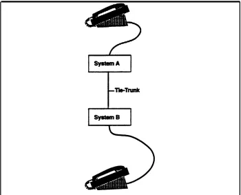
The tie-trunk networks that can be used with the system are tandem, and intertandem.Nontandem
The nontandem tie-trunk network is used primarily to connect station lines at both ends; it does not connect to another tie trunk (see Figure 1-5).
Figure 1-5 Nontandem Tie-Trunk Network
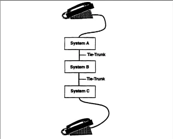
T a n d e m
The tandem tie-trunk network has a station on one system connected to a station on a third system via a tie-trunk connection in a second system. The tandem network also can be used to connect to an external facility in the third system, but the grade of service will be fair to poor if one or both tie trunks are analog (see Figure 1-6).
Figure 1-6 Tandem Tie-Trunk Network
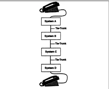
Intertandem
The intertandem tie-trunk network has a tandem tie trunk connected to tie trunks at both ends. it is not recommended for analog tie trunks (see Figure 1-7).
Figure 1-7 Intertandem Tie-Trunk Network
System Capacities
The communications system can be arranged as a stand-alone system or as part of a private network and comes in two sizes, large and small. The large system supports up to 224 jacks to connect 80 central office lines/trunks and 144 stations (such as telephones and fax machines), and the small system supports up to 80 jacks to connect 24 lines/trunks and 56 stations. The capacity of the system is determined by the size of the memory in the processor module (including the feature module) located in the control unit.
The large version of the system supports
■ up to 108 simultaneous two-party conversations (40 in the small version)
■ up to 80 line/trunk jacks (24 in the small version), including basic, DID, tie,
FX, WATS, and 800 service
■ up to 255 station endpoints (56 in the small version) that support a combination of
■ up to 144 physical station jacks (56 in the small version) for telephones
and adjuncts
■ up to 127 logical digital data ports (via ISDN 7500B Data Modules
connected to jacks on the MLX module) providing RS-232 connections to data terminals and personal or multiport computers
See “Capacities" in Chapter 6 for a full explanation of the small and large system capacities.
DS1 Capabilities
A Digital Signal 1 (DS1) is a transmission system that carries digital signals in the DS1 format. The outside DS1 facility connects to a channel service unit (CSU), which in turn connects to the 100D module. The CSU ensures that the transmission of the 100D module matches the transmission of the outside DS1 facility. The 100D module can be programmed to handle either T1 or ISDN-PRI service.
See "DS1 Facilities " in Chapter 4 for a full explanation of how the system works in DS1 format.
System Programming
The communications system can be programmed with options for
■ basic system operating conditions
■ system renumbering
■ settings for lines/trunks
■ telephones and operator consoles
■ adjuncts
■ applications
■ optional-features
The system can be programmed by using one of the following:
■ an MLX-20L telephone connected to the first MLX module in the control unit
■ a PC with System Programming and Maintenance (SPM) software connected
to the lower RS-232 port on the processor module
■ the built-in modem in the processor module, which permits remote
programming via the public network. (For example, the AT&T support personnel can access the system by using a PC with a modem and with SPM software; AT&T support personnel call the system and enter a password to gain access. The system must be programmed for Remote Access.)
The programming options are accessed from display screen menus. For more information, see the System Proogramming manual.
2
Introduction
This chapter describes the following types of features available with the communications system:
■
■
■
System features affect how the system operates and/or must be assigned through system programming.
Telephone features affect individuaI users (including system operators) and are either programmed through centralized telephone programming or by users from their telephones.
System operator features affect only system operators and are programmed either through centralized telephone programming or by system operators from their consoles.
The system also offers data features - features that can be programmed or used to make or receive data calls. Some of these features, such as Speed Dial, are also used to make or receive voice calls. Data-only and voice/data features are described in the Data Guide.
How the Information Is Presented
System, telephone, and system operator features are combined in this chapter and presented in alphabetical order. The information for each feature is presented under the following subheadings:
■
■
■
■
■
■
■
■
■
Extension Programming - the programming codes, feature codes, and digital/lSDN (MLX) telephone display labels that appear on the MLX telephone display while the feature is being programmed or used
Description - how the feature works and what it does for the user
Telephone Differences - differences in feature operation among telephone types
Mode Differences - functional differences of the feature in the Key, Hybrid/PBX, or Behind Switch modes of operation
Considerations - restrictions, capacities, and other information to consider before using or programming the feature
Feature Interaction — other features that must be used with, cannot work with, or modify the operation of the described feature
System Programming — the steps to activate the feature and the menu choices to reach the right screen from the System Programming menu. (See the Planning Guide [PBX or Key] for planning instructions and System Programming for system programming instructions.)
Hardware Requirements — hardware required to use features, including connectivity diagrams where applicable
Related Features — other features with similar functionality
Note: Subheadings that are not applicable are omitted-for example, if there are no mode differences, the "Mode Differences" subheading is omitted.
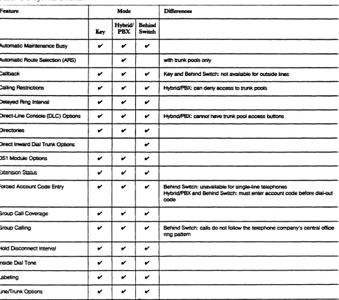
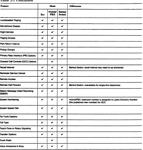
Feature Tables
Table 2-1 (System Features) and Table 2-2 (Telephone and System Operator Features) list all the features of the system.
System Features
System features affect how the system operates and/or must be assigned through system programming. Table 2-1 lists all the system features. the modes