Containment and Analysis Capability Insights Gained from Drop Testing
Representative Spent Nuclear Fuel Containers a
Dana K. Morton, Spencer D. Snow, Tom E. Rahl, and Dr. Arthur G. Ware
Idaho National Engineering and Environmental Laboratory, Bechtel BWXT, LLC, Idaho Falls, ID
ABSTRACT
The National Spent Nuclear Fuel Program (NSNFP), operating from the Idaho National Engineering and Environmental Laboratory (INEEL), developed the standardized Department of Energy (DOE) spent nuclear fuel (SNF) canister. This canister is designed to be loaded with DOE SNF (including other radioactive materials) and then be used during interim storage, during transportation to the nation's repository, and for final disposal at the repository without having to be reopened. The canister has been fully designed and has completed significant testing that clearly demonstrates that it can safely achieve its intended design goals.
During 1999, nine 457-mm diameter test canisters were fabricated at the INEEL to represent the standardized DOE SNF canister design. Various "worst case" internals were incorporated. Seven of the test canisters were 4.57 m long and weighed approximately 2721 kg, while two were 3.00 m long and weighed approximately 1360 kg and 1725 kg. Seven of the test canisters were dropped from 9 m onto an essentially unyielding flat surface and one of the test canisters was dropped from 1 m onto a 15-cm diameter puncture post. The final test canister was dropped from 61 cm onto a 50.8 mm thick vertically oriented steel plate, and then fell over to impact another 50.8 mm thick vertically oriented steel plate. This last test represented a canister dropping onto another larger container such as a repository disposal container or waste package. The 1999 drop testing was performed at Sandia National Laboratories (SNL). The nine test canisters experienced varying degrees of damage to their skirts, lifting rings, and pressure boundary components (heads and main body). However, all of the canisters were shown to have maintained their pressure boundary (through pressure testing). Four heavily damaged canisters were also shown to be leaktight via helium leak testing. Pre- and post-drop finite element (FE) analyses were also performed. The results clearly indicated that accurate predictions of canister responses to the drop tests were achieved.
The results achieved for the standardized canister can also be applicable to other well-constructed containers (canisters, casks, cans, vessels, etc.) subjected to similar loads. Properly designed containers can maintain a containment system after being subjected to dynamically induced high strains and FE computer analyses can accurately predict the resulting responses.
NSNFP OBJECTIVES
The Department of Energy's Office of Environmental Management (EM) establishes the methods to be employed in the treatment, handling, storage, and preparation for disposal of DOE SNF, including both current inventory and expected future receipts, as well as other radioactive materials. The NSNFP assists EM in implementing these methods. The mission of the NSNFP is to safely and efficiently manage DOE-owned SNF and prepare it for disposal at the nation's repository.
One of the goals of the NSNFP was to develop a container for DOE SNF. The objective was to seal the many types and varied geometries of DOE SNF in a finite number of these containers to simplify handling during initial interim storage, then during transportation to the nation's repository, and finally during the efforts necessary to place the DOE SNF into the repository for final disposal. The NSNFP worked with the DOE's Office of Civilian Radioactive Waste Management (OCRWM), the INEEL, the Hanford Site, Oak Ridge National Laboratory, Argonne National Laboratory, and the Savannah River Site to develop these containers, referred to as the standardized DOE SNF canisters. A standardized canister for DOE- owned SNF has the purpose of providing (1) a standard and easy-to-handle unit to confine DOE SNF, (2) durable units for storing SNF, (3) easily transportable units, and (4) ultimately, units for final disposal at the nation's repository, without the necessity of the DOE SNF being removed from the canister or reopening a sealed canister.
To maintain simplicity, efficiency, and to keep costs low, the intent was to have these canisters envelope the SNF but not provide numerous safety features, such as shielding. Other components (including the interim storage facilities, the transportation packagings, and the repository waste packages) could be relied upon to provide these other safety functions.
Although the goal was to shift various safety functions onto other facilities or components, the potential still exists that when these canisters are being handled by themselves, they could be accidentally dropped. This means that the standardized DOE SNF canister has to be sufficiently robust to withstand anticipated operational loads and at least confine the DOE SNF after an accidental drop event. Therefore, providing some means of protecting these canisters during potential drop events was a significant design consideration. However, the lack of shielding meant that workers could not be relied upon to easily a Work supported by the U.S. Department of Energy, Office of Environmental Management, under DOE Idaho Operations Office Contract DE-AC07-99ID 13727.
SMiRT 16, Washington DC, August 2001
Paper # 1787
attach and remove external impact limiters. In addition, the physical presence of external impact limiters could potentially impose unnecessary handling restrictions and excessive usage of limited space. Therefore, the use of removable external impact limiters was deemed undesirable.
CANISTER DESIGN
The design for the standardized DOE SNF canister had to consider a number of issues. The canister would have to be easy to incorporate into various proposed interim storage and transportation systems as well as the repository. The design had to consider loads due to accidental drop events during handling. The design also had to consider a number of unknown loads since a number of the DOE sites did not have finalized plans in place regarding interim storage. Transportation cask details were also not finalized. Therefore, the NSNFP decided to write a preliminary design specification [1] that would reflect a canister with a robust design as well as a number of significant repository requirements (though not yet finalized). This would allow the NSNFP to proceed with certain aspects of gaining repository acceptance of the standardized DOE SNF canister design. It would also permit initial contracts to be placed to begin the process of interim storage of DOE SNF.
With a clear focus on future use, the preliminary design specification requires the standardized DOE SNF canister to be N-stamped per the criteria of the American Society of Mechanical Engineers (ASME) Boiler and Pressure Vessel (B&PV) Code, Section III, Division 3 [2]. The basis for this requirement is that the standardized DOE SNF canister can then function (if necessary) as the inner containment system for transporting damaged SNF, based on the guidance provided in Section 4.5.1.3 of NUREG-1617 [3]. Because the current decision is to allow the various DOE sites to procure the standardized DOE SNF canisters on an as-needed basis over the next several decades, imposing ASME Section III criteria results in appropriate controls for the construction of these canisters.
The preliminary design specification was written to document the canister design (with drawings) as well as the basic loads and criteria necessary to achieve repository acceptance. This document was not written to be the Design Specification as identified in Section III, Division 3 of the ASME B&PV Code. It was written to be used by various interim storage and transportation personnel (as applicable) as a basis for the generation of the standardized canister Design Specification and the associated Design Report once storage or transportation details were finalized. The preliminary design specification also performs the important function of providing the common design basis for all standardized DOE SNF canisters, regardless of how each standardized DOE SNF canister is utilized at the various DOE sites during initial SNF loading, interim storage, or transportation to the repository. Regardless of the individual use history of each standardized canister, the repository can be assured of receiving a standardized DOE SNF canister that properly interfaces with facility lifting fixtures, a canister that properly fits in designated places, and a canister that will perform as expected in case of an accidental drop or other significant loading event.
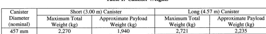
The standardized DOE SNF canister design has two nominal diameters (457 mm and 610 mm) and two nominal lengths (3.00 m and 4.57 m), and is made of 316L stainless steel. The nominal wall thickness is 9.53 mm for the 457-mm diameter canister, and 12.7 mm for the 610-mm diameter canister. Although a 344.8 kPa internal pressure was established for design conditions (151.7 kPa operational), the standardized DOE SNF canister actually has the capability of withstanding a much higher pressure limit (working pressure of about 2.41MPa). This is just one example of the robust design of the standardized DOE SNF canister. Maximum total loaded weight limits for all four canister geometries are listed in Table 1. Table 1 also lists the approximate payload limit for each canister, assuming the payload includes the internals (including the impact plates identified in Figure 1) and the DOE SNF or other radioactive materials.
Table 1. Canister Weights
Canister Diameter (nominal)
Short (3.00 m) Canister Maximum Total
Weight (kg) 2,270 457 mm
610 mm 4,080 3,433
Approximate Payload Weight (kg)
1,940
Long (4.57 m) Canister
Maximum Total Approximate Payload
Weight (kg) Weight (kg)
2,721 2,235
4,535 3,591
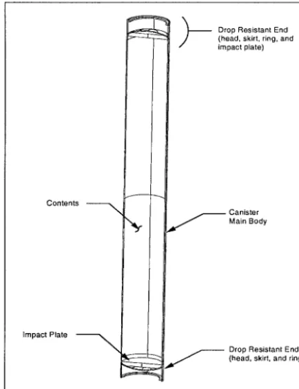
This canister design incorporates an integral energy-absorbing skirt (Figures 1 and 2) that deforms on impact during an accidental drop event, providing a significant amount of protection to the pressure boundary or containment system of the canister. The skirt helps to protect the canister containment system in virtually all accidental drop events by absorbing impact energy. Only when the canister impacts in a horizontal (fiat) orientation does the skirt not absorb significant energy. However, in horizontal orientations, the entire length of the canister is then able to absorb the drop energy. A deformed skirt can be removed if necessary without disrupting the canister containment system, enhancing the canister's ability to still fit into other containers.
Contents
Impact Plate
\
\
~ Drop Resistant End
---'--- (head, skirt, ring, and
impact plate)
.__._.__
Canister Main Body
Drop Resistant End (head, skirt, and ring)
Wall 9.53-mm Thick 316L SA-312
Impact Plate 50.8-mm Thick CS A-36
Flanged Head 9.53-mm Thick 316L SA-240
Lifting Ring ~ [
25.4-mm Wide Skirt
12.7-mm Thick 9.53-mm Thick
316L SA-240 316L SA-312
Figure 1. Canister Overall Design (Section View) Figure 2. 457-mm Canister Lower End Cross Section
DROP TESTING
In the initial design stages, it was determined that the standardized DOE SNF canister would not be able to satisfy ASME Code stress limits for a 9-m drop scenario. Therefore, it was recognized that actual testing could be used to demonstrate that the intended canister design was indeed robust and useable. The NSNFP decided to initiate a preliminary drop test program that could be used to develop and prove the concepts being incorporated into the standardized canister design. During late 1997 and 1998, a series of both small-scale and full-scale drop tests were completed at the INEEL. The results of these preliminary tests demonstrated that the proposed canister design adequately protected the pressure boundary or containment material and that the dropped test specimens could hold 172 kPa air pressure steady for one hour, and that adequate computer predictions using FE plastic analysis techniques could be performed. Results from this preliminary drop test program are explained in greater detail in the conference paper by S. D. Snow et al. [4].
With the success of the preliminary drop testing effort, the NSNFP proceeded with a larger testing effort that would provide qualified drop test data results acceptable to itself, DOE, OCRWM, and other regulatory agencies. During 1999, the NSNFP funded an effort to fabricate, at the INEEL, nine full-scale representative standardized DOE SNF canisters. Seven of the test canisters were 4.57 m long, and two were 3.00 m long. Qualified INEEL welders with qualified welding procedures using ASME B&PV Code, Section III approved materials built the test canisters using processes similar to nuclear vessel construction. Examinations to determine weld acceptance also followed ASME B&PV Code, Section III requirements. These 457-mm test canisters (loaded with carbon steel reinforcement bars to represent SNF) were drop-tested at Sandia National Laboratories (SNL) during the summer of 1999 and returned to the INEEL for post-drop examination and helium leak testing. SNL has a drop test facility in place, including an "essentially unyielding" impact surface.
Canister Internal Components
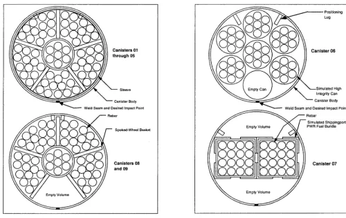
All nine of the test canisters had the 50.8 mm thick impact plates at both the top and bottom ends of each canister as shown in Figure 2. The seven 4.57 m long test canisters included a spoked-wheel divider and rebar (steel reinforcing bars) to simulate an internal structure and SNF loading. This is shown in Figure 3. This spoked-wheel divider was the most demanding of the expected internal component configurations because the spokes would tend to concentrate loads during a drop event over a smaller area of the canister body. Five of those seven test canisters also included a 4.7 mm thick interior sleeve. Two canisters (08 and 09) designated for puncture testing excluded the sleeve to demonstrate a robust design°
(HICs) [5] made of stainless steel pipe and rebar. These are shown in Figure 4.
C a n i s t e r s 01 o u g h 05
. . . .
Canister Body Weld Seam and Desired Impact Point
Rebar
O
' ~ ) I Spoked-Wheel Basket
Ca;i;9rs 08
~ Positioning
Lug
t e r 06
~ \ Empty Can ) / A ~---Simulated High
~ , . , ~,,,,~ J ~ ~ Integrity Can
""-" Canister Body Weld Seam- and Desired Impact Point
~ Rebar
~ ~ /--- Simulated Shippingport
~ , ,
Emp~Volume,
/ ~ '
PWR Fuel Bundle(5oo
o o o
8 8
c,ns,.r0,
E pty
Figure 3. Long Test Canister Internals Figure 4. Short Test Canister Internals
Drop Test Details
A summary of the test canister configurations and intended impact orientations is given in Table 2. The target at the SNL drop test facility included a flat 101.6 mm thick (at the thinnest location) steel plate imbedded in heavily reinforced concrete [about 9.1x10⁵ kg total weight]. The design of the facility provided the desired "essentially unyielding surface."
Table 2. Test Canister Configurations and Orientations
Canister No.
01
Length
(in)
09
Total Weight (kg) 4.57
Impact Angle (degrees)
4.57 90
2737
Drop Height
(m)
2760
02 4.57 6 2698 9
03 4.57 90 2719 9
04 4.57 45 2719 9
05 4.57 80 2706 9
06 3.00 90 1725 9,
07 3.00 90 1360 9
08 4.57 0 2709 0.61
The drop event simulated by canister 09 consisted of a 1-m drop, with the test canister in a horizontal orientation, onto a 15-cm diameter steel bar welded to the steel surface. The center-of-gravity of the test canister was centered above the bar before the drop. The drop height and puncture bar (or post) dimensions were chosen to follow that specified by the Code of Federal Regulations [6] for transportation packages (10 CFR 71.73).
Analytical Modeling
The test canisters were modeled and evaluated using the ABAQUS/Explicit software [7]. This software is a sophisticated FE analysis program designed specifically to evaluate dynamic events. It is very efficient for highly nonlinear problems involving changing contact conditions such as experienced during an impact event of a deformable canister. Details of the modeling and analysis of these canisters are given in another paper by S. D. Snow et al. [8].
Analytical vs. Actual Deformation Results
Details of the analytical versus actual deformation results are also found in Reference [8]. Many dimensions could have been compared between the actual dropped test canisters and the computer results. However, a limited number of specific dimensions were chosen for comparison that would provide significant indications of the test canister's response during the drop event. These specific dimensions included the amount of skirt deformation at the point of impact, the amount of ovalization of the skirt or canister body, the depth of the puncture bar deformation, etc. Only five test canister deformation comparisons will be discussed herein due to space limitations.
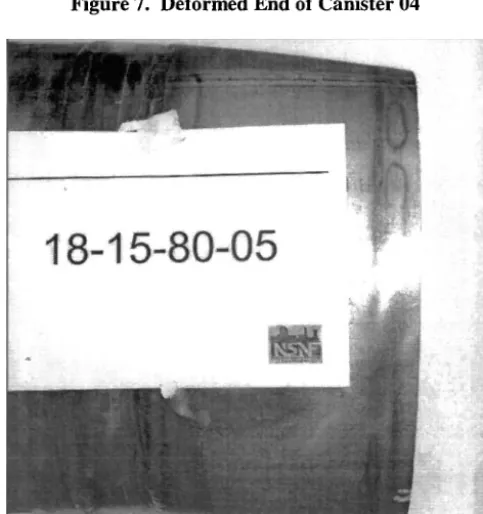
Test canister 01 was oriented vertically (0 degrees) and dropped 9 m. Figures 5 and 6 show that the FE model deformations matched very well with those of the actual test canister at the maximum skirt bulge and the amount of axial skirt compression (within 4%). However, the analytical predictions conservatively predicted an inward skirt deformation which the actual canister did not experience. This difference was attributed to residual weld stresses (not considered in model) and the skirt not being perfectly round, resulting in slightly differing buckling patterns. Test canister 04, dropped from 9 m, was oriented at 45 degrees off-vertical. Figures 7 and 8 show that the FE model deformations matched very well (within 6%) with those of the actual test canister. This was also the case with test canister 05, which was dropped from 9 m oriented at 80 degrees off-vertical. This test simulated the expected worst-case slapdown event on the test canister. Figures 9 and 10 show an excellent match (within 4%) between the FE model and the actual canister. Note the head bulge in response to the edge flattening on impact shown in the FE model. This was also seen in the actual canister. [That head bulge also occurred on the 90 degree drop orientations of canisters 03, 06, and 07, but was more pronounced for canister 05 (80 degree drop angle).] Test canister 08 was dropped from 61 cm onto a 50.8 mm thick vertically oriented plate. Figure 11 shows the resulting indentation on the skirt from the initial vertical impact and Figure 1:] shows the essentially identical deformation match. Test canister 09 was dropped from 1 m onto a 15-cm diameter solid steel post. Figures 13 and 14 show that the FE model deformation pattern was essentially the same as that of the actual canister. However, the analytically predicted maximum deformation depth was over-estimated by nearly 16 mm.
Pressure and Leak Testing
After the nine test canisters were dropped, each canister was pressurized with air to 344.8 kPa using the threaded plug on the top head of each canister. The pressure supply was then disconnected from the canisters and a pressure gauge was monitored for one hour. In every case the test pressure remained constant (no measurable loss in pressure) for the one hour monitoring period. This showed that the pressure boundary had been maintained for all canisters after the drop tests.
n ~ ~ ~ l l ~ l ~ l l | l l |
~-
|ll tliIII'i]HT[I I I I I ~ I I, I I I I I I I I~ I1'HUJHtTTI ~ t t ~,il I t t .', i ~, t ~ t Ih'll'l'Hll-l.$~l LL I i li~ I~,1 li II II ~II lllflHt]~ t IIIttlllll!!!! ~ I ,l[It..,lh"tl?i~ I I I', I I I I I I I I I [ I I Ill .t!t_WH'tt, TFl I I I I II, II I I, I ~ I I I ~ Iflli~l Jiiiiiiiiiiiii
IIIIIIT'P~III I ',It tl II II It II I I/lllltllll~lt ~ It'll It ISt',l~l ffTHttlllllS I II IIIIJ, I It II II h~._! !!iJ] HIJIII I I II II IIII ~ 1 1 I%111111111111 ~ ~ ~ , i', t J, i ~ , H.~'lfil.~d'rT-TT[Tm II It lit ~ l l t t t t t l l l
[/J~-~H]ETT~II I i I I I ~ I I I ITIIII~1t~]-I-ETI ~ I ~ 1% I I I ~ I P~'~I[L(~LEr~TT~ I I I I I I I I I ~rl~rt~[TT~ I I I I I I I I I I I I ~ 1 1 1 1 1 1 1 1 1 1
~i!~',~',~',~
Figure 7. Deformed End of Canister 04
!
Figure 8. Deformed FE Canister Model 04
,,,
i: 2
'
,,,"'
iiiilfif i r r,i i'
'
iiL'""-
,tll~ NlttN~I II~E ~ 1 1 IIIIIII1'1'1'1'1'1 I'1' Iltlllll.l.l.J I I I]_' ; 1 1 1 1 - ~ 1 I$11111121'.1111111 ~.'J~
' " l l l l " ~ l l l II'li'l',lll'l ['I1
,llll ~ l l l I l l ['.lJ[ll.I ll] illll ~ l l l l l l l l l i l i l ] I l l l l [i'! 1111~ ~ l l J i ~ l l l I I I I I I'. I i I ] [ 11iI ,~J_~
llllll_ ~ l I I I I ~11'.:t ] I I i I I i I iJJJ_ ~IIIIL ~ l l ~ l l l l l l ' - I ] I I ! l l ! l l ~1' Ill iillllL ~ l l l l l l l I'.l]tl!ll',II!l'_
II illlll_ ~ l l l l l l l l ~ ' , I I : l ! l l I I l _ ' _ L ' _ Ill "~llIJ ~ l l l l l t l $ l / l r l I'11111 I.. III IlllJ ~ l l l l l l l l l l l l I I't'li/_ Ill Illl! ~ l l l l l l l l l i l [ ' ~ , ~ I:1 Iil Ill IIIL 1 ] ~ l l l l I ~ ' l lil I I Ill__
III I ~ I L ~ 1 1 1 1 ~ t ~ 1 1 1 1 : 1 I!1 l i l I l l _ I I I L ~ 1 1 1 1 1 1 1 1 1 1 1 ~ t I I I II1__ II ,II_L [ J ~ l l l l , , l l l l , , , I I , I I I l l
~ L [ ~ l f l l l l l l ~ l l l I / _ I I I " . U ~ . J
II
I I I _ L ! ~ ' 1 1 1 1 1 t 1 1 1 1 1 1 1 1 I I I I~1 I I d I I I l L ~ i l l l l l l l l I I I I I I I I I , I t l I I : J I I I I l L ~ ' ~ 1 1 1 1 1 1 1 1 1 1 1 1 , I I I I I I I i i II_L ~ . . . I ~ I ~ I l ] I r l : I I IFigure 9. Deformed End of Canister 05
i8.15_PW_08
I
... ~:
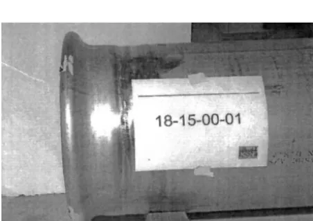
Figure 11. Deformed Skirt of Canister 08
Figure 10. Deformed FE Canister Model 05
Figure 13. Deformed Body of Canister 09 Figure 14. Deformed FE Canister Model 09
Four of the test canisters, including the most highly strained canister (05) and three others representing a variety of impact angles or drop scenarios, were helium leak tested (after the drop and pressure testing) at the INEEL. Test canisters 01, 04, 05, and 09 were helium leak tested and found to have a maximum leak rate of less than l x l 0 7 standard cubic centimeters per second. This was considered leaktight [9] and additional proof that containment was maintained.
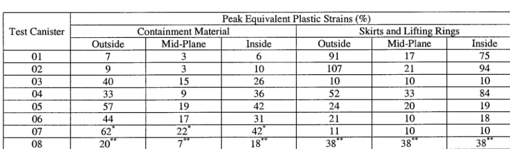
Calculated Strains
The previous section showed that the FE models performed well in predicting the deformed shape of the test canisters. The calculated peak equivalent plastic strain, which is a measure of the accumulated plastic strain in all directions at a location, was summarized for each model. Table 3 lists the analytically predicted peak equivalent plastic strains in the canister models. The peak strain at the outside surface did not necessarily occur at the same location as the peak strain at the inside surface or mid-plane surface.
Test Canister
06
Peak Equivalent Plastic Strains (%)
Containment Material Skirts and Lifting Rings Outside Mid-Plane Inside Outside Mid-Plane
01 7 3 6 91 17
02 9 3 10 107 21
03 40 15 26 10 10
04 33 9 36 52 33
05 57 19 42 24 20
44 17
62* 20**
31 22*
7**
42* 18"*
Table 3. Calculated Peak Equivalent Plastic Strains
21 11 38"* 07
10 10 38** 08
09 39 14 40 - -
Inside 75 94 10 84 19 18 10 38"*
*Peak strains due to conservative modeling of internals as discussed in text. Actual peak straining estimated to be below that reported for canister 06.
**Reported peak containment material strains due to impact with second vertical plate. Peak skirt and lifting ring strains due to impact with first vertical plate.
The next largest surface strain for any canister pressure boundary component was 57%. This occurred on the upper head of canister 05 due to the slapdown event. The maximum mid-plane strain for any canister containment material was 19%. This also occurred on the upper head of canister 05.
F U T U R E PLANS
The drop testing performed to date reflects a "beginning of life" situation with respect to the material properties. Additional material testing and drop testing are planned in order to document the anticipated performance of an aged standardized DOE SNF canister during an accidental drop event.
C O N C L U S I O N S
The repository has accepted the design of the standardized DOE SNF canister and has now incorporated it into their project documentation. The results of the drop testing performed to date clearly show that the design of the standardized DOE SNF canister is robust and that its containment system can indeed remain intact and functional, even after an accidental drop event. Helium leak testing has shown that leaktight conditions can be achieved. In addition, FE computer analyses can be performed that adequately predict the structural responses of these canisters. This is important for future structural evaluations that were not specifically tested. Therefore, with the standardized DOE SNF canister, the NSNFP has provided the DOE complex with an important tool to safely store, transport, and dispose of DOE SNF.
The results achieved for the standardized canister can also be applicable to other well-constructed containers (canisters, casks, cans, vessels, etc.) subjected to similar loads. Properly designed containers can maintain a containment system after being subjected to dynamically induced high strains and FE computer analyses can accurately predict the resulting responses.
NOTICE
This paper was prepared as an account of work sponsored by an agency of the U.S. Government. Neither the U.S. Government nor any agency thereof, or any of their employees, makes any warranty, expressed or implied, or assumes any legal liability or responsibility for any third party's use, or the results of such use, of any information, apparatus, product or process disclosed in this report, or represents that its use by such third party would not infringe privately owned rights. The views expressed in this paper are not necessarily those of the U.S. DOE.
R E F E R E N C E S
1. U.S. Department of Energy, Preliminary Design Specification for Department of Energy Standardized Spent Nuclear Fuel Canisters, DOE/SNF/REP-011, Revision 3, Volumes I and II, August 17,1999.
2. American Society of Mechanical Engineers, Boiler and Pressure Vessel Code, Section 111, Division 3, 1998 Edition.
3. U.S. Nuclear Regulatory Commission, Standard Review Plan for Transportation Packages for Spent Nuclear Fuel, NUREG-1617, March 2000.
4. Snow, S. D., Morton, D. K., Ware, A. G., Rahl, T. E., and Smith, N. L., "Analytical Evaluation of Preliminary Drop Tests Performed to Develop a Robust Design for the Standardized DOE Spent Nuclear Fuel Canister", 1999 ASME PVP Conference, Boston, Massachusetts, August 1-5, 1999, PVP-Vol. 390, pp. 69-80.
5. Spears, R. E., "Elastic-Plastic Drop Analysis Using Finite Element Techniques", 1999ASME PVP Conference, Boston, Massachusetts, August 1-5, 1999, PVP-Vol. 390, pp. 57-67.
6. Code of Federal Regulations, Title 10, Part 71, January 1, 1999 Edition.
7. ABAQUS~licit User's Manual, Volumes I and I1, Version 5.8, Hibbitt, Karlsson & Sorensen, Inc., 1080 Main Street, Pawtucket, RI, 1998.
8. Snow, S. D., Morton, D. K., Ware, A. G., Rahl, T. E., and Smith, N. L., "Analytical Evaluation of Drop Tests Performed on Nine 18- inch Diameter Standardized DOE Spent Nuclear Fuel Canisters", 2000 ASME PVP Conference, Seattle, Washington, July 23-27, 2000,
PVP-Vol. 408, pp. 97-106.
9. American National Standards Institute, American National Standard for Radioactive Materials - Leakage Tests on Packages for Shipment, ANSI N14.5-1987.