IJEDR1402059
International Journal of Engineering Development and Research (www.ijedr.org)1635
Coordination of overcurrent relay using Hybrid
GA-NLP method
1
Sanjivkumar K. Shakya,
2Prof.G.R.Patel
1P.G. Student, 2Assistant professor
Department Of Electrical Engineering
Sankalchand Patel College Of Engineering,Visnagar(Gujarat-India) 1[email protected], 2[email protected]
______________________________________________________________________________________________________
Abstract—the overcurrent relays are major protection devices in distribution system. The relays in the power system have
to be coordinated so as to and hence to avoid unnecessary outage of healthy part of the system. This paper presents hybrid genetic algorithm (GA)-nonlinear programming approach to find optimal value of Time multiplier setting(TMS) and Plug setting(PS) of overcurrent relay. It also presents load flow and short circuit analysis of 9 bus ring main system using Electrical Transient Analysis Program (ETAP).
Key words —Overcurrent relay, TMS, PS Constraints, Genetic Algorithm ,MATLAB optimization toolbox.
1. INTRODUCTION
Overcurrent relays are used as back up relays. The problem of coordinating protective relays in protection systems consists of their suitable settings such that their fundamental protective function is met under the requirements of sensitivity, selectivity ,reliability, and speed [6].
A typical power system may consists of hundreds of equipment and even more protection relays to protect the system. A relay must get sufficient chance to protect the zone under its primary protection. Only if the primary protection does not clear the fault, the backup protection should takeover tripping. If backup protections are not well coordinated, mal-operation can occur and, therefore, overcurrent relay coordination is a major concern of power system protection[5].
In this paper the problem of determining the optimum values of TMS and PS of OCRs is formulated as NLPP(Non linear programming problem) and GA-NLP method is used to find the optimum solution.GA is a multipoint search method but sometimes, it converging to the values which may not be optimum, and NLP methods, being single point search methods, have a drawback of being trapped in local optimum point, if the initial choice is nearer to the local optimum. NLP method gives global optimum solution, if proper initial choice is made. GA searches a large solution space. To make use of the advantages of GA and NLP methods, and at the same time to overcome the drawbacks of these methods, GA has been used to determine the initial value of TMS and PS of OCRs. These values are then used as initial choice in NLP method, which gives the global optimum solution[1].
2. GENERIC PROBLEM FORMULATION
The coordination problem of directional OCRs in a ring fed distribution systems, can be stated as an optimization problem, where the sum of the operating times of the relays of the system, is to be minimized[1][2][3].
∑
Where,
m=number of relays;
ti,k=operating time of relay Ri, for fault at k;
Wi=weight assigned for operating time of the relay Ri ;
In the distribution system, since the lines are short and are of approximately equal length, equal weight (=1) is assigned for operating times of all the relays. The objective of minimizing the total operating times of relays is to be achieved under five sets of constraints, as discussed in the following sections.
Constraint Set I-Coordination Criteria
IJEDR1402059
International Journal of Engineering Development and Research (www.ijedr.org)1636
is backup relay for the same fault, then the coordination constraint can be stated as[1][2][3].(1.2) Where
ti,k=operating time of the relay Rj, for fault at k;
tj,k=operating time of back up relay Ri, for the same fault at k; = CTI.
Constraint Set II-Bounds on Relay Operating Time
Howsoever fast we want the relay to operate; it needs a certain minimum amount of time to operate. Also a relay should not be allowed to take too long time to operate. Constraint imposed because of restriction on the operating time of relays can be mathematically stated as[1][2][3].
(1.3)
Where
ti,min=minimum operating time of relay at location i for the fault at point in the zone of operation. ti,max= maximum operating time of relay at location i for the fault at point in the zone of operation.
Constraint Set III-Bounds on the TMS of Relays
The TMS of relays directly affect the operating time of relays, which puts bounds on TMS of relays. It can be stated as[1][2][3].
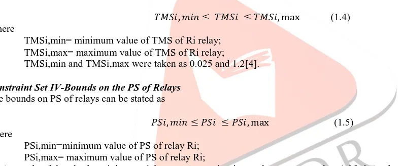
(1.4) Where
TMSi,min= minimum value of TMS of Ri relay; TMSi,max= maximum value of TMS of Ri relay;
TMSi,min and TMSi,max were taken as 0.025 and 1.2[4].
Constraint Set IV-Bounds on the PS of Relays
The bounds on PS of relays can be stated as
(1.5) where
PSi,min=minimum value of PS of relay Ri; PSi,max= maximum value of PS of relay Ri;
As a rule of thumb, the minimum pickup current setting is equal to or greater than 1.25 times the maximum load current. This is to ensure that the relays will not mal-operate under normal load and small amount of overload conditions. Similarly maximum pickup current setting is less than or equal to 2/3rd of the minimum fault current. This ensures that the relay is sensitive to the smallest fault current[1][2][3].
Constraint Set V-Relay Characteristics
In this paper, a nonlinear and popular OCRs characteristic function (which has been reported in most of the literature) as shown in (6.6), has been considered. The values of 𝝺 and 𝞬 are detailed in Table I [1][2][3].
(1.6)
where
top= relay operating time
Irelay= current through the relay operating coil PS= plug setting
TMS= time multiplier setting.
Table :I.Values of 𝝺 and 𝞬 for different types of OCRs.
OCR Type 𝝺 𝞬
Instantaneous Operating time is fixed. No intentional time delay is added.
Definite Time Operating time is pre-decided and fixed. Intentional time delay may be added. Inverse Definite
Minimum Time (IDMT) 0.14 0.02
IJEDR1402059
International Journal of Engineering Development and Research (www.ijedr.org)1637
Extremely Inverse 80 2
3. GENETIC ALGORITHM
The genetic algorithm (GA) is a randomized search and optimization technique guided by the principle of natural genetic systems. Genetic algorithms use vocabulary borrowed from natural genetics. A genetic algorithm starts with an initial set of random solutions, the population. Each individual in the population is a chromosome, representing a solution to the problem. A chromosome is a string structure, typically a concatenated list of binary digits representing a coding of the control parameters of a given problem. The chromosomes evolve through successive iterations called generations[7].
Genetic operators
Reproduction: In this process the individuals are selected based on their fitness values relative to that of the population. Thus individuals (chromosomes) with higher fitness values have a greater chance of being selected for mating and subsequent genetic action. Consequently, highly fit individuals live and reproduce, and less fit chromosomes die.
Crossover: After reproduction, “crossover” operation is implemented. Crossover is an operator that forms a new chromosome, called “offspring” ,from two “parent”chromosomes by combining part of the information from each.Crossover is implemented in two steps. First, two individuals strings are selected from the mating pool generated by the reproduction operator. Next, a crossover site is selected at random along the string length, and the binary digits are swapped between the two strings following the crossover site. The offspring obtained from crossover are placed in the new population.
Mutation: This process is applied after crossover. A mutation is the occasional, random alteration of a binary digit in a string. Thus in mutation a 0 is changed to 1,and vice versa, at a random location[5][7].
4. NONLINEAR PROGRAMMING PROBLEM
In an optimization problem, if the objective function and/or constraint/s are nonlinear ,the problem is called nonlinear programming problem (NLPP). In case of OCR coordination problem the relay characteristic, described by(1.6),is nonlinear in nature because of which the objective function, the operating time constraints, and the coordination constraints become nonlinear.
Various methods are available to solve the constrained NLPP. In this paper, the function available in MATLAB optimization toolbox has been used to find the global optimum solution of the relay coordination problem.
5. SIMULATION AND RESULTS.
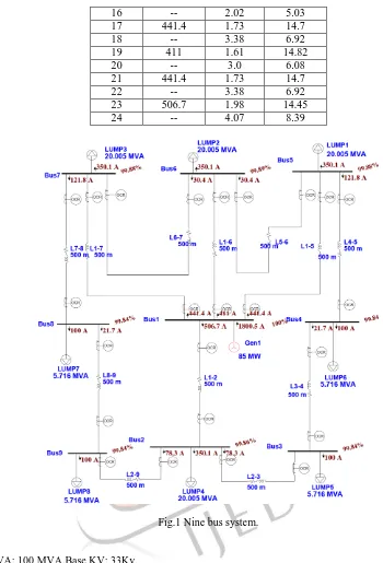
The Hybrid GA -NLP method was tested for Nine bus system as shown in figure1..In this twenty four relays have been considered as numerical relay with standard IDMT characteristics. A multi loop distribution system with 9-buses, and 24 relays, as shown in figure1.
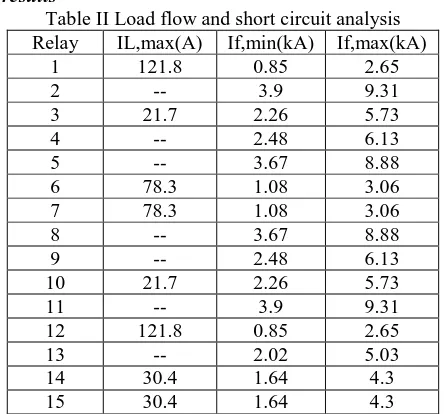
Load flow and short circuit analysis results shown in table II. Load flow study is necessary to find out plug setting of relay and short circuit study is essential to find plug setting multiplier (PSM) of relay. Then using this PSM, Time multiplier setting of relay is obtained . therefore, load flow and short circuit analysis is necessary in relay coordination.
6. SIMULATION AND RESULTS
Load flow and short circuit analysis results
Table II Load flow and short circuit analysis Relay IL,max(A) If,min(kA) If,max(kA)
1 121.8 0.85 2.65
2 -- 3.9 9.31
3 21.7 2.26 5.73
4 -- 2.48 6.13
5 -- 3.67 8.88
6 78.3 1.08 3.06
7 78.3 1.08 3.06
8 -- 3.67 8.88
9 -- 2.48 6.13
10 21.7 2.26 5.73
11 -- 3.9 9.31
12 121.8 0.85 2.65
13 -- 2.02 5.03
14 30.4 1.64 4.3
IJEDR1402059
International Journal of Engineering Development and Research (www.ijedr.org)1638
17 441.4 1.73 14.7
18 -- 3.38 6.92
19 411 1.61 14.82
20 -- 3.0 6.08
21 441.4 1.73 14.7
22 -- 3.38 6.92
23 506.7 1.98 14.45
24 -- 4.07 8.39
Fig.1 Nine bus system.
System Data[1]: Base MVA: 100 MVA,Base KV: 33Kv.
Generator :100MVA,33kV,impedance(0+j0.1)p.u. Line:impedance(0+j0.2)p.u.
Value of TMS and PS for Relay Using GA
Table III Value of TMS and PS using GA
Relay TMS PS
1 0.42856681 0.3045
2 0.22843018 0.79206292 3 0.41170231 0.37423044 4 0.25420445 0.45091937 5 0.20047607 0.57773404
6 0.44669954 0.1957
7 0.69659217 0.34251338
8 0.24887618 1.1957
IJEDR1402059
International Journal of Engineering Development and Research (www.ijedr.org)1639
10 0.31378115 0.7754257311 0.85083926 0.42765951 12 0.28712232 0.41591235
13 0.26947223 1.242
14 0.37625599 0.076
15 0.64021519 0.09787578
16 0.74315728 0.076
17 0.04581303 2.1092373 18 0.14841309 2.30721115 19 0.12374224 1.0275 20 0.13432428 1.88637651 21 0.05296006 1.49964654
22 0.275 1.9652095
23 0.14927677 1.2667 24 0.17153939 1.26767656
Value of TMS and PS for Relay using Non linear Programming
Table IV Value of TMS and PS using NLP
Relay TMS PS
1 0.14218 0.292967 2 0.244061 0.307023 3 0.266857 0.111876 4 0.271037 0.113228 5 0.305874 0.119627 6 0.176873 0.193896 7 0.177401 0.193973 8 0.270853 0.207967 9 0.237724 0.208825 10 0.269324 0.111873 11 0.317637 0.123943 12 0.147803 0.294239 13 0.214765 0.296363 14 0.273899 0.088835 15 0.241363 0.089632 16 0.222187 0.100992 17 0.054903 1.098766 18 0.106743 1.104091 19 0.047693 1.02476 20 0.10256 1.027923 21 0.057931 1.098846 22 0.113139 1.10455 23 0.055947 1.26251 24 0.114962 1.267666
IJEDR1402059
International Journal of Engineering Development and Research (www.ijedr.org)1640
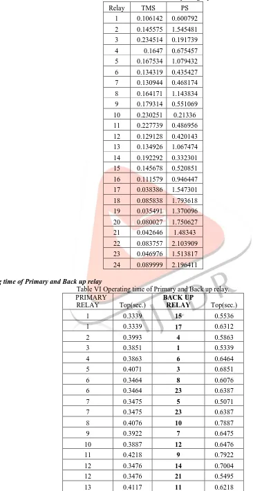
Table V Final value of TMS and PS for Relay using Hybrid GA-NLP.Relay TMS PS
1 0.106142 0.600792 2 0.145575 1.545481 3 0.234514 0.191739 4 0.1647 0.675457 5 0.167534 1.079432 6 0.134319 0.435427 7 0.130944 0.468174 8 0.164171 1.143834 9 0.179314 0.551069 10 0.230251 0.21336 11 0.227739 0.486956 12 0.129128 0.420143 13 0.134926 1.067474 14 0.192292 0.332301 15 0.145678 0.520851 16 0.111579 0.946447 17 0.038386 1.547301 18 0.085838 1.793618 19 0.035491 1.370096 20 0.080027 1.750627 21 0.042646 1.48343 22 0.083757 2.103909 23 0.046976 1.513817 24 0.089999 2.196411
Operating time of Primary and Back up relay
Table VI Operating time of Primary and Back up relay. PRIMARY
RELAY Top(sec.)
BACK UP
RELAY Top(sec.)
1 0.3339 15 0.5536
1 0.3339 17 0.6312
2 0.3993 4 0.5863
3 0.3851 1 0.5339
4 0.3863 6 0.6464
5 0.4071 3 0.6851
6 0.3464 8 0.6076
6 0.3464 23 0.6387
7 0.3475 5 0.5071
7 0.3475 23 0.6387
8 0.4076 10 0.7887
9 0.3922 7 0.6475
10 0.3887 12 0.6476
11 0.4218 9 0.7922
12 0.3476 14 0.7004
12 0.3476 21 0.5495
IJEDR1402059
International Journal of Engineering Development and Research (www.ijedr.org)1641
14 0.4004 21 0.7495
15 0.3536 13 0.6117
15 0.3536 19 0.7883
16 0.3227 2 0.6993
16 0.3227 17 0.5312
17 0.3312 --
18 0.2881 2 0.5993
18 0.2881 15 0.5536
19 0.2883 --
20 0.2835 13 0.4917
20 0.2835 16 0.4927
21 0.3495 --
22 0.3054 11 0.5218
22 0.3054 14 0.6004
23 0.3387 --
24 0.3036 5 0.7071
24 0.3036 8 0.7076
7. CONCLUSION
The values of TMS and PS for each relay of the Nine bus distribution system without DG using only genetic algorithm technique were not optimal. Optimization terminated and no feasible solution found using NLP method for the same system.By using hybrid GA method a feasible solution is achieved with minimum objective function value. The optimal values of TMS and PS for 9-bus distribution system found using hybrid GA-NLP approach.
8. REFERENCES
[1] Prashant Prabhakar Bedekar,Sudhir Ramkrishna Bhide,”Optimum Coordination of Directional overcurrent relays using the Hybrid GA-NLP Approach”,IEEE Transactions on Power delivery,vol.26,No.1,January 2011.
[2] P.P. Bedekar, Sudhir Ramkrishna Bhide, Optimum coordination of overcurrent relay timing using continuous genetic algorithm, Expert system with application 38,2011.
[3] K. A. Waleed, N. H. Zeineldin, Optimal protection coordination for microgrids with grid connected and islanded capability, IEEE Trans. Ind. Electronis., vol. 60,no.4, pp. 16681677, Apr. 2013.
[4] S. A. Soman, Lectures on Power System Protection module 4 & 5. [Online]. Available: www.cdeep.iitb.ac.in/NPTEL
[5] Prashant P. Bedekar, Sudhir R. Bhide, Vijay S. Kale” Optimum coordination of overcurrent relays in
distribution system using genetic algorithm” Third International Conference on Power Systems, Kharagpur, INDIA December 27-29,ICPS – 247,2009.
[6] Bhuvanesh Oza, Nirmalkumar Nair, Rashesh Mehta, Vijay Makwana, "Power System Protection and Switchgear" Tata McGraw Hill Education Private limited,New Delhi, 2010.pp 1-50, 175-270.