Nonlinear Sliding-Mode Control of Feed-Drive
Systems With Reduction in Energy
Consumption and Chattering Avoidance
Koshy Thomas1, Jaseena Sayed2
Assistant Professor, Dept. of EEE, TKM College of Engineering, Kollam, Kerala, India1 PG Student [IIC], Dept. of EEE, TKM College of Engineering, Kollam, Kerala, India2
ABSTRACT: Machine tools are extensively used worldwide, excessive energy consumed in machining by feed-drive systems is an important issue faced by most electro-mechanical industries. This paper presents a novel sliding-mode controller with a Nonlinear sliding surface (NLSS) for enhancing the performance of Ball Screw driven mechanism actuated by servodrives. Unlike the conventional sliding mode control design, the proposed NLSS varies according to the output (controlled variable) so that the damping ratio of the system can be changed from its initial low value to its final high value. Hence, it allows a closed-loop system to achieve small settling time, preferably without overshoot, resulting in small energy consumption. In spite of this, one of the main hindrance in the implementation of SMC is the chattering. It is undesirable, since it involves extremely high control activity, and furthermore may excite high-frequency dynamics neglected in the course of modeling. Therefore it is important to avoid control chattering by providing continuous or smooth control signal. Simulation results shows that the proposed approach reduces the control input variance and consumed energy compared to linear sliding surface and also considered chattering avoidance in control input.
KEYWORDS: Energy saving, feed-drive system, non linear sliding surface ( NLSS) ,Chattering.
I.INTRODUCTION
Ball Screw drives have been widely used in many industrial applications such as in most electromechanical and robotics system, where both high speed and positioning accuracy are required. Because most of these applications are used all over the world day and night, a large amount of energy is consumed by these applications. Hence reduction of electrical energy consumed by feed-drive systems has become an important issue in recent years.
II.SYSTEM MODELING AND CONTROLLER DESIGN
System Modeling
Fig. 1. Typical ball-screw feed-drive system.
Consider a typical ball-screw feed-drive system, which is shown in Fig. 1. Motor driver provides sufficient power to the dc servomotor, which is used to drive the feed-drive system. The screw-nut mechanism converts the servomotor rotational motion into a linear motion and moves the table towards the reference point. Generally feed-drive system is represented by the following second-order system.
d
f
x
g
x
m
(1)
where m( > 0), g(≥ 0), d, and f are the mass of the load, viscous friction coefficient, disturbance with known bounds, and driving force along the drive axis, respectively, and x is the position of the feed drive. The motor dynamics for driving the feed-drive system is described as follows:
u
h
n
(2)where θ, n(> 0), h(≥ 0), τ , and u are the rotational angle of the motor, motor inertia, motor viscous friction coefficient, torque needed to drive the feed-drive system, and motor input voltage, respectively. Here, u (in volts) is the control signal applied to the motor armature which produces the current resulting in the motor torque, which is linearly proportional to armature current. The motor torque is equivalent to the motor inertia torque (n), the torque dissipated by viscous friction (h ), and the torque to drive the ball screw (τ). The relationships between the force f and torque τ,
and position x and angle θ are
p
f
2
,
2
p
x
(3)where p is the pitch of the ball screw. By combining (1)–(3), the equivalent dynamics can be obtained as follows:
d
p
u
x
C
x
M
2
n
p
m
p
M
2
2
;
h
p
g
p
C
2
2
The equivalent inertia and friction coefficients are a combination of the linear and rotary friction coefficients. The nominal values of the equivalent inertia and friction coefficients for the actual system are given in Table I.
TABLE I PARAMETER VALUES
Parameter
M
C
Value
16.0 Vs
2/m
180 Vs/m
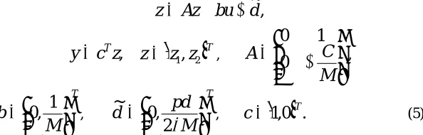
The state space representation of the aforementioned system is as follows:
,
~
d
bu
Az
z
,
z
c
y
Tz
z
1,
z
2
T,
M
C
A
0
1
0
,
T
M
b
0
,
1
,T
M
pd
d
2
,
0
~
,
c
1
,
0
T.
(5)where the state
z
1represents the position of the feed drive system which can be measured by using a linear encoder.
Td d
d~ ~1,~2 is assumed to be matched (i.e., it lies in the space range of the input matrix b).
Assumptions for Controller Design
The following items are assumed for the controller design in this study. 1) The nominal parameters of M and C in (5) are known. 2) Position
z
1
x
and velocityz
2
x
are measurable. 3) d is unknown and bounded.4) The reference signals for z1 and z2, namely, z1ref and z2ref , are given Nonlinear Sliding Surface and Its Stability
This section considers the design of sliding-mode controller with an NLSS for ball-screw feed-drive systems. Using an NLSS, the damping ratio of the system can be changed from its initial low value to a final high value. The initial low value of the damping ratio results in a quick response, and the later high damping avoids overshoot to reduce the energy consumption. The proposed nonlinear sliding surface achieves high performance and robustness unlike a sliding surface designed by minimizing a quadratic index, which normally lead to a linear sliding surface. The NLSS consists of a linear term and nonlinear term. The linear term comprises a gain matrix that has a very low damping ratio, thereby facilitating a fast response. The nonlinear term is introduced to change the damping ratio of the system. Based on the system dynamics in (5), NLSS is proposed as :
F
P
1
e
,
S
,
]
,
[
e
1e
2 Tz
z
refe
z
ref
[
z
1ref,
z
2ref]
T (6)Here, e is the tracking error vector of the feed-drive system. zref is the desired trajectory vector. P is a positive constant
to adjust the damping ratio. F is the linear term of the sliding surface. Ψ is a nonpositive nonlinear function that depends on the output and desired velocity, which is used to change the system’s closed loop damping ratio. The nonlinear function should have the following two properties:
It should change from 0 to (–β), as the output approaches the setpoint from its initial value, where β> 0.
One possible choice of Ψ which respects the above properties is as follows:
exp(
(
1
))
exp(
1
)
)
1
exp(
1
2
(7)where β is used as a tuning parameter. This parameter contributes to decide the final damping ratio along with the
matrix P. It should be noted that the choice of Ψ is not unique and any function with the above mentioned properties
can be used. ζ is the damping ratio which indicate how much the system output changes with respect to the desired reference. ζ= (z1-z1o)/(z1ref –z1o), where z1o is the initial position. Here we have generalized this function ζ= (z1(i)-z1 (i-1))/(z1ref(i)-z1(i-1)) with ias the sampling instant. When the system output reaches the desired reference, ζ=1 and Ψ = -β
which results in an increase of damping ratio to avoid the overshoot. If the system output is far from the desired
reference, then Ψ becomes very small which provide small damping ratio to make the system response fast. Stability of Sliding Surface: During the sliding mode S=0, we have
1 1
(
F
P
)
e
e
(8)In order to show the stability of the proposed sliding dynamics, consider a Lyapunov function candidate for the system in (8) as follows:
1 12
2
1
e
V
(9) Using (8), the time derivative of the Lyapunov function candidate becomes2 1 1
(
F
P
)
e
V
(10)Since Ψ≤0, F>0, and P>0,we have
V
1
0
(11) which ensures the system stability during ideal sliding mode.Controller Design
This section design a controller to enforces the system (5) to move from any initial conditions to the sliding surface and thereafter to remain on it. Assuming the reference position, velocity, and acceleration are given and considering the feed-drive dynamics, the following controller is designed as:
,
)
sgn(
}
{
2
Pe
dt
d
S
Q
KS
Az
z
M
u
ref
[
F
P
,
1
]
(12)where K is the controller gain. sgn(S) represents the sign function of the sliding surface and Q is chosen from the maximum bond of uncertainity as follows:
)
~
max(
d
2Q
(13)For asymptotic stability and to force the system to desired sliding surface, the time derivative of the following Lyapunov function must be negative:
2
2
1
S
V
(14) The time derivative of the Lyapunov function candidate is
Pe
1dt
d
e
S
Using system (5), the tracking error dynamics is
e
z
ref
Az
bu
d
~
(16) Substituting (16) into (15) leads to
{
~
}
Pe
1dt
d
d
bu
Az
z
S
V
ref
(17) Using control law (12),it can be seen that
V
S
KS
Q
sgn(
s
)
d
~
2
(18) Thus, with (13), it is easy to show that
V
0
(19)Chattering Elimination
The major inconvenient of SMC is the existence of chattering phenomenon. Chattering can cause low control accuracy, high wear of moving mechanical parts, or might even damage the system being controlled. As it is undesirable, since it involves extremely high control activity, and furthermore may excite high-frequency dynamics neglected in the course of modelling. Hence it must be eliminated for the controller to perform properly. So in order to solve this problem , approximate (smoothed) implementations of sliding mode control techniques have been suggested where the discontinuous “sign” term is replaced by a continuous smooth approximation. Here, we use a saturation function in place of signum function in the implementation of control law, to smoothen the input control signal (u). The saturation function which can be defined as:
s
s
s
s
s
sat
,
1
,
,
1
)
,
(
(20)where ε is a positive constant that defines the thickness of the boundary layer. The presence of this boundary layer is required to completely eliminate chattering phenomenon. Hence it can be concluded that chattering is a feature of discontinuous control, and replacement of this discontinuous control with a continuous would result in chattering elimination.
III. RESULT AND DISCUSSION
Simulation model of the ball screw feed-drive system (5) is performed using MATLAB for the desired position as 0.5. The system dynamics can be represented by the following second-order system:
M
pd
u
M
x
x
M
C
x
x
2
0
1
0
0
1
0
2 1 2 1
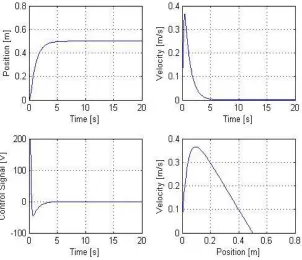
(21)Fig. 2. Responses without disturbances
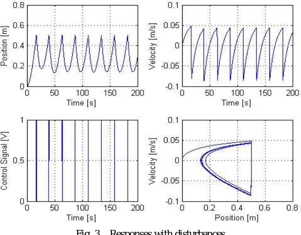
In the Fig.3.,it shows the closed loop responses of the system with disturbances of position, velocity and control signal using ON/OFF controller. Whenever it attains position 0.5 it get a control signal and due to the disturbances the position changes and the control signal become off .
Fig. 3. Responses with disturbances
In the case of ON/OFF controller the system was not achieving its desired position. So inorder to ensure the robust performance SMC is used. The SMC controller with an NLSS (12) and the controller with an LSS [i.e., Ψ=0 ] are
Fig.4. Controller with LSS
In the Fig.4., it shows the output response of the controller with LSS. The system settles at about 3s and the system response is slow and control input chattering occurred is more.
In the Fig.5, it shows the output response of the controller with LSS and NLSS respectively. The plot clearly shows that with NLSS performance improves significantly. Furthermore, it shows very clearly that settling time can be minimized with NLSS. With the proposed NLSS output settles in 3s without any overshoot.
To demonstrate the ability of the proposed approach to reduce the control input variance, we compute the control input variance as follows:
N
u
Ni i
12 2
)
(
(22)where ui denotes the control input value at the ith sampling instant, N is the total number of sampling instants (i =
1,…,N), and μ is the mean of all the control input values. The proposed approach provided a control input variance that was about 0.6% smaller than LSS. It should be noted that elimination of control input chattering was also considered in this study. In order to smoothen the input control signal, we use saturation function in place of signum function in the implementation of control law. Fig. 6 and Fig.7 shows the controller with LSS and NLSS by using saturation function respectively. Also computed the control input variance with the same formulae(22), here also the proposed approach provide a control input variance that was about 0.1% smaller than LSS.
The controller parameters used are given in Table II.
TABLE II
CONTROLLER PARAMETER VALUES Parameter K
s-1
F s-1
P s-1
β
-
Q ms-2 LSS
NLSS
80 80
1 1
1 1
- 1
0.3 0.3
In the Fig.6, it shows the controller with LSS using saturation function. The control input chattering of LSS is eliminated.
In the Fig.7., it shows the controller with NLSS using saturation function. Here also it is clear that control input chattering is eliminated in the control signal vs time plot.
Fig. 7. Controller with NLSS avoids chattering
From simulation results it is clear that the consumed energy and control input variance are reduced significantly with respect to conventional LSS and also chattering is eliminated from the control input, by changing the system damping ratio from its initial low value to its final high value.
IV. CONCLUSION
A sliding-mode controller with NLSS has been proposed for ball-screw feed-drive systems. The main advantage of the proposed NLSS varies according to the output so that the damping ratio of the system changes from its initial low value to its final high value as the output changes from its initial value to the reference point. From the simulation results, it can be observed that a significant reduction in settling time without overshoot and control input variance can be achieved with the proposed surface. Chattering avoidance in the control input was also considered by using saturation function. Future work includes optimal selection of NLSS.
REFERENCES
[1] Utkin, V.I.“Variable structure systems with sliding modes,” IEEE Trans. Autom.control,vol.22, pp.212-222 ,1977.
[2] J.Y Hung, W.Gao, And J.C. Hung, “Variable structure control: A survey,” IEEE Trans. Ind. Electron., vol.59, no. 8,pp. 3189-3198, Aug.2012. [3] Y. Altintas, K. Erkorkmaz, and W.-H. Zhu, “Sliding mode controller design for high speed feed drives,” ClRP Ann., vol. 49, no. 1, pp. 265–270, 2000. [4] C. L. Chen, M. J. Jang, and K. C. Lin, “Modeling and high-precision control of a ball-screw-driven stage,” Precision Eng., vol. 28, no. 4, pp. 483–495, Oct. 2004. [5] P. Braembussche, J. Swevers, and H. Brussel, “Design and experimental validation of robust controllers for machine tool drives with linear motor,” Mechatronics,
vol. 11, no. 5, pp. 545–562, Aug. 2001.
[6] A. Rojko and K. Jezernik, “Sliding-mode motion controller with adaptive fuzzy disturbance estimation,” IEEE Trans. Ind. Electron., vol. 51, no. 5, pp. 963–971, Oct. 2004.
[7] L. Yew-Wen, T. Li-Wei, and L. Li-Gang, “Study of reliable control via an integral-type sliding mode control scheme,” IEEE Trans. Ind. Electron., vol. 59, no. 8, pp. 3062–3068, Aug. 2012.
[8] H.-T. Yau and J.-J. Yan, “Adaptive sliding mode control of a highprecision ball-screw-driven stage,” Nonl. Anal. Real World Appl., vol. 10, no. 3, pp. 1480–1489, Jun. 2009.