Performance Evaluation of UPQC for Power
Quality Improvement using PQ Theory
N.C.Kotaiah1,Dr.K.Chandra Sekhar2
Associate Professor, Dept. of Electrical & Electronics Engineering, R.V.R & J.C.College of Engineering, Chowdavaram, Guntur, A.P, India.1
Professor, Dept. of Electrical & Electronics Engineering, R.V.R & J.C.College of Engineering, Chowdavaram, Guntur, A.P, India.2
ABSTRACT: Voltage sensitive electronic equipment, such as computers, process controllers, programmable logic controllers, adjustable speed drives and robotic devices is increasingly used in modern industrial processes. Power quality disturbances are usually caused by load switching, system faults, motor starting, load variations, nonlinear loads, and intermittent loads and arc furnaces.Industrial loads thus require a supply free of many electrical disturbances like surge, dip, harmonic distortions, interruptions, flicker and signaling voltages.. The effect of these disturbances is as bad as complete shutdown of a production line, hence giving rise to the growing interest and need for mitigation of such power quality problems. Flexible ac transmission system devices are mainly intended to enhance the power quality of the system. Every device has its own advantages and drawbacks, but out of all devices, UPQC is the most preferable device for the researchers, because it eliminates all the power quality related problems efficiently. Most of the distributed generations from renewable energy sources are associated to the grid through power electronic interface, which set up added harmonics in the distribution systems. Research is being conceded to incorporate active filtering that is the grouping of series APF and shunt APF coupled back to back on the dc side and distribute a common dc-link capacitor with precise interface such that a regular power quality (PQ) platform could be achieved. For comprehensive solution, a unified power quality conditioner (UPQC) could be the main widespread PQ protecting device for sensitive non-linear and unbalanced loads, which necessitate quality input supply. Also, load current harmonic isolation requests to be ensured for maintaining the eminence of the supply current. The present paper describes a re-evaluate the UPQC for enhancing power quality using PQ theory under various loading conditions. Based on voltage compensation scheme, the control proposal has been intended. As a result, power can be transferred from one feeder to nearby feeders to reimburse for sag/swell and interruption. The presentation of the UPQC as well as the implemented PQ control algorithm is demonstrated by simulation. The results acquired in MATLAB on feeder system illustrate the efficacy of the proposed configuration.
KEYWORDS: unified power quality conditioner (UPQC), PI controller, Active power filter (APF), harmonic compensation, power quality, reactive power compensation.
I.INTRODUCTION
The basic applications of FACTS-devices are voltage control, reactive power compensation, and stability perfection, power conditioning, flicker alleviation, power flow control, amplification of transmission capability, power quality advancement and interconnection of renewable and distributed generation and storages.
Figure 1 shows the fundamental idea of FACTS for transmission systems. The tradition of lines for active power transmission should be preferably up to the thermal limits. Voltage and stability limits shall be altered with the means of the numerous different FACTS devices. It can be seen that with rising line length, the chance for FACTS devices gets more and more imperative. The authority of FACTS-devices is attained through switched or controlled shunt compensation, series compensation or phase shift control. The devices work electrically as quick current, voltage or impedance controllers. The power electronic devices permit very diminutive reaction times down to far below one second.
Fig 1. Limit conditions of transmissions lines for diverse voltage levels
II.UPQC TOPOLOGY AND CONTROL STRATEGY
Unified power quality conditioner (UPQC) happens to be the majority widespread power conditioning equipment that can ease both voltage and current quality problems [3, 4]. By using a unified power quality conditioner (UPQC) [5]– [6], it is likely to certify a regulated voltage for the loads, balanced and with little harmonic distortion. Though the UPQC ditches undistorted currents from the efficacy grid, the grid voltage and the load current have harmonic inside. The UPQC consists of two dynamic filters, the series active filter (SAF) and the shunt or parallel active filter (PAF) [5], [7].
The PAF is regularly controlled as a non sinusoidal current source, which is answerable for compensating the harmonic current of the load, whereas the SAF is controlled as a non sinusoidal voltage source, which is accountable for compensating the grid voltage. But its consequent control gives it incomparable attribute in terms of collective responsibility and condensed VA rating as compared to entity dynamic voltage restorer (DVR) [8],[10] or active power filter (APF) [6],[9],[10]. A UPQC consists of voltage source inverters connected in cascade.
offers harmonic separation to the utility. SE may also allocate some VAR depending upon the control, expressed advance in the consequent section.
A. Shunt Controller for UPQC:
Shunt controller theory was initially proposed by Akagi. This theory is based on the transformation of three
phase quantities to two phase quantities in α-β frame and the calculation of instantaneous active and reactive power in
this frame. A basic block diagram of this theory is shown in fig.3. Sensed inputs , , , , are
fed to the controller, and these quantities are processed to generate reference current commands (∗ , ∗ , ∗ ), which
are fed to a pulse width modulation (PWM) signal generator to generate final switching signals to the converters of UPQC; therefore this block works as controller for UPQC.
The system terminal voltages are given as
= sin ( ) = sin ( −2 /3)
= sin ( −4 /3) (1)
Fig, 2. Block diagram of the proposed UPQC topology.
V
I
V
I
P
Q
and the respective load currents are given as
= { ( )− }
= { ( −2 /3)− }
=∑ { ( −2 /3)− } (2)
In a-b-c coordinates, a, b, and c axes are fixed on the same plane, and are electrically displaced each other by 2π/3.
The instantaneous space vectors va and iLa are set on the “a” axis, and their amplitude varies in positive and negative directions with time. This is true for the other two phases also. These phasors can be transformed into α–β coordinates using Park’s transformation as follows:
= 1 −1 2⁄ −1 2⁄
0 √3 2⁄ − √3 2⁄ (3)
= 1 −1 2⁄ −1 2⁄
0 √3 2⁄ − √3 2⁄ (4)
Where α and β axes are the orthogonal coordinates. Conventional instantaneous power for three-phase circuit can be defined as
= + (5) Where p is equal to conventional equation
= + + (6)
Similarly, the IRP is defined as
=− + (7)
Therefore, in matrix form, instantaneous real and reactive power are given as
= − (8)
The α-β currents can be obtained as
=
∆ − (9)
Where
∆= + (10)
Instantaneous active and reactive powers and can be decomposed into an average (dc) and an oscillatory component.
= ̅+
= + (11)
Where ̅ and are the average (dc) part and and are the oscillatory (ac) part of these real and reactive instantaneous powers. Reference source currents are calculated to compensate the reactive power and the oscillatory component of the instantaneous active power. Therefore, the reference source currents ∗ and ∗ in α-β coordinate are expressed as
∗
∗ =∆
− ̅
0 (12) Theses currents can be transformed in a-b-c quantities to find the reference currents in a-b-c coordinates using inverse transformation. ∗ ∗ ∗ =
1⁄√2 1 0 1⁄√2 −1 2⁄ √3 2⁄ 1⁄√2 −1 2⁄ − √3 2⁄
∗
∗
∗ (13)
Where ∗ is the zero sequence components, which is zero in three- phase three wire system.
Fig .4. Generation of Gating pulses.
B. Series Controller for UPQC:
Fig 5. Block Diagram of series Controlled UPQC
Series controller equations:
= ⎣ ⎢ ⎢ ⎢ ⎡1
0 √ √
√ √ √ ⎦
⎥ ⎥ ⎥ ⎤
− (14)
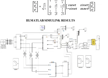
III.MATLAB/SIMULINK RESULTS
Fig.7. Source currents of the series connected VSC.
Fig VSC.8 Source Voltage, Source Current and Load Current of the Series Connected.
Figure.6. Shows the MATLAB/SIMULINK model of the series connected VSC. Figure.7.shows the Source currents of the series connected VSC. Current transients are observed between time 0.25 sec to 0.35 sec. Figure.8.shows the source voltage, source current and load current of the series connected VSC. The response change can be observed from time 0.25 to 0.35 sec.
Fig .10. Load current of the series connected VSC.
Fig.11. Source Voltage, DVR Voltage and Load Voltage of the Series Connected VSC.
Fig 12.MATLAB/SIMULINK Circuit of the Shunt Connected VSC.
Fig.13. Source Voltage, Source Current and Load Current of the Shunt Connected VSC.
Fig.14. Source current of the shunt connected VSC.
Fig.15. Power factor of the shunt connected VSC.
Fig 17. Source Voltage, DVR Voltage and Load Voltage of the Shunt Connected VSC.
Figure 15 show the power factor of the shunt connected VSC Figure.16.shows the Load current of the shunt connected VSC. Figure 17 shows the source voltage, induced voltages from the compensator and load voltages. Since the source parameters are varied during 0 to 0.04 sec time, the compensating parameters are also induced during the same period to compensate the source parameters.
Fig.18. MATLAB/SIMULINK circuit of the both series and shunt connected VSC.
Fig 19. Source Voltage, Source Current and Load Current of the both Series and Shunt Connected VSC.
Fig .20. Source current of the both series and shunt connected VSC.
Figure.19. shows the source voltage, source current and load current of the both series and shunt connected VSC. Figure 20 shows the Source current of the both series and shunt connected VSC.
Fig .22. Load current of the both series and shunt connected VSC.
Fig .23. Source voltage, injected voltage and load voltage of the both series and shunt connected VSC. Figure 21 shows the Power factor of the both series and shunt connected VSC. Figure.22.shows the load current of the both series and shunt connected VSC. Figure 23 shows the source voltage, injected voltage and load voltage of the both series and shunt connected VSC. Source parameters are varied during 0.25 to 0.35 sec time and thus the compensator also induces compensating parameters during the same period of time, compensating the source parameters.
IV.CONCLUSION
In this paper, the p-q control scheme for the shunt converter of UPQC is proposed which has the capability to compensate voltage sags and current harmonics in the distribution system. The simulations are carried out with series, shunt and both series and shunt connected VSC and the results are presented. This simulation study shows that the source current with UPQC maintains sinusoidal without harmonics. The proposed UPQC also mitigates the effects of voltage sag and swells.
REFERENCES
[1] M. Bollen, “Understanding Power Quality Problems. Piscataway,” NJ, USA: IEEE, 2000, ch. 1, pp. 1–35.
[2] H. Fujita and H. Akagi, “Voltage-regulation performance of a shunt active filter intended for installation on a power distribution system,”
IEEE Trans. Power Electron., vol. 22, no. 3, pp. 1046–1053, May 2007.
[3] K.Kowalenko, Distributed Power Offers an Alternative to Electric Utilities, vol. 25, IEEE Press, Piscataway, NJ, 2001.
[4] F. Blaabjerg, Z. Chen, S.B. Kjaer, Power electronics as efficient interface in dispersed power generation systems, IEEE Trans. Power Electron. 19 (September (5)) (2004) 1184–1194.
[5] M. Aredes, K. Heumann, and E. Watanabe, “An universal active power line conditioner,” IEEE Trans. Power Del., vol. 13, no. 2, pp. 545–551, Apr. 1998.
[7] H. Fujita and H. Akagi, “The unified power quality conditioner: The integration of series and shunt-active filters,” IEEE Trans. Power Electron., vol. 13, no. 2, pp. 315–322, Mar. 1998.
[8] F.Z. Peng, Editorial: “Special issue on distributed power generation,” IEEE Trans. Power Electron. 19 (September (5)) (2004) 1157– 1158.
[9] T.S. Perry, “Deregulation may give a boost to renewable resources,” IEEE Spectr. (January) (2001) 87.
[10] H. Fujita, H. Akagi, “The unified power quality conditioner: the integration of series and shunt active filters”, IEEE Trans. Power Electron. 13 (March (2)) (1998) 315–322.
[11] M. Kalyanasundaram, Merin P. George, S.Suresh Kumar “Unified power quality conditioner (UPQC) for the mitigations of power quality
problems in distribution system,”IJEAT ISSN: 2249 – 8958, Volume-2, Issue-4, April 2013.
[12] Haibo LIU, Chengxiong Mao, Jiming LU ,Dan Wang Double-source alternate backup type unified power quality conditioner, Journal of