NDA-24213 ISSUE 3 STOCK # 151947
CallCenterWorX
System Manual
LIABILITY DISCLAIMER
NEC America, Inc. reserves the right to change the specifications, functions, or features, at any time, without notice.
NEC America, Inc. has prepared this document for use by its employees and customers. The information contained herein is the property of NEC America, Inc. and shall not be reproduced without prior written approval from NEC America, Inc.
NEAX, Dterm, CallCenterWorX, and QueWorX are registered trademarks of NEC Corporation. MS-DOS and Microsoft are registered trademarks of Microsoft Corporation. Microsoft Windows 95, Windows 98, and Windows NT are trademarks of Microsoft Corporation. 3Com is a registered trademark of 3Com Corporation. Adobe Acrobat Reader, PDF, and the Acrobat logo are a registered trademarks of Adobe Systems Incorporated. Spectrum is a registered trademark of Spectrum Corporation. Rainbow Sentinel Driver is a registered trademark of Rainbow Technologies, Inc.
Copyright 2000
NEC America, Inc.
Printed in the U.S.A
NDA-24213 ISSUE 3 MARCH 2000
NEAX2000 IVS
CallCenterWorX System Manual
TABLE OF CONTENTS
Page
NDA-24213 TABLE OF CONTENTS
Page i
Overview
CHAPTER 1 CallCenterWorX Overview ... 3
1. General Description ... 3
2. CallCenterWorX ACD 2.0 Features and Enhancements ... 4
3. CallCenterWorX MIS 2.0 Features and Enhancements ... 5
4. System Capacities ... 6
5. Other Documentation ... 7
Installation and Configuration
CHAPTER 2 System Requirements ...111. Variations in Setup ...11
2. ACD Computer (Client or Server) With and Without MIS ... 12
3. ACD Computer with MIS Using Remote MIS PC via TCP/IP ... 13
4. ACD Computer with MIS Using Remote MIS PC via RS-232 Serial Connection ... 14
5. Remote MIS PC Using TCP/IP ... 15
6. Remote MIS PC Using RS-232 ... 16
7. CallCenterWorX MIS PC Support ... 17
7.1 Multiple MIS PCs ... 17
7.2 IP Connections ... 17
8. Multi-tenant MIS Considerations—Split Numbering ... 18
CHAPTER 3 Connection Drawings ... 19
1. Installing the PN-CC00 and the PN-AP01 ... 19
1.1 Crossover Reverse Pin-out ... 19
2. Installing the PN-CC01 and the PN-AP01 ... 20
3. PN-CC00 Connecting Through a Hub ... 21
3.1 Straight-Through Pin-out ... 21
4. PN-CC01 Connecting Through a Hub ... 22
5. PN-CC00 Connection for ACD Computer to Remote MIS PC Serially ... 23
6. PN-CC01 Connection for ACD Computer to Remote MIS PC Serially ... 24
7. Connecting Wall Display Boards ... 25
CHAPTER 4 Programming the PBX and the Dterm ... 27
1. AP01 Initialization ... 27
TABLE OF CONTENTS (CONTINUED)
Page
TABLE OF CONTENTS NDA-24213
Page ii
3. Programming ACD/OAI Operation Codes ... 30
4. Programming Dterm Key Assignment ...31
5. Programming ACD Group Announcements ... 32
6. Sending of Returned Result and SMFN ... 34
7. Programming the Dterm Series E ACD Terminal ... 35
7.1 Programming the Keys ...35
7.2 Service Conditions ... 36
8. Programming the Dterm Series III ACD Terminal ... 37
8.1 Programming the Keys ...37
8.2 Service Conditions ... 38
CHAPTER 5 Configuration Procedures ... 39
1. Configuring the ACD Computers ... 41
1.1 ACD Computer (Client or Server) With or Without MIS ... 41
1.2 ACD Computer Setup for Use with Remote MIS PC via TCP/IP ... 43
1.3 ACD Computer Setup for Use with Remote MIS PC via RS-232 ... 45
2. Configuring the MIS PCs ... 47
2.1 MIS PC Setup for Use via TCP/IP ... 47
2.2 MIS PC Setup for Use via RS-232 ... 49
CHAPTER 6 Installation ... 51
1. Security Key Installation Instructions ... 51
2. Installation Information Needed ... 52
2.1 ACD Installation Option ...52
2.2 IP Address or Host Name ... 52
2.3 Location of Installed Program ... 52
3. CallCenterWorX CD-ROM Installation Instructions ...53
3.1 Installation Setup ... 53
3.2 MAT Client Installation Option ... 61
3.3 Server and MAT Client Installation Option ... 64
3.4 MIS Installation Option ... 70
4. Starting CallCenterWorX ACD ... 77
Menu Commands
CHAPTER 7 ACD Menu Commands ...811. File Menu ...82
2. Server Menu ... 82
3. View Menu ... 83
4. Options Menu ... 86
5. MAT Menu ... 87
5.1 Menu Commands ... 87
TABLE OF CONTENTS (CONTINUED)
Page
NDA-24213 TABLE OF CONTENTS
Page iii
5.2.1 How to Use the Buttons... 88
5.3 Information Choices ... 89
5.4 Message Bars ... 89
6. Report Menu ... 90
7. Window Menu ... 93
8. Help Menu ... 93
CHAPTER 8 MIS Menu Commands ... 95
1. File Menu ... 95
2. Edit Menu ... 96
3. Administration Menu ... 97
4. Configuration Menu ... 98
4.1 System Parameters ... 99
4.2 Modifying Delay Intervals ... 99
4.3 Configuring Communication Type ... 100
4.4 Agent Assignments ... 102
4.5 Agent Group Assignments ... 104
4.6 Break Type Assignments ... 105
4.7 Pilot Assignment ... 106
4.8 Position Assignments ... 107
4.9 Split Assignments ... 108
4.10 Tally Code Assignments ...110
4.11 System Name Assignment ... 111
4.12 Trunk Assignments ...112
4.13 Wallboard Message Sets ...113
4.14 Constructing Message Sets ...115
4.15 Scheduling Message Sets ...116
4.16 View Database Limits ...117
5. Status Screens Menu ...118
5.1 Split Status ...119
5.1.1 Daily Statistics ... 121
5.1.2 Hourly Statistics... 122
5.1.3 Agent Summary Statistics ... 123
5.1.4 Agent Detail Statistics ... 124
5.1.5 Queue Statistics ... 125
5.1.5.1 Standard and High Priority Queues ... 125
5.1.5.2 Agent Personal Queue... 126
5.2 System Status ... 127
5.2.1 Daily Statistics ... 128
5.2.2 Hourly Statistics... 129
5.2.3 Agent Summary Statistics ... 130
5.2.4 Split Detail Statistics... 131
TABLE OF CONTENTS (CONTINUED)
Page
TABLE OF CONTENTS NDA-24213
Page iv
5.3 Modify Intervals ... 134
6. Reports Menu ... 135
6.1 Agent Reports ... 136
6.1.1 Agent Summary Report ... 137
6.1.2 Agent ACD Detail Report ... 138
6.1.3 Agent PBX Detail Report ... 139
6.1.4 Agent Staffing Report... 140
6.1.5 Agent Break Report ... 141
6.2 Agent Group Reports ... 142
6.3 Split Reports ... 144
6.3.1 Split Summary Report...145
6.3.2 Split Traffic Report ... 146
6.3.3 Split Profile Report ... 147
6.3.4 Split Staffing Report ... 148
6.3.5 Split Break Report... 150
6.3.6 Split Answer Delay Report ... 151
6.3.7 Split Abandon Delay Report ... 152
6.4 Pilot Reports ... 153
6.5 Trunk Group Reports ... 155
6.5.1 Trunk Group Call Volume Report... 156
6.5.2 Trunk Group Answer Delay Report ... 157
6.5.3 Trunk Group Abandon Delay Report ... 158
6.5.4 Trunk Group Trunk Circuit Report... 159
6.6 Tally Code Reports ... 160
6.6.1 Tally Code Summary Report by Split ... 161
6.6.2 Tally Code Summary Report by Pilot ... 162
6.7 Report Scheduler ... 163
7. View Menu ... 164
8. Help Menu ... 165
Procedures
CHAPTER 9 ACD Procedures ... 1691. Method of Programming ... 169
1.1 Entering Data ... 169
2. Order of programming ... 170
3. Tenant Data ... 171
4. Split Data ...173
5. Logon Data ... 178
6. Position Data ... 182
7. Call Control Vectors ... 184
TABLE OF CONTENTS (CONTINUED)
Page
NDA-24213 TABLE OF CONTENTS
Page v
9. Trunk Group Data ... 189
10. IVR Data ... 191
11. Week Schedules ... 192
12. Holiday Schedules ... 194
13. Holiday Calendar ... 196
14. System Data ... 198
14.1 User Settings ... 198
14.2 Time Out Settings ... 202
15. Communication Data ... 203
16. Backup Database ... 205
17. Trace Settings ... 208
CHAPTER 10 MIS Procedures ... 209
1. CallCenterWorX MIS Initial Setup ... 209
2. Configuring the MIS ... 214
2.1 ACD configuration data ... 214
2.2 Local configuration data ... 214
2.3 Assigned Names ... 214
3. Naming Entities ... 215
4. Agent Procedures ... 216
4.1 Adding an Agent ... 216
4.2 Changing an Agent Name ... 217
4.3 Deleting an Agent ... 217
5. Agent Group Name Assignment ... 218
6. Pilot Assignment ... 219
7. Position Assignment ... 220
8. Tally Code Assignment ... 221
9. System Name Assignment ... 222
10. Trunk Group Name Assignments ... 223
11. Wall Display Board Assignments ... 224
11.1 Assigning Message Sets ... 224
11.2 Scheduling Message Sets ... 227
12. Reports ... 228
12.1 Major Categories ... 228
12.2 Minor Categories ... 229
12.3 Generating a Report ... 230
12.3.1 Selecting the Subject... 230
12.3.2 Formatting a Report ... 233
12.4 Scheduling and Printing a Report ... 234
12.5 Weekend Suppression of Printing ... 237
12.6 Generating a Graph from a Report ... 238
12.7 Selecting a Type of Graph ... 238
TABLE OF CONTENTS (CONTINUED)
Page
TABLE OF CONTENTS NDA-24213
Page vi
12.8.1 Line graph ... 239
12.8.2 Line Only graph ... 239
12.8.3 Step graph ... 239
12.8.4 Step Line Only graph ...239
12.8.5 Vertical Bar graph ... 239
12.8.6 Horizontal Bar graph ... 240
12.8.7 Extended Vertical Bar graph ... 240
12.8.8 Extended Horizontal Bar graph ... 240
12.8.9 Stacked Vertical Bar graph ... 240
12.8.10 Stacked Horizontal Bar graph ...241
12.8.11 Manhattan graph ...241
12.8.12 RoofTop graph ... 241
12.8.13 Ribbon graph ... 241
12.8.14 Pie graph ... 242
12.8.15 Isographic Pie graph ... 242
12.8.16 Area graph ... 242
12.8.17 Strata graph ... 242
12.8.18 Strata Vertical Bar graph ... 243
12.8.19 Strata Horizontal Bar graph ... 243
Reference
CHAPTER 11 CallCenterWorX Online Help ... 2471. Online Help Features ...247
2. Accessing the Online Help System ... 247
3. Navigating the Help System ... 248
3.1 Contents Tab ... 248
3.2 Index Tab ... 249
3.3 Find Tab ... 250
4. Printing Help Topics ... 251
4.1 Printing from the Contents, Index or Find Tabs ... 251
5. Tips ... 251
CHAPTER 12 MIS Statistical Definitions and Methods ... 253
CHAPTER 13 MIS Error Messages ... 257
LIST OF FIGURES
Figure Title Page
NDA-24213 LIST OF FIGURES
Page vii
Figure 3-1 PN-CC00 Connection through 10 Base T Transceiver ... 19
Figure 3-2 Crossover Reverse Pin-out ... 19
Figure 3-3 PN-CC01 Connection Straight to ACD Computer (Client or Server) ... 20
Figure 3-4 PN-CC00 Connecting Through a Hub ... 21
Figure 3-5 Straight-Through Pin-out ... 21
Figure 3-6 PN-CC01 Connecting Through a Hub ... 22
Figure 3-7 PN-CC00 with RS-232 Serial Connection ... 23
Figure 3-8 PN-CC01 Connection for ACD Computer to Remote MIS PC Serially ... 24
Figure 3-9 PN-CC00 Connecting ACD Computer or MIS PC to Wall Boards ... 25
Figure 3-10 PN-CC01 Connecting ACD Computer or MIS PC to Wall Boards ... 26
Figure 3-11 Connection of RS-232 to COM Port ... 26
Figure 4-1 Dterm Series E ACD Terminal ... 35
Figure 4-2 Dterm Series III ACD Terminal ... 37
Figure 5-1 Configuration Options ... 39
Figure 5-2 ACD Computer (Client or Server) With or Without MIS ... 40
Figure 5-3 ACD Computer Setup for Use with Remote MIS PC via TCP/IP ... 42
Figure 5-4 ACD Computer Setup for Use with Remote MIS PC via RS-232 ... 44
Figure 5-5 MIS PC Setup for Use via TCP/IP ... 46
Figure 5-6 MIS PC Setup for Use via RS-232 ... 48
Figure 6-1 Security Key ... 51
Figure 6-2 Connecting the Security Key ... 52
Figure 6-3 Installation Introduction ... 54
Figure 6-4 Contact NEC America ... 54
Figure 6-5 Documentation ... 55
Figure 6-6 Install Selection ... 56
Figure 6-7 Welcome - ACD ... 56
Figure 6-8 License Agreement - ACD ... 57
Figure 6-9 User Information - ACD ... 58
Figure 6-10 Choose Destination Location - ACD ... 59
Figure 6-11 Setup Type Selection - MAT Client ... 60
Figure 6-12 Select Program Folder - MAT Client ... 61
Figure 6-13 Copying Files - MAT Client ... 62
Figure 6-14 Add Folder Icon - MAT Client ... 62
Figure 6-15 Setup FInish - MAT Client ... 63
Figure 6-16 Setup Type Selection - Server and MAT Client ... 64
Figure 6-17 IP Address Configuration - Server and MAT Client ... 65
Figure 6-18 Select Program Folder - Server and MAT Client ... 66
Figure 6-19 Copying Files - Server and MAT Client ... 67
LIST OF FIGURES (CONTINUED)
Figure Title Page
LIST OF FIGURES NDA-24213
Page viii
Figure 6-21 Setup Finish - Server and MAT Client ... 69
Figure 6-22 Welcome - MIS ... 70
Figure 6-23 License Agreement - MIS ... 71
Figure 6-24 User Information - MIS ... 72
Figure 6-25 Choose Destination Location - MIS ... 73
Figure 6-26 Select Program Folder - MIS ... 74
Figure 6-27 Copying Files - MIS ... 75
Figure 6-28 Setup Finish - MIS ... 76
Figure 6-29 Starting CallCenterWorX ACD ... 77
Figure 6-30 CallCenterWorX ACD Console ... 78
Figure 7-1 CallCenterWorX ACD Console Screen ... 81
Figure 7-2 ACD Server Connection ... 82
Figure 7-3 Server Name Dialog ... 82
Figure 7-4 Console Screen ... 83
Figure 7-5 Toolbars Options ... 84
Figure 7-6 New Toolbar Window ... 84
Figure 7-7 Data Entry Screen Background Colors ... 86
Figure 7-8 MAT Toolbar Icons ... 87
Figure 7-9 MAT Menu ... 87
Figure 7-10 Sample Data Entry Screen ... 88
Figure 7-11 Report Menu ... 90
Figure 7-12 Sample Data Entry and Data Report Screens ... 91
Figure 7-13 Sample Report Print Preview Screen ... 92
Figure 8-1 File Menu ... 95
Figure 8-2 Edit Menu Commands ... 96
Figure 8-3 Add Record and Delete Record Icons ... 96
Figure 8-4 Graph View and Text View Icons ... 96
Figure 8-5 Refresh Report and Create Graph Icons ... 96
Figure 8-6 Modify Graph and Zoom Out Icons ... 96
Figure 8-7 Change Password Dialog ... 97
Figure 8-8 Disk Space Usage Screen ... 97
Figure 8-9 Configuration Menu Screen ... 98
Figure 8-10 Modify Delay Intervals Window ... 99
Figure 8-11 Change System Parameters Window – RS-232 ... 100
Figure 8-12 Change Systems Parameters Window – TCP/IP ... 101
Figure 8-13 Agent Assignment Window ... 102
Figure 8-14 Edit Add Record Selection ... 103
Figure 8-15 Add Agent Record Window ... 103
Figure 8-16 Agent Group Name Assignments Window ... 104
Figure 8-17 Break Type Assignment Window ... 105
Figure 8-18 Pilot Assignment Screen ... 106
LIST OF FIGURES (CONTINUED)
Figure Title Page
NDA-24213 LIST OF FIGURES
Page ix
Figure 8-20 Split Assignment Window ... 109
Figure 8-21 Tally Name Assignment Window ... 110
Figure 8-22 System Name Assignment Window ... 111
Figure 8-23 Trunk Allocation Window ... 112
Figure 8-24 Select Wallboard Message Sets ... 114
Figure 8-25 Message Set Name Assignment Dialog ... 114
Figure 8-26 Message Sets Assignment Screen ... 115
Figure 8-27 Schedule Wallboard Message Sets ... 116
Figure 8-28 Database Limits Screen ... 117
Figure 8-29 Status Screens Menu ... 118
Figure 8-30 Split Status Screen Menu ... 119
Figure 8-31 All Split Statistics ... 120
Figure 8-32 Split Daily Statistics - Graph Format ... 121
Figure 8-33 Split Hourly Statistics - Graph Format ... 122
Figure 8-34 Agent Summary Statistics - Text Format ... 123
Figure 8-35 Agent Detail Statistics ... 124
Figure 8-36 Queue Statistics Screen - Graph Format ... 125
Figure 8-37 System Status Screen Menu ... 127
Figure 8-38 System Daily Statistics - Graph Format ... 128
Figure 8-39 System Hourly Statistics - Text Format ... 129
Figure 8-40 System Agent Summary Statistics - Graph Format ... 130
Figure 8-41 Split Detail Statistics Screen ... 131
Figure 8-42 System Queue Statistics Screen - Text Format ... 132
Figure 8-43 System Queue Statistics Screen - Graph Format ... 133
Figure 8-44 Modify Statistic Screen Update Intervals ... 134
Figure 8-45 Reports Menu Screen ... 135
Figure 8-46 Agent Reports Menu ... 136
Figure 8-47 Agent Summary Report - All Agents ... 137
Figure 8-48 Agent ACD Detail Report - Personal Queue ... 138
Figure 8-49 Agent PBX Detail Report - Single Agent ... 139
Figure 8-50 Agent Staffing Report - Single Agent ... 140
Figure 8-51 Agent Break Report - All Agents ... 141
Figure 8-52 Agent Group Report ... 142
Figure 8-53 Agent Group Summary Report Screen ... 143
Figure 8-54 Split Reports Menu ... 144
Figure 8-55 Split Summary Report ... 145
Figure 8-56 Split Traffic Report ... 146
Figure 8-57 Split Profile Report ... 147
Figure 8-58 Split Staffing Report ... 148
Figure 8-59 Split Staffing Report - Graph Format ... 149
Figure 8-60 Split Break Report - Single Split ... 150
LIST OF FIGURES (CONTINUED)
Figure Title Page
LIST OF FIGURES NDA-24213
Page x
Figure 8-62 Split Abandon Delay Report ... 152
Figure 8-63 Pilot Report Menu ... 153
Figure 8-64 Pilot Summary Report ... 154
Figure 8-65 Trunk Group Report Menu ... 155
Figure 8-66 Trunk Group Call Volume Report - All Groups ... 156
Figure 8-67 Trunk Group Answer Delay Report ... 157
Figure 8-68 Trunk Group Abandon Delay Report ... 158
Figure 8-69 Trunk Group Trunk Circuit Report - All Groups ... 159
Figure 8-70 Tally Code Reports Menu ... 160
Figure 8-71 Tally Code Summary - Split ... 161
Figure 8-72 Tally Code Summary - Pilot ... 162
Figure 8-73 Report Scheduler Screen ... 163
Figure 8-74 View Menu Commands ... 164
Figure 8-75 Toolbar Icons ... 164
Figure 8-76 Help Menu Commands ... 165
Figure 9-1 MAT Command Toolbar Icons ... 169
Figure 9-2 MAT Menu and Keyboard Commands ... 169
Figure 9-3 Tenant Data Screen ... 171
Figure 9-4 Split Data Screen ... 173
Figure 9-5 Agent Logon Data Screen ... 178
Figure 9-6 Position Data Screen ... 182
Figure 9-7 Call Control Vectors Screen ... 184
Figure 9-8 CCV Action Choices ... 186
Figure 9-9 Pilot Data Screen ... 187
Figure 9-10 Trunk Group Data Screen ... 189
Figure 9-11 Trunk Group–Second Number Pad of Four ... 190
Figure 9-12 IVR Data Screen ... 191
Figure 9-13 Week Schedules Screen ... 192
Figure 9-14 Holiday Schedules Screen ... 194
Figure 9-15 Holiday Calendar Screen ... 196
Figure 9-16 Schedule Number Menu ... 197
Figure 9-17 System Data Screen - User Settings ... 198
Figure 9-18 System Data Screen - Time Out Settings ... 202
Figure 9-19 Communication Data Screen ... 203
Figure 9-20 Backup Database Screen ... 205
Figure 9-21 Select Directory - Backup ... 206
Figure 9-22 Select File - Backup ... 206
Figure 9-23 Trace Settings Screen ... 208
Figure 10-1 Start CallCenterWorX MIS–Setup ... 209
Figure 10-2 CallCenterWorX MIS–Setup Window ... 210
Figure 10-3 Change System Parameters Window–RS-232 ... 210
LIST OF FIGURES (CONTINUED)
Figure Title Page
NDA-24213 LIST OF FIGURES
Page xi
Figure 10-5 Select Tenants Window ... 212
Figure 10-6 Add Agent Record Window ... 216
Figure 10-7 Delete Agent Record Window ... 217
Figure 10-8 Pilot Assignment Window ... 219
Figure 10-9 Position Assignment Window ... 220
Figure 10-10 Tally Name Assignment Window ... 221
Figure 10-11 System Name Assignment Window ... 222
Figure 10-12 Trunk Allocation Window ... 223
Figure 10-13 Create Wallboard Message Set ... 224
Figure 10-14 Wallboard Message Set Window ... 225
Figure 10-15 Schedule Wallboard Message Sets ... 227
Figure 10-16 Major Report Categories ... 228
Figure 10-17 Minor Report Categories ... 229
Figure 10-18 Agent Report Window ... 230
Figure 10-19 Calendar Drop Down Menu ... 231
Figure 10-20 Specifying Report Parameters ... 232
Figure 10-21 Report Layout Grid ... 233
Figure 10-22 Report Scheduler Window ... 234
Figure 10-23 Add a Report Window ... 235
Figure 10-24 Report Duration Window ... 235
Figure 10-25 Report Output Time Window ... 236
Figure 10-26 Completed Report Output Schedule ... 236
Figure 10-27 Choose Graph Style Window ... 238
Figure 11-1 Help Topics Window - Contents Tab ... 248
Figure 11-2 Content Tab Bullets ... 248
Figure 11-3 Help Topics Window - Index Tab ... 249
Figure 11-4 Help Topics Window - Find Tab ... 250
LIST OF TABLES
Table Title Page
LIST OF TABLES NDA-24213
Page xii
Table 1-1 System Capacities ... 6
Table 1-2 Related Documentation Available from NEC ... 7
Table 2-1 System Requirements for ACD Computer With and Without MIS ... 12
Table 2-2 System Requirements for ACD Computer Using Remote MIS PC via TCP/IP... 13
Table 2-3 System Requirements for ACD Computer Using Remote MIS PC via RS-232 ... 14
Table 2-4 System Requirements for Remote MIS PC via TCP/IP ... 15
Table 2-5 System Requirements for Remote MIS PC via Serial RS-232... 16
Table 2-6 Single MIS Application Split Number Usage ... 18
NDA-24213
Page 1
Overview
Chapter 1 CallCenterWorX Overview
NDA-24213 Page 2
This page is for your notes.
NDA-24213 CHAPTER 1 Page 3 CallCenterWorX Overview
General Description
CHAPTER 1
CallCenterWorX Overview
1. General Description
A call center often serves as the primary interface between customer and company. It is the new front line in business-to-business and consumer transactions, a customer contact center that must also remain in contact with the entire organization. When agent and customer share a call, a number of vital dynamics are in play:
• Communication is taking place at its most fundamental level—voice.
• Two-way information is being shared that dictates a transaction outcome—data. • The transaction experience is either pleasant or unpleasant.
• Money is either made or lost.
• Customer loyalty is developed or disrupted.
CallCenterWorX is a suite of hardware and software solutions that are focused on customer care. It includes tools for enhancing accurate call direction, for maximizing and measuring performance, and for efficiencies in time and cost—a call center that not only works hard for you, but responds quickly and efficiently to the customer.
The CallCenterWorX suite includes the Automatic Call Distribution (ACD) system and the Management Information System (MIS), elements that streamline call flow and work flow. CallCenterWorX gives you a flexible, adaptable tool to control both the structure and the operation of your call center.
The ACD system supplements the call processing capabilities of the NEAX2000 IVS. Typical call routing is designed to connect each caller with the most appropriate agent to handle their call in the shortest time possible. Avoiding long wait times and getting the caller directly to someone who can deal with their request can have a substantial impact on customer satisfaction. The ACD facilitates the handling of a large volume of calls with the smallest number of resources, while at the same time minimizing a caller’s wait for assistance.
When the ACD accepts a call, it can be configured to play a message to the caller and route the call in a pre-specified order to a queue of waiting calls for a particular split (group of agents). The queued call is then answered in sequence by the next available agent in that split.
As each call progresses through the system, the ACD provides data to the MIS, which translates the
call-handling data into meaningful statistics. The MIS system of CallCenterWorX uses these statistics to offer call center managers and supervisors access to important real-time and historical data. This data is used for maximizing agent productivity and assuring quality performance in handling incoming and outgoing call volume in the call center.
CHAPTER 1 NDA-24213 Page 4
CallCenterWorX Overview
CallCenterWorX ACD 2.0 Features and Enhancements
2. CallCenterWorX ACD 2.0 Features and Enhancements The CallCenterWorX ACD 2.0:
1. Runs on the Windows NT 4.0 Workstation operating system using a Client/Server architecture, making information and processing directly available from the desktop interface.
2. Uses a GUI interface to make commands and controls easily accessible to the user. 3. Has the capacity to serve 10, 20, 30, 40, 60, or 80 logged-in agents.
4. Can support up to nine tenants. 5. Routes incoming calls using:
• A user-defined set of call handling instructions named Call Control Vectors (CCVs), Week Schedules, and Holiday Schedules.
• A system of priorities and call overflows designed to deliver calls rapidly and efficiently to the appropriate split or agent.
6. Has dockable Toolbars which can be dragged to other locations on the working screen. The user can also build a personal toolbar of most frequently used icons.
7. Provides Toolbar icons and ToolTips for all MAT commands, for opening report views, and for online Help and context-sensitive Help.
8. Provides Data Entry screens with a choice of background color pattern for each screen. • Data Entry screens can accept new data or revise previously entered data with immediate
confirmation of the action. These screens list operational data in drop-down menus.
• Each Data Entry screen can open to a report view showing the currently programmed data. The font style and size and the column headings in the report can be reset to suit your preference.
• The report view can open to a Print Preview showing the report as it would be printed, and can send the report to a printer. A report can be saved to a data file, saved to a Microsoft Excel file, or exported to a Microsoft Access database.
9. Has a optional Workbook area showing a tab for each open screen with the MAT command icon for that screen. A report icon displays on top of the command icon for those screens open to the report view.
• Multiple screens can be open simultaneously. A screen is made the active screen by selecting the appropriate Workbook tab.
10. Has an optional Status bar which reflects the state of the active screen.
11. Supports 6 languages (English, Japanese, French, German, Italian and Spanish) for display to the agent’s Dterm position.
NDA-24213 CHAPTER 1 Page 5 CallCenterWorX Overview CallCenterWorX MIS 2.0 Features and Enhancements
3. CallCenterWorX MIS 2.0 Features and Enhancements The CallCenterWorX MIS 2.0:
1. Runs on the Windows NT 4.0 Workstation, Windows 95, and Windows 98 operating systems. 2. Uses a GUI interface to make commands and controls easily accessible to the user.
3. Provides a dockable Toolbar with ToolTips to speed and simplify operation.
4. Monitors the performance of the call center to maintain efficiency and determine the optimum number of agents and trunks to provide the best service at the lowest cost, using:
• Real-time status screens displaying ongoing activity.
• Current and historical reports for analysis of traffic and agent productivity.
• The capacity for additional MIS PCs to be added on a remote basis. These additional MIS applications can be operated on a TCP/IP-based system or via an RS-232 connection.
5. Analyzes statistical data received from the ACD and stores historical data for 38 days plus 47 hours. • Data accumulated during each hour is summarized and stored on the hard drive, then used to prepare
reports or graphs detailing the activity of the call center for a day, a week, or a month.
6. Displays real-time activity screens showing up-to-the-second caller activity and agent activity in the call center in report or graph form.
• This data can be printedon demand or by schedule.
• Each report screen has a modifiable grid layout in which the data can be sorted alphabetically. The data can be refreshed to update the report, and the printer setup for the modified layout can be saved. • A text report can be saved into a tab-delimited text file. A graph view can be saved into a file as a
Bitmap or JPEG. A text report or graph can be copied and pasted into other Windows applications. • A variety of reports providing different data views are available for agents and agent groups, splits,
trunk groups, pilots, and tally codes.
• Multiple window views can be open at the same time, letting the user view several real-time screens, a few reports, and the system configuration concurrently.
7. Has a status bar at the bottom of the MIS window which displays the current date and time, and the current Longest Waiting Call.
8. Offers a wall board GUI for wall message assignment and scheduling, providing the user with a selection of wall board types, message colors, real-time statistics, graphics, data scope, and display modes from drop-down lists.
9. Includes online Help and a context-sensitiveHelp system.
CHAPTER 1 NDA-24213 Page 6
CallCenterWorX Overview System Capacities
4. System Capacities
Table 1-1 System Capacities
Note 1: See Chapter 2, Heading 8, “Multi-tenant MIS Considerations—Split Numbering.”
Note 2: The total number of splits per system (30) is shared among the total number of tenants (up to 9).
Note 3: Agent positions available depend on the installed security key’s capacity for logged-on agents. The total number of agents is shared among the total number of tenants (up to 9). Security keys are available in the following capacities: 10, 20, 30, 40, 60, and 80.
Note 4: The MIS tracks Split queue calls as “High” and “Standard.”
Note 5: Current and previous days’ statistics are stored on an hourly basis up to a maximum of 47 hours. Daily data is stored for the preceding 38 days.
Note 6: See Chapter 2, Heading 7, “CallCenterWorX MIS PC Support.”
Note 7: Dependent upon the CallCenterWorX configuration formula based on the OAI monitoring limitations: (Agents x 2) + (Pilots and/or Personal Pilots) + Trunks + IVR Ports must be equal to or less than 256.
Note 8: See the “NEAX2000 IVS2 Business/Hotel/Data Features and Specifications” manual for this information (reflects IVS2 information only).
No. Item Capacities CallCenterWorX ACD CallCenterWorX MIS
1 Tenants per System 9 Note 1
2 Splits per ACD Tenant Note 2 Note 2
3 Splits per System 30 30 Note 1
4 Splits per Logon ID 16 4
5 Active ACD Agents per System 80 Note 3 & Note 7 80 Note 3
6 Trunks per System 255 Note 7 255
7 Maximum Queue Depth 300 –
8 Priority Levels 1-250 Note 4
9 Maximum Calls in Queue per System 300 –
10 Transfer-to-PBX Numbers 120 –
11 Agent Logon ID Codes per System 300 300
12 Agent Logon ID Code Digits 9 9
13 Printers per System 1 1
14 Statistics Report History Limit – 38 days + 47 hrs Note 5
15 MIS per System Note 6 Note 6
16 Pilot Numbers 128 Note 7 –
17 Tally Code Names per Split – 100
18 Tally Code Names per System – 3000
NDA-24213 CHAPTER 1 Page 7 CallCenterWorX Overview
Other Documentation
5. Other Documentation
Other documentation available from NEC may offer helpful information for the specialized needs of your system.
Table 1-2 Related Documentation Available from NEC
Document Name Stock No.
CallCenterWorX ACD Features and Specifications Manual 151959
CallCenterWorX MIS Quick Reference Guide 151954
NEAX2000 IVS2 Business/Hotel/Data Features and Specifications 152007
NEAX2000 IVS2 Command Manual (shared binder)
151969
NEAX2000 IVS2 Maintenance Manual (shared binder)
NEAX2000 IVS2 OAI System Manual 151991
NEAX2000 IVS2 Feature Programming Manual 151971
NEAX2000 IVS2 Wireless Communication System Manual 151989
NEAX2000 IVS2 Remote PIM System Manual 151973
NEAX2000 IVS2 Installation Procedure Manual 151998
NEAX2000 IVS2 Office Data Programming Manual 152001
QueWorX Application Manual 0223634
Navigator Reports Manual 241680
Navigator Configuration Guide 241681
CHAPTER 1 NDA-24213 Page 8
CallCenterWorX Overview Other Documentation
This page is for your notes.
NDA-24213
Page 9
Installation and Configuration
Chapter 2 System Requirements
Lists hardware, software, and information requirements for the most common configurations.
Chapter 3 Connection Drawings
Contains drawings and instructions for connecting the PBX to the computer(s) in several configurations.
Chapter 4 Programming the PBX and the Dterm
Includes the assignment commands for the NEAX2000 IVS and the Dterm Series E and Series III ACD terminals which enable them to use CallCenterWorX.
Chapter 5 Installing and Configuring the ACD Computer and the Remote MIS PC
Provides procedures for the basic installation and configuration of the computers used for CallCenterWorX.
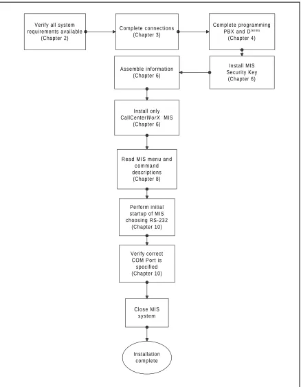
Chapter 6 Installation of CallCenterWorX
NDA-24213 Page 10
NDA-24213 CHAPTER 2 Page 11 System Requirements
Variations in Setup
CHAPTER 2
System Requirements
1. Variations in Setup
The CallCenterWorX ACD Client/Server architecture allows one or more Maintenance Administration Terminal (MAT) computers to program and monitor the ACD system. The ACD computer can then provide call-handling data to an MIS application (which is not a Client) for translation into meaningful statistics and reports. The MIS application can be loaded as part of the complete CallCenterWorX suite, or used alone on one or more remote MIS PCs. Each MIS application maintains an independent database. See this chapter, Heading 7, “CallCenterWorX MIS PC Support.”
The installation CD-ROM contains three main installation options, which are:
1. CallCenterWorX suite, consisting of CallCenterWorX ACD, with the option to install the Server and MAT Client or only the MAT Client, plus CallCenterWorX MIS.
2. CallCenterWorX ACD, with the option to install the Server and MAT Client or only the MAT Client.
3. CallCenterWorX MIS.
The CallCenterWorX suite (including MIS) installation, choosing the ACD Server and MAT Client, requires the CCWX Version 2 Security Key and Sentinel drivers (drivers are automatically installed with Server installation procedure).
The CallCenterWorXACD Server and MAT Client installation requires Microsoft Windows NT 4.0 with Service Pack 5, a CCWX Version 2 Security Key, and Sentinel drivers (drivers are automatically installed with Server installation procedure).
The CallCenterWorX ACD MAT Client installation will run alone on Microsoft Windows NT 4.0 with Service Pack 5, Windows 98, or Windows 95 with OSR 2.5 4.00.1111 for Year 2000 compliance. It does not require a Security Key or Sentinel drivers.
• The complete suite (including MIS) installation using the MAT Client requires an MIS Security Key and Sentinel drivers (drivers are automatically installed with MIS installation procedure).
The CallCenterWorX MIS installation will run alone on Microsoft Windows NT 4.0 with Service Pack 5, Windows 98, or Windows 95 with OSR 2.5 4.00.1111 for Year 2000 compliance. It requires an MIS Security Key, and Sentinel drivers (drivers are automatically installed with MIS installation procedure).
CHAPTER 2 NDA-24213 Page 12
System Requirements
ACD Computer (Client or Server) With and Without MIS
2. ACD Computer (Client or Server) With and Without MIS
The following hardware, software, and information are required to install the CallCenterWorX ACD computer using TCP/IP.
Table 2-1 System Requirements for ACD Computer With and Without MIS
Note 1: Must have video card and driver to support 1024 x 768 resolution
Note 2: CallCenterWorX Version 1 Security Key will not be compatible with this version of the application. CallCenterWorX ACD MAT Client without Server does not require a Security Key unless installed with MIS, which will require an MIS Security Key.
Note 3: CallCenterWorX ACD MAT Client without Server can also use Microsoft Windows 95 or Windows 98. Windows 95 OSR 2.5 4.00.1111 is required for Year 2000 compliance.
Note 4: Not required when using PN-CC01.
Minimum Requirements Computer Pentium 266 Mhz processor or higher
64 MB RAM or more
30 MB available hard-disk space or more 15” or larger SVGA monitor Note 1
1 floppy-disk drive or other data storage device 4X CD-ROM drive
1 parallel port for connection of Security Key MS-compatible mouse
Network card (such as 3Com Etherlink III)
Computer Hardware CallCenterWorX Version 2 Security Key Note 2
Software
NEAX2000 IVS Series 1700 software or higher (1900 or higher for INFOLINK) Microsoft Windows NT 4.0 with NT Service Pack 5 or higher Note 3
CallCenterWorX CD-ROM installation disk Information IP address information for PBX
PBX Hardware NEAX2000 IVS PBX
Circuit board PN-CC00 or PN-CC01 Circuit board PN-AP01
Circuit board PN-2DATA (optional card for announcements) 48-TW-0.3 Connecting Cable
CC00 Ethernet Cable Note 4
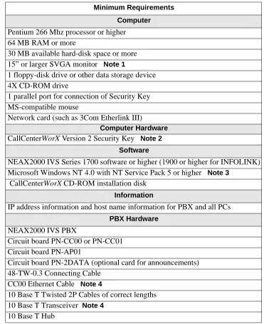
NDA-24213 CHAPTER 2 Page 13 System Requirements ACD Computer with MIS Using Remote MIS PC via TCP/IP
3. ACD Computer with MIS Using Remote MIS PC via TCP/IP
The following hardware, software, and information are required to install the CallCenterWorX ACD computer communicating with a remote MIS PC via TCP/IP.
Table 2-2 System Requirements for ACD Computer Using Remote MIS PC via TCP/IP
Note 1: Must have video card and driver to support 1024 x 768 resolution.
Note 2: CallCenterWorX Version 1 Security Key will not be compatible with this version of the application. CallCenterWorX ACD MAT Client without Server does not require a Security Key unless installed with MIS, which will require an MIS Security Key.
Note 3: CallCenterWorX ACD MAT Client without Server can also use Microsoft Windows 95 or Windows 98. Windows 95 OSR 2.5 4.00.1111 is required for Year 2000 compliance.
Note 4: Not required when using PN-CC01.
Minimum Requirements Computer Pentium 266 Mhz processor or higher
64 MB RAM or more
30 MB available hard-disk space or more 15” or larger SVGA monitor Note 1
1 floppy-disk drive or other data storage device 4X CD-ROM drive
1 parallel port for connection of Security Key MS-compatible mouse
Network card (such as 3Com Etherlink III)
Computer Hardware CallCenterWorX Version 2 Security Key Note 2
Software
NEAX2000 IVS Series 1700 software or higher (1900 or higher for INFOLINK) Microsoft Windows NT 4.0 with NT Service Pack 5 or higher Note 3
CallCenterWorX CD-ROM installation disk Information
IP address information and host name information for PBX and all PCs PBX Hardware
NEAX2000 IVS PBX
Circuit board PN-CC00 or PN-CC01 Circuit board PN-AP01
Circuit board PN-2DATA (optional card for announcements) 48-TW-0.3 Connecting Cable
CC00 Ethernet Cable Note 4
10 Base T Twisted 2P Cables of correct lengths 10 Base T Transceiver Note4
CHAPTER 2 NDA-24213 Page 14
System Requirements
ACD Computer with MIS Using Remote MIS PC via RS-232 Serial Connection
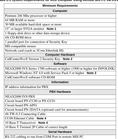
4. ACD Computer with MIS Using Remote MIS PC via RS-232 Serial Connection
The following hardware, software, and information are required to install the CallCenterWorX ACD computer communicating with a remote MIS PC via an RS-232 serial connection.
Table 2-3 System Requirements for ACD Computer Using Remote MIS PC via RS-232
Note 1: Must have video card and driver to support 1024 x 768 resolution.
Note 2: CallCenterWorX Version 1 Security Key will not be compatible with this version of the application. CallCenterWorX ACD MAT Client without Server does not require a Security Key unless installed with MIS, which will require an MIS Security Key.
Note 3: CallCenterWorX ACD MAT Client without Server can also use Microsoft Windows 95 or Windows 98. Windows 95 OSR 2.5 4.00.1111 is required for Year 2000 compliance.
Note 4: Not required when using PN-CC01.
Minimum Requirements Computer Pentium 266 Mhz processor or higher
64 MB RAM or more
30 MB available hard-disk space or more 15” or larger SVGA monitor Note 1
1 floppy-disk drive or other data storage device 4X CD-ROM drive
1 parallel port for connection of Security Key MS-compatible mouse
Network card (such as 3Com Etherlink III)
Computer Hardware CallCenterWorX Version 2 Security Key Note 2
Software
NEAX2000 IVS Series 1700 software or higher (1900 or higher for INFOLINK) Microsoft Windows NT 4.0 with Service Pack 5 or higher Note 3
CallCenterWorX software CD-ROM
Information IP address information for PBX
PBX Hardware NEAX2000 IVS PBX
Circuit board PN-CC00 or PN-CC01 Circuit board PN-AP01
Circuit board PN-2DATA (optional card for announcements) 48-TW-0.3 Connecting Cable
CC00 Ethernet Cable Note4 10 Base T Transceiver Note4
10 Base T Twisted 2P Cable of correct length Serial Hardware
NDA-24213 CHAPTER 2 Page 15 System Requirements Remote MIS PC Using TCP/IP
5. Remote MIS PC Using TCP/IP
The following hardware, software, and information are required to install a CallCenterWorX remote MIS PC using TCP/IP.
Table 2-4 System Requirements for Remote MIS PC via TCP/IP
Note 1: Must have video card and driver to support 1024 x 768 resolution.
Note 2: Windows 95 OSR 2.5 4.00.1111 is required for Year 2000 compliance.
Minimum Requirements Computer Pentium 266 Mhz processor or higher
64 MB RAM or more
30 MB available hard-disk space or more 15” or larger SVGA monitor Note 1
1 floppy-disk drive or other data storage device 4X CD-ROM drive
1 parallel port for connection of Security Key MS-compatible mouse
Network card (such as 3Com Etherlink III)
Computer Hardware MIS Security Key
Software
Microsoft Windows NT 4.0 with Service Pack 4, or Windows 95, or Windows 98 Note 2
CallCenterWorX software CD-ROM
Information
IP addresses and host name information for PBX and ACD and remote MIS PCs Hardware
CHAPTER 2 NDA-24213 Page 16
System Requirements Remote MIS PC Using RS-232
6. Remote MIS PC Using RS-232
The following hardware, software, and information are required to install a CallCenterWorX remote MIS PC using serial RS-232 connection.
Table 2-5 System Requirements for Remote MIS PC via Serial RS-232
Note 1: Must have video card and driver to support 1024 x 768 resolution.
Note 2: Windows 95 OSR 2.5 4.00.1111 is required for Year 2000 compliance.
Minimum Requirements Computer Pentium 266 Mhz processor or higher
64 MB RAM or more
30 MB available hard-disk space or more 15” or larger SVGA monitor Note 1
1 floppy-disk drive or other data storage device 4X CD-ROM drive
1 parallel port for connection of Security Key MS-compatible mouse
Computer Hardware MIS Security Key
Software
Microsoft Windows NT 4.0 with Service Pack 5 or higher, or Windows 95, or Windows 98 Note 2
CallCenterWorX software CD-ROM
Hardware ACD computer connected to PBX
NDA-24213 CHAPTER 2 Page 17 System Requirements CallCenterWorX MIS PC Support
7. CallCenterWorX MIS PC Support 7.1 Multiple MIS PCs
CallCenterWorX provides the ability to have up to eight MIS PCs.
• The integrated MIS application on the main CallCenterWorX Server is controlled by the main CallCenterWorX system security key and is counted as one of the eight PCs.
• Each additional MIS PC requires a separate MIS security key.
It is important to know that each additional MIS PC is a separate MIS application. This means that the additional PC is not a Client to the main CallCenterWorX MIS, but maintains its own database.
• While an MIS PC application is online, it will collect data received from the ACD.
• If the MIS application is terminated or the PC it is running on is shut down, data collection stops.
If a true Client/Server MIS PC application is required, NEC Global Navigator 3.03 or higher will perform that function.
7.2 IP Connections
The CallCenterWorX ACD provides eight IP connections for MIS PCs or Infolink.
• If you are using the MIS at the main CallCenterWorX Server, then you have seven remaining connections to use for other MIS applications or Infolink.
• If you are using the MIS at the main CallCenterWorX Server and are utilizing Infolink, there are six remaining IP connections for additional MIS applications to use. Each additional connection usage diminishes the MIS IP connections available.
CHAPTER 2 NDA-24213 Page 18
System Requirements
Multi-tenant MIS Considerations—Split Numbering
8. Multi-tenant MIS Considerations—Split Numbering
The assignment of split numbers in the CallCenterWorX MIS is relative to the number of tenants being served by the entire system (which can be as many as 9 tenants). A single MIS application can number only one usable Split 1 in the system. It does not employ the naming conventions used by the ACD, which starts numbering for each tenant at Split 1 (such as Tenant 1 Split 1, Tenant 2 Split 1, Tenant 3 Split 1).
To allow for the total split numbers assigned to any previous tenants, a single MIS application must “name but not use” a number of splits equal to the total for all previous tenants before numbering usable splits for a new tenant. In a multi-tenant situation with more than one or two tenants, this requirement rapidly uses up the 30 split numbers available to a single MIS application, while the ACD may have more split numbers still available.
As shown in Table 2-6:
• Although the ACD can start split numbering in Tenant 2 with “Split 1,” the MIS must number that split as “Split 4” because numbers Split 1, Split 2, and Split 3 have already been used in Tenant 1.
• The “Cumulative Total for System” row in the table shows a total of only 5 split numbers (3+2) used by the ACD after Tenant 2, but a total of 8 split numbers (3+5) have been used by the MIS after Tenant 2, due to the numbering of three splits in Tenant 1 which must be “named but not used” in Tenant 2.
• After Tenant 3, the ACD has used a cumulative total of 9 split numbers (3+2+4) while the MIS has used a cumulative total of 17 split numbers (3+5+9), with 8 of those being “named but not used.”
Note: Shaded cells in the MIS columns of Table 2-6 indicate the split numbers “named but not used” to allow for the MIS numbering system.
Table 2-6 Single MIS Application Split Number Usage
This limitation can be overcome by using a dedicated MIS application for each one or two tenants (there are nine possible tenants and eight possible IP connections for MIS applications), which would allow both the ACD and the MIS full benefit of all the allocated split numbers for the system. The use of multiple MIS PCs is discussed in the previous heading (Heading 7, “CallCenterWorX MIS PC Support”). Within the number of allowed IP connections, an ample number of MIS applications can be used to provide all needed services to tenants.
If multi-tenant usage is to be spread over the full ACD capacity of nine tenants, use NEC Global Navigator 3.03 which provides true multi-tenant capability as well as a Client/Server MIS PC application.
ACD MIS ACD MIS ACD MIS
1 1 1 1 1 1
2 2 2 2 2 2
3 3 3 3 3
4 4 4
Numbers for Splits 5 5
6 7 8 9
Total Split #s Used ACD 3 2 4
Total Split #s Used MIS 3 5 9
Cumulative Total for System 3 3 5 8 9 17
NDA-24213 CHAPTER 3 Page 19 Connection Drawings Installing the PN-CC00 and the PN-AP01
CHAPTER 3
Connection Drawings
Figure 3-1 PN-CC00 Connection through 10 Base T Transceiver 1. Installing the PN-CC00 and the PN-AP01
STEP 1: Mount the PN-CC00 in any slots LT10 (AP0) - LT15 (AP05). The PN-CC00 requires two LT (AP) slots.
STEP 2: Mount the PN-AP01 in any slot LT10 (AP0) - LT15 (AP05).
STEP 3: Set the PN-AP01 SENSE 0 switch to the slot number that is programmed in CM05 (see Chapter 4, Heading 1, “AP01 Initialization”).
STEP 4: Install the 48-TW-0.3 connecting cable from the DCB A connector of the PN-CC00 card to the bottom connector of the PN-AP01 card.
STEP 5: Install the Ethernet cable from the AB Ether connector of the PN-CC00 card to the 10 Base T transceiver.
STEP 6: Install the Ethernet cable from the transceiver to the network driver of the Server. Note: One end of this cable must be reversed.
1.1 Crossover Reverse Pin-out
Figure 3-2 Crossover Reverse Pin-out NEAX2000 IVS
PN-CC00
PN-AP01
10 Base T Transceiver
CallCenterWorX Server
Note: One end of this cable
must be reversed. 48-TW-0.3 Cable Ethernet Cable Cable Ethernet Interface Cards Crossover/Reverse
T TxD+ 1 1 TxD+ TxD- 2 2
TxD-RxD+ 3 3 RxD+
RxD- 6 6
RxD-NOTE:
1. Pins 4,5,7,and 8 not used.
CHAPTER 3 NDA-24213 Page 20
Connection Drawings
Installing the PN-CC01 and the PN-AP01
2. Installing the PN-CC01 and the PN-AP01
Figure 3-3 PN-CC01 Connection Straight to ACD Computer (Client or Server)
STEP 1: Mount the PN-CC01 in any slots LT10 (AP0) - LT15 (AP05). The PN-CC01 requires one LT (AP) slot.
STEP 2: Mount the PN-AP01 in any slot LT10 (AP0) - LT15 (AP05).
STEP 3: Set the PN-AP01 SENSE 0 switch to the slot number that is programmed in CM05 (see Chapter 4, Heading 1, “AP01 Initialization”).
STEP 4: Install the 48-TW-0.3 connecting cable from the DCB A connector of the PN-CC01 card to the bottom connector of the PN-AP01 card.
STEP 5: Install the Ethernet cable from the RJ-45 connector of the PN-CC01 card to the ACD computer (Client or Server) communicating via TCP/IP.
Note: One end of this cable must be reversed. NEAX2000 IVS
PN-CC01
PN-AP01
CallCenterWorX Server
Note: One end of this cable must be reversed. 48-TW-0.3 Cable
Ethernet Cable Interface
NDA-24213 CHAPTER 3 Page 21 Connection Drawings PN-CC00 Connecting Through a Hub
3. PN-CC00 Connecting Through a Hub
Figure 3-4 PN-CC00 Connecting Through a Hub
STEP 1: The Ethernet cables going from the transceiver to the hub and from the hub to the Server and PCs are straight-through cables.
STEP 2: The Ethernet cable from the transceiver to the hub goes into a port other than Port 8 of an 8-port hub or Port 4 of a 4-port hub. The last port in a hub is usually used as an uplink port, connecting to a LAN, another hub, a bridge, a router, or other such device. Verify this with the manufacturer’s specifica-tions for the hub you are using, since some hubs use Port 1 for uplink instead of the last Port.
STEP 3: The Ethernet cables from the ACD computer (Client or Server) and from the MIS PC can go into any port that is not the uplink port.
3.1 Straight-Through Pin-out
Figure 3-5 Straight-Through Pin-out NEAX2000 IVS
PN-CC00
PN-AP01
CallCenterWorX Server 10 Base T
Transceiver Ethernet Cables 10 Base T Hub
Remote MIS PCs
Hub, Bridge remote MIS PC TCP/IP via hub
Remote ACD Client Interface
Cards
Straight-Through
TxD+ 1 TxD- 2 RxD+ 3 RxD- 6
1 TxD+ 2 TxD-3 RxD+ 6 RxD
-NOTE:
1. Pins 4, 5, 7, and 8 not used . 2. Use for going from 10
CHAPTER 3 NDA-24213 Page 22
Connection Drawings
PN-CC01 Connecting Through a Hub
4. PN-CC01 Connecting Through a Hub
Figure 3-6 PN-CC01 Connecting Through a Hub
STEP 1: The Ethernet cables going to the hub from the PN-CC01 and from the hub to the Server and PCs are straight-through cables.
STEP 2: The Ethernet cable from the transceiver to the hub goes into a port other than Port 8 of an 8-port hub or Port 4 of a 4-port hub. The last port in a hub is usually used as an uplink port, connecting to a LAN, another hub, a bridge, a router, or other such device. Verify this with the manufacturer’s specifica-tions for the hub you are using, since some hubs use Port 1 for uplink instead of the last Port.
STEP 3: The Ethernet cables from the ACD computer and from the MIS PC can go into any port that is not the uplink port.
NEAX2000 IVS
PN-CC01
PN-AP01
CallCenterWorX Server
10 Base T Hub
Remote MIS PCs 10 Base T Cable
Ethernet Cables Interface
Cards
NDA-24213 CHAPTER 3 Page 23 Connection Drawings PN-CC00 Connection for ACD Computer to Remote MIS PC Serially
5. PN-CC00 Connection for ACD Computer to Remote MIS PC Serially
Figure 3-7 PN-CC00 with RS-232 Serial Connection Note: In this diagram, it is assumed the remote PC is using CallCenterWorX MIS.
STEP 1: Follow the procedures in this chapter, Heading 1, “Installing the PN-CC00 and the PN-AP01,” to connect the PN-CC00 to the ACD computer.
STEP 2: Connect one end of the RS-232 serial cable to a COM Port on the ACD computer.
STEP 3: Connect the other end of the RS-232 serial cable to a COM Port on the remote PC which will be running the CallCenterWorX MIS program.
STEP 4: Configure the ACD computer and the remote MIS PC by following the procedures in Chapter 5, “Configuration Procedures.”
Remote MIS PC
RS-232 Cable PN-CC00
PN-AP01
CallCenterWorX Server NEAX2000 IVS
10 Base T
Transceiver
Ethernet Cable Interface
CHAPTER 3 NDA-24213 Page 24
Connection Drawings
PN-CC01 Connection for ACD Computer to Remote MIS PC Serially
6. PN-CC01 Connection for ACD Computer to Remote MIS PC Serially
Figure 3-8 PN-CC01 Connection for ACD Computer to Remote MIS PC Serially Note: In this diagram, it is assumed the remote PC is using CallCenterWorX MIS.
STEP 1: Follow the procedures in this chapter, Heading 2, “Installing the PN-CC01 and the PN-AP01,” to connect the PN-CC01 to the ACD computer .
STEP 2: Connect one end of the RS-232 serial cable to a COM Port on the ACD computer.
STEP 3: Connect the other end of the RS-232 serial cable to a COM Port on the remote PC which will be running the CallCenterWorX MIS program.
STEP 4: Configure the ACD computer and the remote MIS PC by following the procedures in Chapter 5, “Configuration Procedures.”
R em ote M IS PC
RS-232 C able PN-C C01
PN-AP01
CallCenterWorX Server NEAX2000 IVS
Ethernet Cable Interface
NDA-24213 CHAPTER 3 Page 25 Connection Drawings Connecting Wall Display Boards
7. Connecting Wall Display Boards
Connections from the computer running CallCenterWorX MIS to the Spectrum Wall Display Board may vary according to the specific model of board. Instructions should be obtained from Spectrum Corporation
regarding the model you are installing.
• The computer must be configured to output data to the board through a COM Port.
• Wall boards may be used in a “chained” series following connection specifications from Spectrum Corporation.
Figure 3-9 PN-CC00 Connecting ACD Computer or MIS PC to Wall Boards See Figure 3-11 for connection of RS-232 cable into the COM Port on the back of the Host.
NEAX2000 IVS
Ethernet Cable
RS-232 Cable
NEC Custom er Service NEC ... Sales
NEC ... NTAC
LW C :0 :00 G O S :10 0 %
COM Port
CallCenterWorX Com puter
Wallboards
PN-CC00
PN-AP01 Interface Cards
CHAPTER 3 NDA-24213 Page 26
Connection Drawings
Connecting Wall Display Boards
Figure 3-10 PN-CC01 Connecting ACD Computer or MIS PC to Wall Boards
As shown in Figure 3-11 below, the RS-232 Cable connects to the COM Port designated as an MIS Port (see Chapter 5, Heading 1.3, “ACD Computer Setup for Use with Remote MIS PC via RS-232”).
Figure 3-11 Connection of RS-232 to COM Port NEAX2000 IVS
PN-CC01
PN-AP01
Ethernet Cable
CallCenterWorX Computer COM Port
RS-232 Cable
Wallboards
NEC Customer Service
NEC ... Sales NEC ... NTAC
LWC:0:00 GOS:100% Interface
C ards
NDA-24213 CHAPTER 4 Page 27 Programming the PBX and the Dterm
AP01 Initialization
CHAPTER 4
Programming the PBX and the D
term1. AP01 Initialization
DESCRIPTION DATA
For the IVS (CP00 and CP03):
Assign the slot number to the PN-AP01 board according to the location of the board.
Note: The slot number is given by the SENSE 0 switch on the PN-AP01 board.
(1) Slot number (04-15) (2) PN-AP01 board
For the IVS 2000 Series Software (CP16): Assign the slot number to the PN-AP01 board according to the location of the board.
Note: The slot number is given by the SENSE 0 switch on the PN-AP01 board.
Y= 0
(1) Slot number (04-15) (2) PN-AP01 board
For the IVS2 (CP14):
Assign the slot number to the PN-AP01 board according to the location of the board.
Note: The slot number is given by the SENSE 0 switch on the PN-AP01 board.
Y = 0
(1) Slot number (04-15) (2) PN-AP01 board
ID code all clear with AP. To clear the AP per-perform the following:
Note: Switch 1 on the PN-AP01 must be set as follows:
OFF
ON
After clearing the AP01, change SW1-2 and SW1-3 back to the “ON” position.
CM05 START CMD6 END INITIAL INITIAL INITIAL
ST + D60 + DE + 0000 + DE + CCC + EXE
CHAPTER 4 NDA-24213 Page 28
Programming the PBX and the Dterm
Programming the ACD Position Prime Line and My Line
2. Programming the ACD Position Prime Line and My Line
DESCRIPTION DATA
For the IVS (CP00 and CP03):
Assign the primary extension. (1) LEN 0000-0511
(2) FXXXX Station number
For the IVS 2000 Series Software (CP16):
Assign the primary extension. (1) LEN X00-X63 (X = PIM No. 0-7)
(2) FXXXX Station number
For the IVS2 (CP14):
Assign the primary extension. (1) LEN X00-X63 (X = PIM No. 0-7)
(2) FXXXX Station number
For the IVS (CP00 and CP03):
Assign the ACD virtual line and ACD Pilot numbers.
Note: Use LEN 0000-0127 ONLY.
(1) LEN 0000-0127 (2) Virtual number
For the IVS 2000 Series Software (CP16): Assign the ACD virtual line and ACD Pilot numbers.
Note: Use LEN 000-127.
Using the PZ-M537 MP expansion card allows LEN 000-255 to be monitored.
(1) LEN 000-127 (2) Virtual number
For the IVS2 (CP14):
Assign the ACD virtual line and ACD Pilot numbers.
Note: Use LEN 000-127.
Using the PZ-M537 MP expansion card allows LEN 000-255 to be monitored.
(1) LEN 000-127 (2) Virtual number CM10
START
NDA-24213 CHAPTER 4 Page 29 Programming the PBX and the Dterm Programming the ACD Position Prime Line and My Line
DESCRIPTION DATA
Assign the ACD virtual line to the My Line.
(1) Primary Extension (CM10) (2) ACD virtual line (CM11)
Assign ACD virtual line for originate suppress.
Assign ACD Pilot number as monitored number.
Assign ACD Group number.
(Y) = 1
(1) ACD virtual line (2) 2: Originate suppress
(Y) = 1
(1) ACD Pilot number (2) 3: Monitored number
(Y) = 2
(1) XXXX ACD Pilot number (2) 00-15 Group number
Note: Only assign the ACD Pilot number.
Tenant (Y) = 04
(1) X-XXXX (ACD Position, Agent, and Pilot)
(2) 01 Tenant 01
09 Tenant 09
END CM93
CM17
CHAPTER 4 NDA-24213 Page 30
Programming the PBX and the Dterm Programming ACD/OAI Operation Codes
3. Programming ACD/OAI Operation Codes
START
END
DESCRIPTION DATA
OAI function key assignment. Note: Cannot use F1032.
Op-codes are fixed to function names (see OAI key code assignment table below).
(Y) = 0
(1) F1033 OAI key 1
F1047 OAI key 15 (2) 128 - 191 MSF 192 - 255 TMF
Assign IP address.
Example:
1st Data 00 01 02 03 IP Address 101 022 033 055
(Y) = 9
(1) 00: First Octet
03: Fourth Octet
(2) XXX: First Octet
XXX: Fourth Octet
OAI Key Code Assignment
Function Name OAI Key Code OP Code Function Key Code
Break 1 187 F1033
Auto/Manual 2 252 F1034
Work 4 253 F1036
Night 5 188 F1037
Trunk/Trouble 6 250 F1038
Tally 7 189 F1039
Assist 8 254 F1040
Emergency 9 255 F1041
Log On/Off 10 190 F1042
Monitor 12 191 F1044
Call Waiting 14 249 F1046
CMD7
NDA-24213 CHAPTER 4 Page 31 Programming the PBX and the Dterm
Programming Dterm Key Assignment
4. Programming Dterm Key Assignment
DESCRIPTION DATA
Assign OAI keys to ACD station. (YY) = 00
(1) My Line, key no. (2) F1033: OAI key 1
F1047: OAI key 15
Assign ACD virtual line key. (YY) = 00
(1) My Line, key no.
(2) XXXX: ACD virtual line CM90
START
CHAPTER 4 NDA-24213 Page 32
Programming the PBX and the Dterm Programming ACD Group Announcements
5. Programming ACD Group Announcements
START DESCRIPTION DATA
For the IVS (CP00 and CP03):
Assign a Digital Announcement Trunk Circuit No. to the required LEN.
Note: The Digital Announcement Trunk Circuit No. must be assigned to the first LEN (level 0) and/or the third LEN (level 2) of each LT slot.
(1) LEN (0000 - 0512) (2) EB002 - EB127
PIM 0/1: EB000 - EB031 PIM 2/3: EB032 - EB063 PIM 4/5: EB064 - EB095 PIM 6/7: EB096 - EB127
For the IVS 2000 Series Software (CP16): Assign a Digital Announcement Trunk Circuit No. to the required LEN.
Note: The Digital Announcement Trunk Circuit No. must be assigned to the first LEN (level 0) and/or the third LEN (level 2) of each LT slot.
(1) LEN X00-X63 (X = PIM No. 0-7) (2) EB002 - EB127
PIM 0/1: EB000 - EB031 PIM 2/3: EB032 - EB063 PIM 4/5: EB064 - EB095 PIM 6/7: EB096 - EB127
For the IVS2 (CP14):
Assign a Digital Announcement Trunk Circuit No. to the required LEN.
Note: The Digital Announcement Trunk Circuit No. must be assigned to the first LEN (level 0) and/or the third LEN (level 2) of each LT slot.
(1) LEN X00-X63 (X = PIM No. 0-7) (2) EB002 - EB127
PIM 0/1: EB000 - EB031 PIM 2/3: EB032 - EB063 PIM 4/5: EB064 - EB095 PIM 6/7: EB096 - EB127
Assign the function for each Digital Announcement Trunk.
YY = 00
(1) 000-127: Digital Announcement Trunk Circuit No. assigned by CM10.
(2) 16XX Message Group No.
(02-63) for Multi-connection
announcement service for OAI.
CM10
NDA-24213 CHAPTER 4 Page 33 Programming the PBX and the Dterm Programming ACD Group Announcements
DESCRIPTION DATA
Assignment of Digital Announcement Trunk No.
Y = 2
(1) 000-127
(2) 1XXX
002-127:Digital Announcement Trunk No.
UCD Delay Announcement detection / OAI Announcement connection timer.
Y = 0
(1) 67
(2) 01-32
END CMD7