A Sensitivity Investigation upon the Dynamic Structural Response of a
Nuclear Plant on Aseismic Isolating Devices
I. MICHELI ANSALDO ENERGIA Nuclear Division I-16161 Genova, ITALY A. COLAIUDA ENEA Accelerator Driven System Project I-40129 Bologna, ITALY
1. ABSTRACT
The ADS (Accelerator Driven System) is a hybrid reactor, basically consisting of an ion-beam accelerator and of a subcritical reactor, currently developed in Europe as an innovative and inherently safe concept for nuclear high-level waste management and power generation.
Object of this paper is a sensitivity analysis of the behaviour of a typical isolating device in an application for the Nuclear Island of an ADS Plant, with a preliminary assessment of isolation main effects on the building response under a reference design basis earthquake excitation.
After a general description of isolators and main underlying principles, an estimation is given of different building responses under a seismic load for classical foundations and for two different types of isolators, making use of a three dimensional finite element model of the building and of simplified extrapolations.
The comparison is focused on the acceleration floor response spectra at the reactor support level, a basic concern in the main vessel seismic design.
Specific criteria for the design verification of the isolating system are also investigated.
2. SEISMIC ISOLATORS
2.1 Basic Principles of Seismic Isolation
Seismic isolation is one of the most significant engineering developments in recent years: several examples of application to bridges, non-nuclear plants and structures already exist in highly seismic areas, like Japan, California and European countries (like Italy and Greece).
Unlike the conventional design approach, which is based upon an increased resistance (strengthening) of the structures, the seismic isolation concept is aimed at a decrease of dynamic loads induced by the earthquake at the base of the structures themselves.
This concept has proven especially reliable for the prevention of damage to non-structural members and inner equipment (like typically existing in nuclear plants).
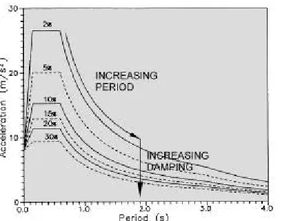
Seismic isolation is practically obtained by means of an insertion of special devices (the “isolators”) between the base of the structure and its foundations. Isolators must have a high flexibility, so as to move the fundamental periods of the main structure well beyond the range associated to the soil motion amplification (see Figure 1): this can be easily achieved for medium or hard soil, whereas a particular care is required for applications upon soft soils. As a result, the soil excitation is filtered and accelerations at the base of the structure are drastically reduced.
Figure 1 - Acceleration response spectrum as a function of damping (from Eurocodes EC8 for
ground acceleration 0.8g and medium soil)
Figure 2 - Displacement response spectrum as a function of damping (from Eurocodes EC8 for
ground acceleration 0.8g and medium soil)
SMiRT 16, Washington DC, August 2001 Paper # 1814
In principle, a structure may be isolated in both horizontal and vertical directions: at present, however, seismic isolation is usually limited to horizontal directions. The main reason is that seismic loads are generally quite lower in the vertical direction (due to lower soil excitation levels and to a reduced amplification across the structure); also, 3-D isolation design is rather complicated by potential rocking modes of vibration.
The strong reduction in structural accelerations has its obvious reverse in large rigid-body displacements, which are to be limited by means of dissipating elements, leading to significant increases of structural damping (see Figure 2).
Isolators should also have a high self-centring capability, i.e. the capability of carrying back the isolated structure to its initial position after each peak of seismic excitation, a safety feature with respect to potential earthquake aftershocks. Finally, the horizontal stiffness of isolation devices, which is quite low at large excitations, should be, on the contrary, high enough at low excitations, as typically induced by small earthquakes or winds, in order to avoid significant vibrations in case of these relatively frequent events.
All basic principles of seismic isolation have been successfully integrated in the HDRB (High Damping Rubber Bearing), a recently developed 2-D isolator, which has been selected for application to the ADS Nuclear Island.
2.2 Main Features of the HDRB
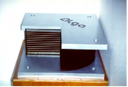
The HDRB is a steel-laminated bearing consisting of alternate layers of rubber and steel plates bonded by vulcanisation: it is able to support high vertical loads with negligible deflection, still providing an efficient isolation with respect to the horizontal seismic excitation [1] (see Figure 3).
This device is very efficient as regards both filtering and dissipation functions, the main effects of which are:
§ the fundamental frequency of the isolated structure is moved in the low range (between 0.33 and 1 HZ), where the seismic motion energy is very low;
§ the structure displacements in case of large earthquakes are reduced below allowable limits, by means of a large amount of energy dissipation.
Figure 3 - Typical High Damping Rubber Bearing Figure 4 - Typical load/deflection plot of a HDRB
With respect to standard isolators, the HDRB peculiar characteristics are:
§ a high damping capability due to a large area of the hysteresis loop (see Figure 4): the equivalent viscous damping is not less than 10% of critical damping;
§ a highly proven good self-centring capability;
§ a high horizontal stiffness at low excitations, so as to minimise the effects of frequently occurring events (like wind loads): the wind control region of shear strain is 2÷5%, as the earthquake region is 50÷125%;
§ the horizontal stiffness, quite low in the large deformation range, increases again for shear strains exceeding 200%, which is useful to avoid excessive displacements even for extremely strong earthquakes;
§ a very high vertical stiffness, in order to withstand deadweight and vertical seismic loads, as well as to prevent rocking movements during seismic excitation;
§ the fixation to the structure is not based on friction but on positive connections, namely by recess or dowels (see Figure 5) or by bolt joints (see Figure 6);
§ the mean lifetime is over 60 years.
Figure 5 - HDRB with fixation by recess (type A) Figure 6 - HDRB with fixation by bolts (type E)
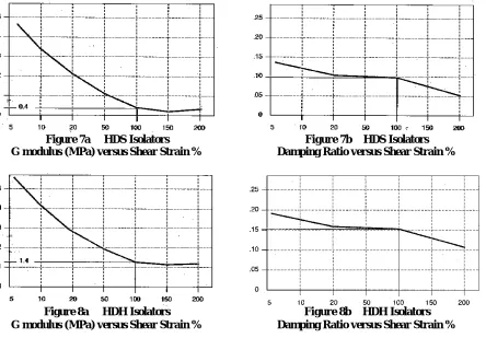
Stiffness and damping characteristics are shown in following Figures 7 and 8 and in Tables 1a and 1b for HDRB isolators with soft rubber compound (HDS) or hard rubber compound (HDH) [2].
Figure 7a HDS Isolators
G modulus (MPa) versus Shear Strain %
Figure 7b HDS Isolators
Damping Ratio versus Shear Strain %
Figure 8a HDH Isolators
G modulus (MPa) versus Shear Strain %
Figure 8b HDH Isolators
Damping Ratio versus Shear Strain %
It is shown that the damping ratio of these isolators is nearly constant for shear strains between 20 and 100%: its value is about 0.10 for soft/medium compounds and about 0.15 for hard compounds. The horizontal stiffness, nearly constant for shear strains between 100 and 200%, rises to several times more for shear strains of 5%: at 100% shear strains, soft and hard compound shear moduli G are, respectively, about 0.4 and 1.4 N/mm2.
Table 1a. Dimensions and Properties of HDS.A Isolators
Table 1b. Dimensions and Properties of HDH.A Isolators
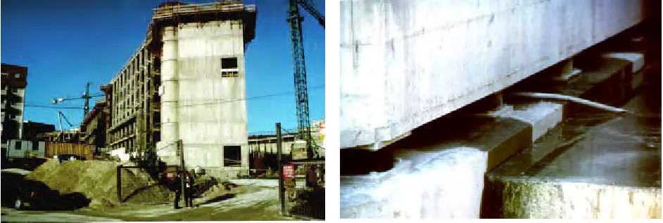
The HDRB isolators have already been employed in the aseismic design of several important civil and industrial buildings and structures. Among the most impressing applications [1]:
a) the Telecom Centre in Ancona (Italy), see Figures 9 and 10; b) the Corinth Canal Bridge (Greece), see Figures 11 and 12;
c) the Riace’s Bronzes in Reggio Calabria (Italy), see Figures 13 and 14; d) the chemical plant in Visp (Switzerland), see Figures 15 and 16;
e) the bridge over Tagus River in Santarem (Portugal), see Figures 17 and 18.
Figure 11 - Corinth canal bridge under construction Figure 12 - HDRB sketch for Corinth canal bridge
Figure 13 - The maquette of a Riace’s Bronze on its antiseismic support during tests
Figure 14 - Detail of the segmented HDRB
Figure 17 - The bridge over Tagus River in Santarem, central part
Figure 18 – Bridge over Tagus River: disposition of the HDRB on the piers of the main span
2.3 Isolation Design
The isolating system is to be designed to withstand dead, live and seismic loads.
The best-fit isolator layout should minimise the global torsion mode of the supported structure, so as to get nearly uniform horizontal displacements: this can be achieved along with a stiffness centre of the isolation system as close as possible to the projection of the centre of mass of the isolated structure onto the plane of isolators.
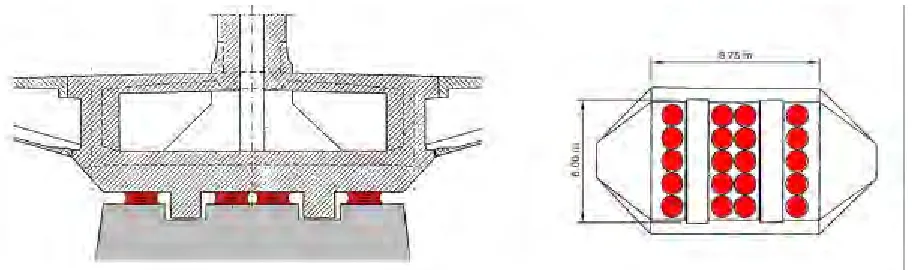
Isolators should be at least located under load concentrations zones such as main walls. Also, for an easy in-service inspection, they should be installed on concrete pedestals in a gap between a lower and an upper basemat, at an adequate mutual distance.
As to the dynamic behaviour, the isolator choice is based upon the following procedure:
a) calculation by hand of main horizontal isolation frequency: fi = (√(K/M))/2π, with M total mass of the isolated
building and K global horizontal stiffness of the isolation system ( fi should be in the range 0.33-1 Hz);
b) verification of the expected isolation frequency by means of a finite element model of the building and evaluation of the mean isolator horizontal displacement and associated shear strain and efficient stiffness; c) subsequent iterative calculations of isolator displacements and stiffness until convergence is reached.
3. APPLICATION TO ADS NUCLEAR ISLAND BUILDING
3.1 FEM Model
The general arrangement of the ADS Nuclear Island buildings is shown in Figure 19. Figure 20 shows the ADS Reactor Vessel and main Components.
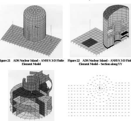
The 3-D finite element model of the building structures was built up by means of ANSYS Computer Program [3] (see Figures 21 thru 23). Beam elements were used for the simplified stick models of auxiliary buildings, whereas the reactor building was simulated by shell elements and the reactor containment wall by solid brick elements; the main component, the reactor vessel supported by the containment, was represented by a simplified beam model reproducing the main horizontal mode of vibration.
Figure 19 – ADS Nuclear Island Buildings – General Arrangement
Figure 20 – ADS Nuclear Reactor Vessel and Main Components
The dynamic excitation corresponding to a SSE (Safe Shutdown Earthquake) was simulated by means of the EUR free-field design response spectra, with a ZPA acceleration of 0.25 g along each global direction.
The overall finite element model with isolators has a total of 14817 active degrees of freedom.
Figure 21 ADS Nuclear Island – ANSYS 3-D Finite
Element Model
Figure 22 ADS Nuclear Island – ANSYS 3-D Finite
Element Model – Section along YY
Figure 23 ADS Nuclear Island – ANSYS 3-D Finite
Element Model - Structures inside Reactor Wall
Figure 24 Considered Layout of Isolating Devices
3.2 Choice of Isolators
Two types of isolators were investigated in the dynamic analysis of the ADS buildings: a) HDS.A900, with Kh = 1.25 kN/mm
b) HDH.A800, with Kh = 3.45 kN/mm,
Kh being the horizontal stiffness at 100% shear strain [2].
HDS (HDH) isolators are made from a soft (hard) compound rubber. The choice of HDS.A900 and HDH.A800 is related to the need of keeping the maximum vertical load on each isolator under the specific nominal limit, for each load combination taken into account: in this case, the combined maximum vertical load is given by the dead load plus the vertical component of the earthquake load (which is not reduced by the 2-D devices here investigated).
Assuming an isolator layout as shown in Figure 24 (an isolator at each of the upper basemat 267 nodes, underlying main walls of reactor and auxiliary buildings) with a uniform load distribution, the average load on isolators is thus:
1500000/267 ≅ 5620 kN (conservative evaluation).
Isolators referred to as HDS.A900 and HDH.A800 have maximum allowed vertical loads of 7700 and 7500 kN, respectively (see Table 1a and 1b), thus ensuring a 30% margin or more. However, for the considered buildings, these isolators should be equipped with the fail-safe system above mentioned (see § 2.2).
3.3 Evaluation of the Isolation Frequency
For both selected types of isolator, the first-approach theoretical isolation frequency is evaluated by the horizontal stiffness at 100% shear strain:
a) for isolators HDS.A900, fi=(√(K/M))/2π≅ 0.28 Hz, where K=Kh⋅N=1.25⋅267 ≅ 334 kN/mm and M ≅ 106150 t;
b) for isolators HDH.A800, fi≅ 0.47 Hz, with K=Kh⋅N=3.45⋅267 ≅ 921 kN/mm.
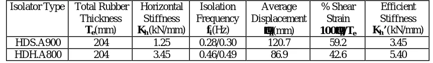
The actual dynamic response of the isolated building is checked by the ANSYS model, which includes the simulation of the isolator stiffness: spectral analysis results show that main calculated frequencies for selected isolators are in very good agreement with above theoretical values (see Table 2).
Table 2. Most Significant Response Parameters for Selected Isolators
Isolator Type Total Rubber Thickness
Te(mm)
Horizontal Stiffness
Kh(kN/mm)
Isolation Frequency
fi(Hz)
Average Displacement
δδh(mm)
% Shear Strain
100δδh/Te
Efficient Stiffness
Kh’(kN/mm)
HDS.A900 204 1.25 0.28/0.30 120.7 59.2 3.45
HDH.A800 204 3.45 0.46/0.49 86.9 42.6 5.40
Table 2 also reports the average displacements at the isolator locations and corresponding shear strains from maximum and minimum SRSS horizontal displacements (combined along X and Y) at isolator top faces, as issued by ANSYS for a 3-D earthquake load combination (it is to be noted that horizontal displacements of an isolated building are uniform only in the ideal case of an isolator stiffness centre on the vertical projection of the global centre of mass, in which case the torsion mode is not excited). We observe that in a case like this, in which, due to isolation, nearly 100% of the building mass participates to a single mode (in both X and Y directions), a first approach value of the horizontal displacement due to earthquake may be obtained from the first mode displacements (by combining X and Y contributions). This is not completely true for the considered building, as a little error is brought about by an interaction between the first mode along Y and the torsion mode (see Sect. 3.5).
As the shear strain is lower than the assumed 100%, an iterative process should follow to achieve convergence between the assumed stiffness and the resulting shear strain (linked by the non-linear relationships of Figures 7 and 8 ).
This is done by a simplified by-hand approach through following steps:
a) an efficient stiffness Kh’ is drawn from diagrams giving the stiffness variation of the considered isolators with
the shear strain percent (Figures 7 and 8);
b) a corrected value of isolation frequency (fi’) is evaluated from Kh’, by assuming a constant mass participation
to horizontal modes (same “M” in equation for fi): this is true in cases like this, with isolation frequencies far
from soil/structure interaction frequencies (as shown in Sect. 3.5);
c) a corresponding new value of horizontal displacement (δh’) may then be estimated from equation:
δh = as / ωi2 (1)
where ωi = fi/2π is the isolation pulsation (rad/s) and as the corresponding spectral acceleration;
d) subsequent iterations of above substeps provide new values of efficient stiffness, isolation frequency and shear strain for each considered isolator, until a satisfactory convergence is reached.
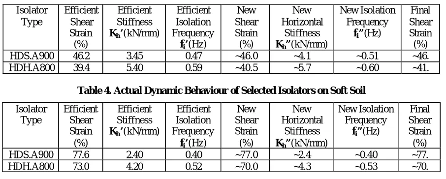
Table 3. Actual Dynamic Behaviour of Selected Isolators on Medium/Hard Soil Isolator Type Efficient Shear Strain (%) Efficient Stiffness
Kh’(kN/mm)
Efficient Isolation Frequency
fi’(Hz)
New Shear Strain (%) New Horizontal Stiffness
Kh”(kN/mm)
New Isolation Frequency
fi”(Hz)
Final Shear Strain (%)
HDS.A900 46.2 3.45 0.47 ~46.0 ~4.1 ~0.51 ~46.
HDH.A800 39.4 5.40 0.59 ~40.5 ~5.7 ~0.60 ~41.
Table 4. Actual Dynamic Behaviour of Selected Isolators on Soft Soil
Isolator Type Efficient Shear Strain (%) Efficient Stiffness
Kh’(kN/mm)
Efficient Isolation Frequency
fi’(Hz)
New Shear Strain (%) New Horizontal Stiffness
Kh”(kN/mm)
New Isolation Frequency
fi”(Hz)
Final Shear Strain (%)
HDS.A900 77.6 2.40 0.40 ~77.0 ~2.4 ~0.40 ~77.
HDH.A800 73.0 4.20 0.52 ~70.0 ~4.3 ~0.53 ~70.
3.4 Verification of the Isolating System
The isolating devices should meet the following criteria [6], [7]:
a) the differential displacement between top and bottom of isolators, due to seismic load, should not exceed 3 Te;
b) the distance between the vertical projection of the global centre of gravity and the isolator centre of stiffness should be less than 0.05Dmax, Dmax being the maximum horizontal dimension (in this case 0.05Dmax≅ 3.85 m);
c) no tension load is allowed on any isolator for any load combination due to deadweight, earthquake or accidental load (verification against the uplift);
d) the overall mass associated to considered modes in the spectral analysis for horizontal excitation should not be less than 90% of the total building mass.
The above criteria are all fulfilled in the considered application, as:
a) from the calculated maximum displacements, we may observe that even in the case of soft compound isolators on soft soil, the maximum shear strain is below 100% (displacements less than Te);
b) the eccentricity associated to the assumed isolator layout is about 1.46 m < 3.85 m (from ANSYS model); c) a simplified approach may be used in this case for the uplift verification, showing that the eccentricity of the
resultant earthquake load in the worst case (for an upward directed vertical component of seismic excitation) is well inside the basemat ellipsis of inertia; in the most pessimistic case (for a soft soil):
ex = My / N = 238690/56028 ≅ 3.346 m < 1/6 Lx min ≅ 12.83 m
ey = Mx / N = 71334/56028 ≅ 1.273 m < 1/6 Ly min ≅ 6.17 m,
where ex (ey) are the eccentricities along X (Y), Mx (My) the rocking moments around X (Y), N the minimum
vertical downward load on foundations, Lx min = 77 m, the minimum basemat length along X, and Ly min = 37 m,
the minimum basemat length along Y;
d) the overall mass associated to the significant modes retained for the seismic analysis proves very close to 100% of the total building mass on isolators.
3.5 Seismic Isolation Main Effects
Table 5 resumes main issues of the ADS building modal analysis in the case of non-isolated foundations and for both considered types of isolation (HDS or HDH isolators on hard soil). Lines 1 and 2 of table give frequency and mass participation of horizontal vessel modes (very close to the expected target value of 4 Hz to which the vessel beam model was adjusted): it should be pointed out that vessel frequencies are far from those associated to global building modes for any type of foundations, but for foundations on medium soil. In this case, a significant dynamic coupling between vessel and connected reactor building is to be expected: this is confirmed by the increase in the effective mass (about 13000 t) participating to the first vessel mode along X (at 3.89 Hz), with respect to the vessel mass (2700 t).
Results also show that the first global modes for non-isolated foundations are mainly rocking modes, whereas in the case of seismic isolation they are associated to horizontal pure translation movements (see Figures 25 and 26); the torsion mode is only significant in the case of basemat on isolators (in this case, the torsion movement is essentially associated to the global mode along Y, due to the higher eccentricity along X, see § 3.4). The maximum horizontal displacements evaluated at the foundation level were about 157 mm for HDS isolators and 105 mm for HDH isolators (in the case of classical foundations, corresponding maximum displacements were about 30 mm).
Table 5. Frequency (Hz) and Participating Mass(t) of Main Vibration Modes
Soil-Structure Interaction Seismic Isolators
Hard Soil Medium Soil Soft Soil HDS HDH
Dominant Direction
Freq. P. M. Freq. P. M. Freq. P. M. Freq. P. M. Freq. P. M.
Vessel XX 3.94 2567 3.89 13031 4.07 2485 4.01 0.05 4.01 0.4
Vessel YY 3.95 2843 4.01 2345 4.11 2900 4.00 0.05 4.00 0.4
Global YY 6.92 61302 3.56 65617 1.26 67952 .277 79293 .460 79490
Global XX 8.52 66286 4.79 65094 1.63 79581 .282 104911 .468 104897
Torsion 10.80 4193 6.59 170 2.31 28 .296 25927 .492 25726
Vertical 16.77 39998 7.94 102868 2.64 103457 16.29 57644 16.29 57624
This effect is shown by Figures 27 thru 32, which give the floor acceleration response spectra calculated at the elevation of the main vessel support structure in the considered cases (non-isolated or isolated foundations, taking into account both selected isolators) for seismic horizontal excitations. Figures show that, in the case of basemat on seismic isolators, the spectral horizontal accelerations are drastically reduced (as expected due the low frequencies observed for main building modes) with respect to corresponding accelerations evaluated in the case of a non-isolated building. The comparison is performed for foundations on hard soil, but a similar effect could be observed for any soil: it may be observed that for medium/hard soils the most efficient isolation is obtained with HDS isolators.
Figure 25 –YY Main Mode without Isolation (6.92 Hz) Figure 26 –YY Main Mode with Isolation (0.46 Hz)
ADS - FRS Vessel Supports Elevation -0.5 m. Basemat on Hard soil - X Direction
0,0 0,5 1,0 1,5 2,0 2,5 3,0 3,5 4,0 4,5 5,0
0,1 1,0 10,0 100,0
Frequency (Hz) Accelerations (g) 1% 3% 5% 7%
ADS - FRS Vessel Supports Elevation -0.5 m. Basemat on Hard soil - Y Direction
0,0 0,5 1,0 1,5 2,0 2,5 3,0 3,5 4,0 4,5 5,0
0,1 1,0 10,0 100,0
Frequency (Hz) Accelerations (g) 1% 3% 5% 7%
Figure 27 – XX FRS without Isolation Figure 28 – YY FRS without Isolation
ADS - FRS Vessel Supports with Isolator HDS A900 Basemat on Hard soil - X Direction
0,00 0,05 0,10 0,15 0,20 0,25 0,30 0,35 0,40 0,45 0,50
0,1 1,0 10,0 100,0
Frequency (Hz) Accelerations (g) 1% 3% 5% 7%
ADS - FRS Vessel Supports with Isolator HDS A900 Basemat on Hard soil - Y Direction
0,00E+00 5,00E-02 1,00E-01 1,50E-01 2,00E-01 2,50E-01 3,00E-01 3,50E-01 4,00E-01 4,50E-01 5,00E-01
0,1 1,0 10,0 100,0
Frequency (Hz) Accelerations (g) 1% 3% 5% 7%
ADS - FRS Vessel Supports with Isolator HDH A800 Basemat on Hard soil - X Direction
0,00 0,05 0,10 0,15 0,20 0,25 0,30 0,35 0,40 0,45 0,50
0,1 1,0 10,0 100,0
Frequency (Hz) Accelerations (g) 1% 3% 5% 7%
ADS - FRS Vessel Supports with Isolator HDH A800 Basemat on Hard soil - Y Direction
0,00 0,05 0,10 0,15 0,20 0,25 0,30 0,35 0,40 0,45 0,50
0,1 1,0 10,0 100,0
Frequency (Hz) Accelerations (g) 1% 3% 5% 7%
Figure 31 – XX FRS with HDH.A800 Figure 32 – YY FRS with HDH.A800
4. SUMMARY AND CONCLUSION
The present investigation on the ADS NI building response under earthquake load has confirmed that the use of aseismic isolating devices moves global horizontal modes into the low frequency range, thus drastically reducing soil/structure interaction effects under a typical free-field seismic excitation, in particular, as far as accelerations at building floors are concerned.
The higher horizontal displacements induced on the building as a rigid body motion are not likely to create any significant problems at existing connections in a proper design.
Existing criteria for the global verification of the isolation system are also fulfilled.
As a concluding remark, an isolated nuclear island appears as the most adequate choice whenever the main component design is governed by the seism-induced loads.
5. ACRONYMS
ADS Accelerator Driven System EUR European Utility Requirements FRS Floor Response Spectra HDRB High Damping Rubber Bearing HDS (HDH) Soft (Hard) Compound HDRB
NI Nuclear Island
SRSS Square Root of the Sum of the Squares SSE Safe Shutdown Earthquake
SSI Soil Structure Interaction ZPA Zero Period Acceleration
6. ACKNOWLEDGEMENTS
Ph. D. Marco Battaini of ALGA Technical Department, Milano, for the useful information and photographs provided about the HDRB Isolator and its applications.
7. REFERENCES
1. Marioni, A., Jornadas Portuguesas de Engenharia de Estruturas Lisboa, LNEC, November 25 to 28, 1998
2. Catalogue High Damping Rubber Bearing
Algasism HDRB – 20123 Milano, I.
3. ANSYS – Engineering Analysis System – Revision 5.2
Swanson Analysis System Inc. August 31, 1995 4. ASCE 4-86 ASCE Standard September 1986
Seismic Analysis of Safety Related Nuclear Structures and Commentary on Standard for Seismic Analysis of Safety Related Nuclear Structures
5. ANSALDO Document ADS 2 TCLX 0202 Rev.0
Calculation Report – NI Buildings – Seismic and Static Analysis
6. Linea guida per progettazione, esecuzione e collaudo di strutture isolate dal sisma
Ingegneria Sismica, Anno XIV, N. 1, Gennaio-aprile 1997 Pubblicazione autorizzata dal Consiglio Superiore dei LL.PP.
7. Extension of the Available Design Guidelines for Seismically Isolated Nuclear Power Plants to 3-D Systems