If
1/'5
SERIAL NO. _ _ _ _ _RW-300 DIGITAL CONTROL COMPUTER
PROGRAMMING MANUAL
March, 1961
This manual is the property of the TRW Computers Company. It is made available to customers, prospective customets, and others, with the understanding that the contents of the manual shall not ~e released to any third party.
The R W -300 Digital Control Computer
The RW ... 300 Digital Control Computer is used for closed-loop control of industrial' proces se s, for autom.atic testing, for on-line data interpretation, and for simulations.
In real~time control and test applications, the RW-300 communicates
directly with instruments which measure or sense operating variable s. Under the direction of the program stored in memory, the RW-300 uses information from these instru-ments, performs calculations, reduces data, and generates the control signals re quired to fulfill proce s s or te st
objectives. Fail-safe features incorporated in the system equipment and program, coupled with the inherent reliability of the R W -300, ensure dependable operation.
The computer operator is generally advised of operating conditions by typed records -- printed out either periodically or on
demartd. Further, the operator is able to supply the RW -300 with special data whenever the process or test must be
IN THIS PROGRAMMING MANUAL.
Section I . . . contains a general de scription of the R W -300 and peripheral equipment.
Section II . describes the operation codes used in preparing instructions for the computer.
Section III. tells how the instructions are assembled into programs.
Section IV. introduces a programming technique which make s maximum use of 'computer time.,
Section V. . . contains detailed information relating to the digital input and output equipment used with the RW -300.
Section VI tells how programs are loaded into the computer under the direction of a program stored permanently in
computer memory.
Section VII . . details the functions of R W -300 controls and indicators.
Section VIII. . c'ontains reference material pertaining to number systems and scaling.
A Glossary of computer terminology is included at the end of the manual.
\ '
The ,last pages of the manual contain reference tables that are useful in preparing programs for the R W -300.
OTHER PUBLICATIONS ARE AVAILABLE.
A list of programming aids and mathematical subroutine s contained in
the RW -300 Program Library can be obtained by writing to TR W Computel\s
Company. \,
A manual describing Optimum Programming Using Symbols (OPUS)
in~ludes instructions for preparing programs in symbolic form.
TABLE OF CONTENTS
SECTION ,I - - GENERAL DESCRIPTION
I,~'
CHARACTERISTICS
~t
EXTERNAL FEATURES
Il':lSTRUCTION SYSTEM
WORD LENGTH
MEMORY . . . .
Basic Memory . .
Expanded Memory
ARITHMETIC UNIT . •
A Register.
B Register. C Register.
Adder
CONTROL UNIT
Y Register.
N Register.
Track Register
Instruction Register.
DIGITAL INPUT AND OUTPUT
ANALOG INPUT AND OUTPUT
.
.
.
.
.
.
Conver sion Capabilitie s . .
.
.
.
"
.
Input Conver sion Range and Numbe r Repre sentation •
Input Storage Locations • ',' . . . .
, Output Conver sion Range and Number Representation • .
Output Storage Locations
MAGNETIC TAPE UNIT
Introduction
.De scription . .
.
.
.
Operation "~,I • •
. .
.
.
..
.
••
• • ••
Specifications PAGE
1-1
1-2 1-3 1-4 1-4 1-4 1-5 1-61-6
1-61-7
1-7
1-7
1-8
1-8
1-8
1-9 1-9 1-11 1-11 1-14 1-16 1-161-18
1-18
1-18 1-191-21
·TABLE OF CONTENTS -- Continued
SECTION II -- INSTRUCTIONS
INTH.ODUCTION.
.
. .
.
.
.
.
. .
. .
.
.
. . . .
.
.
.
.
.
.
.
.
.
.
. .
.
.
.
.
.
LOAD A • • • • e, • • • • • • • • • • • • • • • • • • • • • • • • • • • • • • • • • • •LOAD B
·
.
. . .
.
. .
.
.
.
.
.
.
.
.
.
.
.
.
.
.
.
.
. .
.
.
. .
.
.
.
.
.
. .
LOAD A NEGATIVE.
.
.
. .
.
.
.
.
.
.
.
. .
.
.
.
.
.
. . .
.
. .
. .
.
.
.
.
.
STORE ASTORE B
ADD
· .
.
.
.
. .
.
.
.
.
.
.
.
. .
. .
.'.
.
.
.
.
'.
.
.
.
.
.
. .
.
.
.
. .
.
.
·
.
.
.
.
.
.
.
.
.
.
.
.
.
. .
.
.
. .
.
.
. . .
.
.
.
.
.
.
.
. .
.
.
. .
.
• • • • • • • • • • • '0 • • • '0' • • • • • • • • • • • • • • • • • • • • •
SUBTRACT
SHIFT
·
.
.
. . .
.
.
.
.
.
.
.
. . .
.
.
. .
. .
.
.
.
.
.
.
.
. . .
. .
.
.
. .
· .
. .
. . .
. .
.
.
.
.
.
.
.
.
.
. .
.
.
.
. .
. .
.
...
.
.
.
. .
.
.
.
TRANSFER ON NEGATIVE
.
.
.
'.'.
.
. .
.
.
. .
.
~. . .
. .
.
.
.
.
. .
.
TRANSFER ON ZERO •••••
.
.
.
".
. .
.
. .
. .
.
.
. .
.
.
.
.
.
.
.
.
.
.
.
TRANSFER ON OVERFLOW.
.
.
.
.
.
.
. . .'
.
.
.
. .
.
.
.
.
.
.
.
. .
. .
COMPARE MAGNITUDE.
.
.
. .
.
.
.
.
.
.
.
.
.
.
.
.
.
.
.
.
.
. .
. .
.
.
.
EXTRACT·
.
.
.
.
. .
.
.
.
. . .
.
.
. .
.
.
.
.
. .
.
.
.
.
.
.
.
.
.
.
.
.
.
.
.
MERGE.· .
.
.
. .
.
.
. . . .
.
.
..
.
.
.
.
. . .
. .
. .
. . .
.
.
. . .
. . .
.
.
.
SWITCH·
. .
.
.
.
. .
.
.
.
.
.
.
.
.
. .
.
.
. .
.
.
.
.
.
.
.
.
.
.
.
. . .
.
.
. .
STOP .•·
.
.
.
.
.
.
.
.
.
.
.
. . .
.
.
.
.
. .
.
.
.
.
.
.
.
.
.
.
.
.
. .
.
.
.
.
.
DIGITAL· .
.
.
.
. .
.
.
.
.
.
.
. .
. .
.
.
.
.
.
. . . .
.
. .
.
.
.
.
.
.
.
.
.
.
NO OPERATION.
.
.
.
.
..
.
.
.
.
.
.
.
. .
.
.
.
. .
.
. . .
... .
.
.
TAPE • • • e· • • • • • • • • • • • • • • • • • • • • • • • • • • • • • • • •MULTIPLY
·
..
.
.
.
. . .
.
.
.
. . .
.
. .
.
.
.
.
. .
.
.
.
.
.
.
. .
DIVIDE·
.
.
.
. .
.
. . .
.
.
.
. .
.
".
. .
'.
.
.
.
.
.
.
.
.
. .
.
.
. .
.
.
.
. .
.
EFFECTS ON REGISTERS.
.
.
.
.
.
.
.
. .
. .
.
.
.
.
.
.
.
.
.
.
.
.
.
.
.
PAGE
2-1 2-2 2-2 2-3
2 .. 3
TABLE OF CONTENTS -- Continued SECTION IU r BASIC PROGRAMMING
INTRODUC TION • • • • • • • • • • • • • • • • • • • • • • • • INSTRUCTION WORDS • • • • • • • • • • • • • • • • • • • FORMAT FOR LISTING INSTRUCTIONS • • • • • • • • DATA WORDS, OR CONSTANTS • • • • • • • • • • • • • • FORMA T FOR LISTING CONSTANTS • • • • • • • • • • • USE OF MEMORY •••
.
.
• • • • • • • • • • ••
•
•
• ••
•
••
•
•
•
•
• ••
• • ••
••
• • ••
• • • • • • • • •· ... .
• • • • • ••
•
• • • • • ••
• • • • •General • • • • • • • • • • • • • • •
•
• • • • ••
• • • • • • ••
••
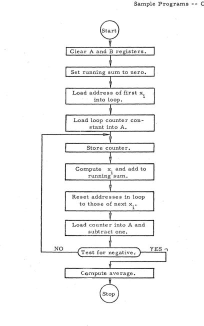
• • • Reading Information from Memo~y • • • • • • • • •Storing Information in Memory • • • • • • • • • • • • Organization of Li'stings • • • • • • • • • • • • • • • • Record Keeping • • • • • • • • • • • • • • • • • • • • • SAMP LE PROGRAMS • • • • • • • • • • • • • • • • • • • • • • •
Example I Example U Example
m
TABLE OF CONTENTS -- Continued
SECTION IV -- OPTIMUM PROGRAMMING
INTRODUCTION 0 • • • • •
. MEMOR Y ORGANIZATION. • ..
Tracks 00 through 07 • .
Tracks 08 through 15' ...
Tracks 08 through 61 . .
Track 62
Track 63
.EXPANDED MEMORY
. SELECTING OPTIMUM MEMORY LOCATIONS. .
Load, Merge, and Extract o • •
Add and Subtract. 0 0
Multiply and Divide .
Compare .Magnitude .
Transfer
Switch I
.
,..
Shift
No Operation _ 0
. Store
Digital.
e , • • 0 . , • 0 • •
..
.
.
. .
~. COMPARISON OF OPTIMUM AND SEQUENTIAL PROGRAMMING
REVOLVER o 0 • 0 . ,
EXPANDED MEMORY . .
OPTIMUM PROGRAMMING USING SYMBOLS
PAGE 4-1 4-3 4-3 4-3 4-5 4~6· 4-7 4-7 4.-9 4~13 4-14 4-1.4 4.-15 4-15 4-16 4-17 .'{ 4-17
: I. 4-17
" . .,
4-18
4-19
4-!9
4-21
'TABLE OF CONTENTS ... - Continued
DIGIT AL INPUT AND OUTPUT SECTION V
INTRODUCTION . . .
. .
.
.
.
.
.
.
.
. . .
·
.
·
. .
.
.
.
.
.
.
. .
.
.
.
.
.
DIGIT AL COMMAND..
.
.
.
.
.
.
.
.
.
.
.
••
·
.
. . .
.
.
.
.
. .
.
.
.
.
.
.
BASIC INPUT -'OUTPUT CAPABILITIES· .
.
. .
.
.
.
.
.
.
. .
.
.
.
.
Inputs ••••.
. .
.
.
.
.
• •·
.
. .
.
.
. .
.
.
.
• • • • o' • • •Inputs from Toggle Switches
. .
.
.
.
.
.
. .
. .
.
.
.
.
.
.
.
Inputs from Flexowriter • • • • • • • • • • • • • • • • • • • • • • • •Output to Flexowrite r • • • • • • • • • • • • • • • • • • • • • • •
Sample Printout Listing • • • • • • • • • •
EXPANDED INPUT-OUTPUT CAPABILITIES.
.
.
.
.
.
.
. .
.
. .
.
.
.
.
.
.
.
. .
.
.
.
.
.
.
.
.
Inputs. ~Outputs
.
. .
.
. .
. . .
.
.
.
.
. .
.
.
.
.
.
.
.
.
.
.
.
. .
.
.
.
.
. . .
..
.
. .
.
• • • • • • • • • • • • • • • • • • • • • • • • • ct •One - Bit Outputs • • • • • • • • • • • • • • • 0 • • • • • • • • • • • • • • •
Multi-Bit Outputs
.
.
.
. .
.
.
.
.
.
.
.
.
.
.
.
. .
.
. .
.
.
. .
INPUT -OUTPUT EQUIPMENT • • • • • • • • • • • • • • • • • • • • • • • • •Digital Indicator s . • • • • •
Twenty-Four -Hour Clock
.
.
.
. .
.
.
.
.
.
.
. .
.
.
. .
. .
.
.
. .
.
.
. . . .
.
.
.
.
.
. . . .
.
.
. .
.
. . .
Manua 1 Inputs
Watchdog Timer
Ferranti Reader
Teletype Punch
FLEXOWRITER • • • • •
·
.
.
.
.
.
.
.
.
.
.
.
.
.
.
.
.
.
. .
.
.
.
.
· .
.
.
.
. .
.
.
.
.
. . .
.
.
.
. .
.
.
.
.
. . . .
. .
·
. .
.
.
.
.
. .'
.
. .
.
.
.
.
. .
.
. . .
.
.
.
.
. . .
.
.
.
.
.
.
.
.
.
.
.
. .
.
.
.
.
. .
.
.
.
.
.
.
.
.
.
.
.
. .
.
.
.
.
. . .
.
. .
.
.
.
.
.
.
.
Mode s of Flexowrite r Ope ration·
. . .
.
.
.
.
. .
.
.
.
.
.
.
.
.
.
Gene ral Flexowrite r Characteristics . • • • • • • • • • • • • • • •Paper Tape. . • • • • • • • • • • • • • • • • • • • • • • • • • • • • •
Parity Checking
.
.
.
.
. . .
.
.
.
.
.
.
. .
.
.
.
.
.
. .
.
.
.
.
Flexowrite r Code s.
.
.
.
.
.
.
.
.
.
.
.
.
.
. .
.
. . .
.
.
. .
. .
.
.
Flexowrite r Timing Conside rations.
.
.
.
.
.
.
.
.
.
.
. .
.
. .
TABLE OF CONTENTS -- Continued
SECTION VI -- PROGRAM LOADING
, INTRODUCTION. . LOAD PROGRAM
'STANDARD PUNCHED TAPE FORMAT DECIMAL PUNCHED TAPE FORMAT OPERATING 00NDITIONS
MEMORY SUMS . . BINAR Y LOADING
JUMP INSTRUCTION
.
.
. . .
.'.
PAGE
6-1
6-1
6-4
6-6
6-7
6-9
6-10
'TABLE OF CONTENTS -- Continued
SECTION VII OPERATING CONTROLS AND INDICI,\.TORS PAQE
'.
OPERATOR'S PANEL. • •
·
•·
•· ·
• • • • • • • • • • • • • • • • ••
• • 7-1 Power Controls·
•· ·
•.
• • • •·
• • • •·
• • ~•
• ••
·
• • • •Operating Controls
·
• ,/•
· ·
·
· ·
•·
•·
•·
•
• • •·
•7-2
TEST AND MAINTENANCE PANEL • •
•
• • • • • • • • ••
• • ••
••
• •7-3
Program Loading. • • • • • • •
•
• ••
••
••
••
• • • ••
• •••7-4
Maintenance
·
.
.
.
• • • • • • • • • • • • • • ••
••
• • • ••
• • •7-4
Ope ration • • • • • • • • • • • • • • • • • • • • • • • • • • • • • • • • • •
7-4
PROGRAM CHECK-OUT
·
.
.
• • • • •• •
• • • ••
••
• •• ••
• • • •••7-6
Fetch and Exe cute Buttons • • • • • • • • • • ••
• • ••
••
• •7-7
Run Button
.
·
.
•·
• • • •· ·
••
•
• ••
·
• ••
• ••
••
• • ••
•
l-7
State Indicators
·
· ·
• • • • •·
• • • • • • • ••
•
• ••
• •·
•7-7
TABLE OF CONTENTS -- Continued
SECTION VIII -- NUMBER SYSTEMS AND SCALING
READING COMPUTER NUMBERS • . • . • • • • • • • • • • • • • • • • • • •
NUMBER SYSTEMS
.
. .
.
. .
. . .
'.
. .
.
. .
. .
.
. . . .
. .
.
.
.
. . .
CONVERSIONS.
... . .
.
.
.
.
.
.
. . .
.
.
.
.
.
. .
. . . .
.
.
. .
Binary to Decimal • . • • • • • • • • • • • • • • • • • • • • • • • • • •Decimal to Octal
·
.
. . .
. .
.
. . . .
. . . .
.
.
.
.
.
.
.
.
.
.
.
.
.
Binary to Octal to Binary.
.
.
.
. .
.
.
. .
.
.
.
. .
.
.
.
.
. .
.
.
Decimal to Binary..
. .
. .
.
.
.
.
.
.
. .
.
.
.
.
.
.
.
.
.
.
. .
.
.
.
Octa 1 to De cimal·
.
. . .
.
. .
.
.
.
.
. .
.
. .
.
. .
.
.
.
. . .
. .
.
BINARY ARITHMETIC • • • • • • • • • • • • • • • • • . • • • • • • • • • • • • •OCTAL ARITHMETIC • • • • • • • • • • • • • • • • • • • • • • • • • • • • • • •
SCALING
.
. . .
.
. . .
.
. .
.
.
.
. .
.
. .
.
.
.
.
.
.
.
.
.
.
.
.
.
.
.
.
.
.
.
.
Introduction • • • • • • • • • • • • • ", • • • • • • • • • • • • • • ' •••••Fixed-Point Notation and Scale, Factor • • • • • • • • • • • • • • •
Shift Commands
·
. .
.
.
.
. .
.
.
. . .
. .
.
. .
.
. .
..
.
.
.
.
.
.
.
Multiply CommandDivide Command
.
.
. .
.
.
.
'.
.
. . .
.
.
.
.
.
.
.
.
.
.
.
.
.
.
.
· .
.
.
.
.
.
.
. .
. .
.
.
.
. .
.
.
.
.
.
.
.
.
.
...
PAGE
8-1
8-4
8-4
8-6
8-6
8-7
8-7
8~S
8-9
8-10
8-10
8-11
8-13
8-14
LIST OF ILLUSTRATIONS
,Figure 1-1
Figure 1-2
Figure 2-1
Figure 3-1
Figure 4-1
Figure 5-1
R W -300 and Peripheral Equipment 0 • 0 • 0
R W -300 and Magnetic Tape Unit
Commands and Registers
Flow Chart of Program Exa,mpleIII
RW-300Memory . . . 0 • • , 0 •
Segment of Punched Tape •
Figure 5-2 Table of Flexowriter Codes
Figure 7 -1 Te st and Maintenance Panel
Figure 7-2 Oscilloscope Display
REFERENCE TABLES (last 3 pages in manual)
Table of Powers of 2
Table of Non-Parity Flexowriter Codes
Table of Powers of 8
Table of-Equivalent Revolver Locations
Table of R W -300 Instructions
. .
.
.
. .
.
.
.
...
• • • 0 • • 0
PAGE
1-12
1-20
2-27
3-17
4-4
5-26
5-31
7-3
CHARACTERISTICS
SECTION I
GENERAL DESCRIPTION
The RW -300 Digital Control Computer is a stored-program, aerial computer employing a magnetic drum memory with a total capacity of
8,080 wor.ds.' .~.~ -300 .compliters' with an· expand~d memory have a total
memory capacity of 15, 776 words. The R W-300 word is composed of 18 binary digits.
A word may represent either numerical data (17 bits, with a sign bit),
or one half of a computer instr,uction. Two words form a complete
instruc-tion; one half of the instruction specifie s the memory location of the operand,
and the other half of the instruction specifies the memor y location of the next
instruction. The half-instruction containing the next-instruction addre ss
includes one of 21 basic operation codes, and the half-instruction containing
the operand addre B s include 8 an execution code. The b~sic instr uction codes
are modified by the execution code and the operand address to provide a
flexible command structure.
Continuously variable voltages from measuring instruments and
transducers are automatically converted to digital for.m and stored in the
RW -300'.s memory .. -without programmed instructions. Up to 1,024 of these
continuously variable "analog" input· signals can be accommodated. Com-putational results representing control information are automatically
Characteristics - - Oontinued
controllers or other:control devices. Up to 12'8 of these "al1alog" output
s~gnals can be provided.
Up to 511 on-off signals from diffe rent source s can be accepted by
tp.e computer, permitting input from digital clocks, switches, paper-tape
readers, etc. A like number of digital output signals can be provided fO,r
the control of motors, indicators, alarms, logging typewriters, paper-tape
punche s, etc.
In addition to possessing the input-output capabilities necessary for
real-time control, the RW-300 has been designed to provide the
reliability'
required for continuous service.
Subroutines and interpretive routines are available to extend the
ap-plication of the RW -300 to scientific and general-purpose computation.
EXTERNAL FEATURES
The console model of theRW -300 (see frontispiece) is desk size and
weighs approximately 600 pounds. It operates from 120-volt, 60-cps power,
and requires no special air conditioning. Power consumption is
approxi-mately 500 watts. Usually supplied in the console cabinet 36 inches high, 56
inches long, and 29 inches deep, the same basic computer can also, be
fur-nished in an upright, air -purged cabinet that is 84 inches high, 48 inches
long, and 24 inches deep.
Operating controls for the console model are mounted on the sloping
front edge of the cabinet and are accessible when the computer cover is
External Features - - Continued , \
and off, f~r starting, stopping, and resuming the progr{im stored in memorx',
and for loading new programs into the memory. Beneath the cover, a test
and maintenance pane 1 contains controls, indicators, and displays which
facilitate program check-out and computer maintenance. The operating
con-trols and indicators are described in Section VII of this manual.
INSTRU:CTION SYSTEM
or commands, many of which can be modified to permit a large number of
distinct operations. The operation codes control arithmetic operations,
logical operations. and peripheral equipment. Section II contains a brief
description of the instruction format, followed by a complete description of
, the operation codes.
The time required to perform arithmetic and logical operations
depends upon the relative locations in memory of the instruction and the
operand. Using the optimum programming techniques describeq: in Section
. "
IV, the time s (in millise conds) required to complete typical instructions are
as follows:
Add or Subtract 0.78 mB
Multiply, full length 2.99 ms
Divide, fu 11 length 3.12ma,
Transfer 0.65 rna
Load Register 0.65 ms
Word Length
WORD LENGTH
In the RW-300, the basic unit of information is a worq! A \vord
con-sists of 18 binary digits, or bits: a sign bit and 17 bits of abso lute magnitude.
The sign bit is zero for positive and one for negative. (See S~ction VIII for
an explanation of the binary number system.)
[ I.
11.
r
LL
1.:1
I I
.L
J
J
J
J
I.:
I
18 17 16 15 14 13
l~11 10
9
Sign Bitl 'Most-Significant Bit8
7 6 5 4 : 3
a
1
Least-Significant Bit!
A word may represent: a numerical value, one half of an instruction,
typewriter or punch symbols, or a bit pattern that can be used for control
purposes. Section III describes the form of instruction words and data words.
MEMORY
The memor y of the R W -300 is a magnetic drum, nine inches in
dialn-et(~ r and nine inche slang, which rotate s at a speed of 3600 rpm. The
mag-nr-tic drum may contain a basic 8,080 word memory or an expanded melnory of IS', 776 words .
. ~~sic Mer:nory
There are 7,936 words of general storage on 62, tracks of 128 words
each, 32 words of fast-access storage in a circulating register, and 128
words in one track for a permanently stored load program. A word titne
(the time required for one word on the drum to pass a given point) is O. 13
Memory -- Continued
general storage is 863 milliseconds. The 32-word circulating register, or
f'lrev.olver" p has an average access time of approxim,ately 2 milliseconds.
Any of the 7,936 word locations can be written into during program
loaq-ing by usloaq-ing control facilities on the RW-300 test and maintenance panel. In
the ,basic' computer, the 32-word revolver and l~ 024 word locations in eight
128-word tracks can be written into under pr'ogram control. Up to eight addi~
tional tracks of program-writable storage can be provided by adding a module
to the basic computer. However $ this additional program~writable storage is
r.educed by the number of tracks re served for the storage of analog input datao
The number of tracks re served for analog input data does not affect the
32·-word revolver nor the 1 ~ 024 words of program~writable memory available in
the basic computero
Expanded Memory
RW~300computers with an expanded memory have 15$ 776 words of
storage on 123 tracks o Notmally~ 'e~panded memory ma,chines have 1 / 536.
words of program-writable storage, although up to 16 additional tracks (2,048
words) of program~writable storage can be provided by the addition of an
extra module to the basic computer. The 16 additio'nal tracks will be reduced
by the number of tracks reserved for the storage of analog input data ..
The method of identifying memory focations on the drum is de scribed in
connect~on with a desc::ription of basic programming in Section III. More de~
tailed drum characteristics are presented in connection with the optimum
lYle mor y - - Continue d
programming techniques, access time in general storage can ,be greatly
reduced below the "average" access time of 8.3 milliseconds.
ARITHMETIC UNIT
The arithmetic unit is that part of the RW -300 which actually performs
arithmetic and logical operations under control of the program stored in
memory. The unit includes three circulating one-word registers (A, B, and
C) on the drum. In addition, it contains a serial adder and flip -flops used
for storage, time delay, and logical manipulations.
A Register
The A register, or accumulator. is located on the drum, and has a
capacity of 1 7 bits plus sign (one word). It is the principal arithmetic
register and holds the result of most operations. The A register can be
loaded from me mory, and the contents 'o[ the A register can be stored in the
memory. It has the capability of shifting left or right one binary place per
word time. In the operations of addition, subtraction, left shifting, and
division, overflow from the A register is possible (i. e .. J the computer may
attempt to put a one to the left of the 17th bit). When overflow occurs, the
overflow indicator is tu:t:'ned on.
B Register
The B register, located on the drum, has a capacity of 17 bits plus
sign. It holds, at various times, the multiplier, remainder, or
least-significant half of the double -length product. As in the case of the 'A register J
Arithmetic Unit -- Continued
can be stored in the memory. It has the ability to shift left one binary place
per word time. When shifting left, it is coupled to the A register so that the
bit in position 17 of the B register is shifted into position 1 of the, A register, C Register
The C register, located on the drum, also has a capacity of 17 bits
plus sign. Its operation is not under the control of the computer's program,
and therefore the programmer is se ldom concerned with, it. ,At various times.
the C register holds the multiplicand, divisor, subtrar.t.end, addend, or
execution code.
Adder
The adder forms; in one digit time, the sum of one bit from the
augend, one bit from the addend, and the carry bit from the p:revious addition.
It outputs the sum bit and the carry bit. Since the sum is formed serially,
bit by bit, the adder requires one word time to generate the sum of two 17 - '
bit numbers. (This should not be confused with the length of time required
to carry out an Add instruction. )
CONTROL UNIT
The control unit processes the instructions in the sequence dictated
by the program stored in memory. In processing an instruction, the control
unit pe rforms the following functions:
a. Obtains instructions from memory.
Control Unit -- Continued
c. Connects and activates other units by sending out i-q.dividual
com-mands to the other units in the prope rsequence to perform. the
desired function.
d. Initiates the transfer of information between units.
e. Stops the execution of the program.
f. Keeps track of time so that the various parts .of an instruction are
executed in the appropriate sequence.
pome of the components of the control unit are described below.
Y Register
The Y register is a one -word circulating register on the drum which
holds the operand address.
N Register
The N register is a one -word circulating register on the drum which
holds the address of the next instruction.
Track Register
The track register is a six-bit flip -flop register which holds the track
address when a program instruction refers to a memory location. The
flip-flops in this register also serve other purposes; for some instructions, the
track register supplements the instruction register. For digital input and
output instructions, the track register addre sses groups of input or output
Control Unit - - Continued
Instruction Register
The instructi,')n register isa five-bit flip-flop register which holds
the instruction code, but temporarily holds the executi0tl code when an
in-struction is being read from memory.
DIGIT AL INPUT AND OUTPUT
All digital input and output functions are accomplished by a single
operation code which controls the transfer of information between the A
register and external equipment. Digital outputs are in the form of relay ...
contact closures, and digital inputs are accomplished by sensing voltage
change s on input line s •
The RW -300 digital input-output facilities are extremely flexible.
The paragraphs which follow contain a description of the basic facilities and
a description of options available to customers. A more complete
descrip-tion, along with programming instructions, is included in Section V.
The basic digital input-output unit provided with the RW -300 is a
Flexowriter, which consists of an electric typewriter, a paper -tape and
edge -·punched card reader, and a paper -tape and edge -card punch. The
Flexowriter can read, punch, or print at the rate of 8 characters per second'.
In the basic computer, seven digital input line s are re se rved for accepting
information from the Flexowriter reader {or from some other input device},
. and 18 digital input lines are available for accepting information from digital
Digital Input and OutPllt - - Continued
Relays within the basic computer convert Flt,xowriter signal levels
to levels compatible with the digital input circuits. A negative five volts
applied tc:;> one or more of the other 18 digital input lines causes the
com-puter to read a one on that line when a digital input instruction is executed,
anp an open or positive voltage
L?2.
5 volts) causes a zero to be read.Although a group of 18 digital-output control line s is available for
system expansion, the basic computer contains only eight relays for
pro-viding digital outputs to the Flexowriter printing or punching circuits.
Au~iliary control relays are provided within the basic computer for
turn-ing the Flexowriter motor on and off; for initiating printing when a logging·
typewriter is used; for initiating punching when a high-speed paper-tape
punch is used; and for accepting "ready" 'signals from these output devices.
A variety of optional digital input-output equipment is available.
Addit~onal typewriters, including line printers, can be supplied to log out
raw data and finished computations. A Ferranti high-speed paper-tape
reader (60 characters/ sec) and a Teletype paper-tape punch (60 characters/
sec) can alternat~ with or be substituted for the Flexowriter reader and punch.
When used in control applications, the computer's basic digital input
capabilities can be expanded to accept 29 additional groups of digital inpu.t
lines (with 18 lines in each group) for a maximum of 540 digital input lines.
In an expanded digital input system, a zero is read into the computer when
an input line is grounded; a one is read when an input line is open.
Basic digital output capabilities can be expanded to provide 29
addi-tional groups of output lines (with 18 lines in each group) for a maximum of
Digital Input aq.p. Output - - Continued
The, additional equipment required for expansion of digital input and
,output facilitie s is accommodated in an operator I s de sk-type console shown
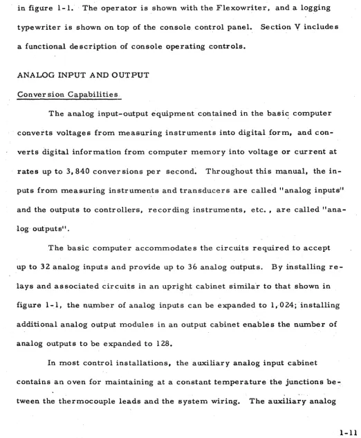
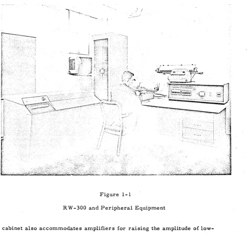
in figure 1-1. ' The operator is shown with the Flexowriter, and a logging
typewriter is shown on top of the console control panel., Section
V
include sa functional de scription of console operating controls.
ANALOG INPUT AND OUTPUT
Conver sion Capabilities,
The analog input-output equipment contained in the basi~ computer
converts voltages from measuring instruments into digital ,form, and
con-verts digital information from computer memory into voltage or current at
rates up to 3,840 conver sions per second~ Throughout this manual, the
in-puts from measuring instruments and transducers are called" analog inin-puts"
and the outputs to controllers, recording instruments, etc., are called
"ana--log' outputs".
The basic computer accommodates the circuits required to accept
up to 32 analog inputs and provide up to 36 analog outputs. By installing
re-lays and associated circuits in an upright cabinet similaor to that shown in
figure 1-1, the nuomber of analog inputs can be expanded to 1,0024; 'installing
additional analog output modules in an output cabinet enable s the number of
analog outputs to be expanded to 128.
In most control installations, the auxiliary analog input cabinet
contains an oven for maintaining at a constant temperature the junctions be ...
· Analog Input and Output Continued
!
Figure 1-1
RW -300 and Peripheral Equipment
cabinet also accommodates amplifiers for raising the amplitude of
low-level instrument signals (e. g., thermocouple voltages) to a low-level
com-patible with the computer's analog-to-digital conversion circuits. The
cabinet also contains filter s for removing hum and noise from incoming
instrument lines.
Equipment in the computer (and in the auxiliary analog cabinet)
Analog Input and Output - - Continued
measuring instruments is constantly convert.ed to digital iprn1, and the latp.st
digital representation is stored in memory without programmed instructions.
Similarly, when new operating parameter s have been conlputed and stored
in memory by the progranl, these latest values are converted to analog form
and transmitted to control instrumentation. The digital-to-analog
conver-sions are also performed automatically, and do not have to be programmed.
The analog converter is time- shared among inputs and outputs.
A nalog outputs are updated (adjusted to correspond to a number stored
in memory under program control) automatically at least once every 1/30
second. The frequency at which analog inputs are updated (input voltages
con-verted to digital form and stored in memory) depends upon the particular
in-sta,llation. For a basic system (32 voltage gates, 0 relays). the inputs can
be updated every 1/30 second; for a system employing 1, 024 inputs, the
in-put information stored in memory can be updated every second, but under
severe noise conditions,' where filters are employed. the inputs may be
up--:-dated every two seconds, four seconds, or eight seconds to allow a
stabiliza-tion period for the noise filter s. Actually, ,the analog input-output system is
flexible and is furnished to meet the needs of each application. Analo'g input
information can be converted and stored at the maximum rate' of 3,840 sam ...
pIes 'per second. Longer delays between input samplings are also possible
to provide a stabilization period for transducer s.
Systems can be changed or expanded by means of field modi.fications.
Analog Input and Output -- Continued
later, I?Y connecting' the analog outputs of the computer to controller s, can
pe expanded to an a~tomatic control system.
Analog signals other than d-c voltages, such as pressures, a-c
volt-ages, etc., are converted to d-c voltages by the use of transducers or
spe-cial converter s. Amplifier s and filter s are provided for low-level signals
from thermocouples and strain gages. Analog-to-digital and
digital-to-~nalog conversions are accurate to
±
0.,05 percentoi
full scaleo, '
Input Conve'rsion Rang~ and Number Representation
Two typ~\9.,of analo~ input capabilities are available: (1) a unipolar
converter which convert,s' to digital form voltages in the range from 0 to
+
10. 23 volts d-c, and (2) a bi-polar 'converter whi~h converts to digitalform voltages in the range from -100 23 volts to't'lO. 23 volts.
When conver~~d to :~igital form" the ~nalog 'signals are represented
by 10 binar y digits,.; Be~aus,e. the leas.t.~ significant digit repre sents a
con-version resolution of 10 millivoltEi, the' concon-versions are accurate to t 5
millivolts, or ± O~ 05 percent ~f full scale.
In a unipolar system, the digital equivalent of the analog output
sig-nal is contained in bit-positions 8 through 17 of a comput~r wor"d, with the
most ... sigp.ificant bit in position 17. Using a bi-polar system, the
magni-tude, bits are in bit-positions 8 through 17" and the sign bit, is, ~n
bit"'posi-tion 18 .
. As an example~ assum,e that one of. the variables to be measurfJd is
temperature~ and assume that the' range of values for the temperature
A nalog Input and 0 utput .. ,., Continued
of this variable can be developed by a thermocouple and art amplifier to take
the form of a volta~e with a rang'e O'fO to
10. 23
volts. Th~ analog subsystemwill sample this voitages develop a
10 ..
digit binary representation of thevoltage, and store it in a specified location on the magnetic d~um. The most
significant of these lO bits will be. in bit-position
17
of a compute,r word, theleast significant in bit-position 8. In a unipolar systems the sign bit and
bit positions 7 through 1 are set to zero for analog inputs and ignored for
analog outp.uts.. Since the exact memory location for eac'h input wHich is
conve,rted to digital for.m will be, krtown to th;e' progra:mmer, i.t will be neces ...
sar y for ,.the .p~ogr.a.m tp ~e.fer on,ly to that locati.on .and interpret the binar y
nut:rtbe·r storecl~
.A
ssumlng a linear relationship between degrees F:ahrenheit andvoltaget a table of values for thes:e representations could be as follows:
Degrees Fahte,nheit Volts B i.na~ yRe pre sentation
200
1i0
0' •.00'
00 00 00 00 0.0
2'00.5
0.0..1
00 00
O~00
01.to
5~0
0,10
00 00 00 . 10 10
.Z50q,
0
l,O.o00 01
I.O .010.0
325.0
2...50
00
11 1 110 10
450~0
5,00
01' 11"11 01 0,0
575. 0,
7. :50: lQ·11 10 11 10
Analog Input and Output .. - Continued
Input Stor age LocatiQns
Analog inputs are stored in tracks OB through 15 of the drum. If 128.
iq.puts are required, only track OB would be used, but for 1~ 024 inputs, tracks
OB through 15 would be required. Not all sectors of a track need be used for
inputs. The exact number of sectors and tracks used depends upon the
num-ber and type of inputs required for a particular system, and assignments are
made to minimize equipment requirements, cost, and memory space for the
partic ular applicationo
In a track reserved for analog input data~ unassigned sectors cannot
be used for general program storageo
Output Conver sion Range and Number Repre s~ntation
Each analog output is capable of controlling the voltage or current in
its load to an accuracy of
±
00 05 percent, and is capable of supplying acur-rent of 5 milliamperes to a transducer or' controller o
A maximum analog output current of 20 milliamperes can be supplied
at the customeri s option.
A binary number to be converted to analog form is written into a spe~
cific memory location by the program. The binary number for analog outputs
occu.,pies bit~positions B through 17 of the computer wordi with the most-sig~
nificant digit in bit'~position 17, and the least-significant digit in bit~position B.
For "voltage" type analog outputs, the voltage applied to a controller.
or trans.ducer may be from 0 to 100 23 volts. To apply 10. 23 volts to the load,
bit-p'ositions B through
11
of the correeponding memory sector are filled withAnalog Input and Output .. ,- Continued
and an analog output voltage is line·ar, so that the output voltage is equal
to the decilVal equivalent of the number in mem'ory (taking bit-posi,tion 8 as
the least-significant bit) times 0.01 volt. Three of the 1,023 possible values
are tabulated below.,
Binary Number in Analog '(Output Sector of Memo.x:·~
~ , "*=! 011111111110000000
010000000000000,000
.0000000011000'0000'0
Voltage Across Load (max. current = 5 rna)
10 .. 23 volts d···c
5. 12 volts d-c
0.06 volts d ... c
In some applications the voltage applied to the load (controller) is
not as important as the current through the loado For these applications
a precision resistor is placed in series with the load, and the analog out ...
put is connected to control the voltage acros s the precisi.on re sistor s thereby
./
controlling the current through the load. Although the relationship between
the load current and the number in memory is linear~ the number in
mem-ory must be scaled an amount determined by the ratio of the load/'Inetering
resistance. If the load and metering re sistance s are eq~al. one half of the
analog output voltage appears across the load~ and the other half appears
across the metering resistance. In this casei maximum curr'ent :tibrough
the lTc'ad and metering resistances is obtained when the program writes:
18 1
010000000000000000 /
in.the appropriate analog output sector. Writing a larger nl,lmber into the
Analog Input and Output"" - Continued
and the number in rpemory, and in some extreme cases might'damage that
specific analog output circuit.
The exact configuration of the analog output circuits (voltage output
or current output) i!? determined by the type of controller; transducer» in~'
strumentj/ etc. g that forms the load for the analog output. During the
plan-:-ning stage of an installation, the programmer is advis,ed of the limits»
linearity~ re sponse time, and other factor s that affect the program. The
sector numbers that will control analog outputs are also determined during
the planning stageo
Output Storage Locations
Analog outputs are taken fro·m track 07 by the analog co'nverter.
Track 07 is program writable; any portion not used for writing analog out,,·
puts may be used by the program for other storage purposes.
MAGNETIC TAPE UNIT
Introduction
The R W ~300 Magnetic Tape Unit provides practically unlimited mem,·
ory capacity for data reduction and control applications requiring more
stor-age than the basic drum memory provides.
The
computer and mag.netic tapeunit ferm a system that is used for on~Hne data acquisition and processingJ
for recording historical data, for table 100k.1up, and for preparing tape s for
analysis ... by an IBM 700-series data processing system. Data is then trans·,
ferred from the drum to the tape for temporary or permanent storage. For
Magnetic Tape Uni~ -- Continue'd
data is transfert'ed back to the compute,r. AUxiliary programs and subroutine~
~re also transferr.ed from 'tape' to the dru:rn. Transfer of digital data between
the tape 'unit and the computer is accomplished'through a magnetic core buffer.
Two models of the R W -300 Magnetic Tape Unit are available. If the
"standard" unit is employed, data stored on the tapes must be transferred
back to the R W - 300 for reduction and pre sentation. A nother model of the
R W -300 Magnetic Tape Unit, called the" compatible" tape unit, prepare s
magnetic tapes in a format that is acceptable to some models of IBM
mag-netic tape units. Thus, data stored by allcompatihle" R W -300' Magmag-netic Tape
Unit can be processed either by an IBM system; or by the R W -300.
De scription
The magnetic tape unit consists of one magnetic core buffer and from
one to eight magnetic tape transports. Figure 1- 2 shows the R W - 300 and
one element of a magnetic tape unit. In the figure; the six-foot rack contains
the buffer, buffer controls, and one tape transport with associated writing
and power supply circuits. Similar cabinets are used to accommodate ad~
ditional tape transports and associated writing and power supply circuits.
The buffer has a capacity of 128 computer words of 18 bits each.
This amount of information is commonly called a "block" in the standard
tape unit and a "record" in a compatible tape unit.
, In the ~:',ptandard" magnetic tape unit, a tape calibrator is used to
establish specific writable blocks (no defects) on the tape, and these blocks
Magnetic Tape Un~t - - Continued
Figure 1-2
R W -300 and Magnetic Tape Unit
blocks on the'tape. The tape calibrator automatically rejects any areas
of tape that are of low quality.
Format characteristics of a II compatible" magnetic tape unit
Magnetic T~:pe Unit - - Continued
of all records. Therefore p when a record is rewritten on a tape fnth.e
;1I.com-patible" system,. all succeeding records within a \I file" must also be rewrit-.
ten.
Each transport holds one reel of tape with a capacity of
approximate-ly 730, 000 [email protected] words for the II standard" unit and 1, OOO~ 000 computer
words for the" compatible" unit. The magnetic tape unit transfer s data at
the maximum usabl~ rate of 1,9 536 words per secondo' An eight ... transport
. s,ystem can record data a.lltomatically at th.e maximum rate for nearly 70
minutes. Since the ~ape reels are easily replacedp 'the dataurecording
per-iod may be eXtended indefinitely.
The transports are modified Ampex FR-400 digital tape handlers
operating at 75 inches per second in the write) search, and read modes and
rewinding at 160 inches per second. Each transport accommodates 2400
feet of standard 1 / 2~inch magnetic tape wound on a 10 1 / 2~inch reel.
, ,
The buffer is a specially designed assembly» which in additio.n to
the core storage includes control» parity generation and chec~ing» error
se:nsing~ timing$ and power circuits. Parity checking~ncierror s\:l:rveillanc'e
are provided to prevent los·$ and inaccuracy of data during transfers to and·
from magnetic tape.
Operation
The c.omputer program controls the norrnaill,9 automatic operation of
th~ magrietic tape unit.
The
'magnetic tape unit fU'rnishe s error -conditionsignals ~o aid this controL» and has manual controls and indicator s for
Magnetic Tape Unit - .... Continued
A single co~nputer command with a number of variations dete14mines
the mode of operation of the magnetic tape unit. This command causes the
unit to '~ransfer data$ search. rewind, or back spaceo Data is transferred
as follows:
a. from computer to buffer
b. from buffer to tape
c. from tape to buffer
d. from buffer to computer
To locate data recorded on tapeg the computer searches the tape
while it is traveling either forward or in reverse until a ·specified record
address (first word of the record) is foundo
The tape unit provides the computer with indications of six conditions
that interfere with the transfer of data. The se conditions are: a. buffer power supplies inoperative
b. buffer in use
c. tape error (parity violation)
d. transport inoperative
. e. end of reel
f4 write amplifiers disabled
During the last three conditions, the unit cause s the computer to st'op if
it
attempts to transfe~ data.
Computer commands related to the magnetic tape unit are described
b:cie£ly in Section
rI
f and more complete operating information is containedMagnetic
Tape'
Unit _ .. ContinuedSpecifications
Number of' buffers: one.
Number of transports: one to eight.
Power: 120 voltsl 60 cps.
Type of buffer: magnetic care.
Physical characteristics of buffer: mounted in one tape transport.
Capacity of buffer: 128 words of 18 bits each (one block), or 64 words
of 36 bits each' (one II record" in a "compatible"
system).
Type of tape transport: modified Ampex FR-400 Digital Tape Handler.
Dimensions of transport: 72 in. highll 23 in. wide, and 24 in. deep.
Recordirig De'nsity
Number of data bits
Number of timing bits
Number of parity bits
Tape width
Tape length
Tape
reelTape speed forward
or reverse
Tape rewind speed
Maximum bit rate
Minimum bit time
II Standard" Tape Unit
150 lines per inch, 8 bits per line
6'
I
1
1 / 2 in.
2400 feet
10 1/2 in.
75 i'n..,Iset:,., within
10/0
160 in. / sec.
11. 25 kps
89 J.ts.
"Compatible" Tape Unit 200 lines per inch,
7 bits per Litle
6
o
1
1 / 2 in.
2400 feet
10 1/2 in.
75 iri. / sec. $ within , 10/0
160 in. / sec.
15 kps
Magnetic Tape Unit - - Contif1u~d
"Standard" Tape Unit· 150 line $ per inch, Recording Density 8 bits pet. line
Record length (128 words) 2. 58 in.
Inter-record spacing 2. 72 ih.
Records per 2400-foof tape 5440
Allowable record 'number s .
21~
Record time 34. 4
ms.
. Maximum us.able data 1, ~36 wordsJ s,e,c. transfer rate:'
Number of heads 8 read; 8 write
"C'ornpatiblelt Tape Unit
200':Unes,' per i~ch, 7 bits per line
1.9Zin.
0.75in •.
10.800
Z18
.25. 6 ms •
SECTION II
INSTRUCTIONS
INTRODUCTION
An instruction in the RW -300 is composed of two computer words.
The first word contains an execution code. 'and an operand address. The
sec-ond word contains an operation code and the address 01 the next instruction
to be performed. An instruction is written by the programmer in the
follow-ing form:
execution operand operation next -instruction
code address code address,
The exact form taken by the instruction in the memory and the format for
listing instructions are described in Section III.
There are 21 basic operation codes in the instruction repertoire of
the RW -300. However, many more than 21 commands are available, because
computer response to certain operation codes is modified by the execution
code and the operand address.
In the paragraphs which follow, each of the operation codes is
des-cribed in conjunction with the variations made possible by execution codes
from 00 through 31 and by operand track addresses from 00 through 63. The
sector number associated with an operand address does not modify th:e
op-eration codes, nor are the operatiori codes modified by the track and sector
numbers of the next-instruction address. In describing the operations, the
following notation is us ed:
Introduction - - Continued
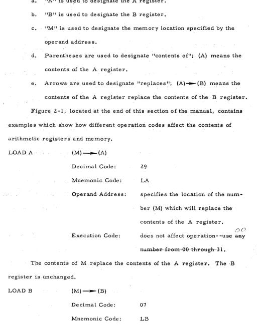
a. "A" is us~d to designate the A register.
b. "B" is used to designate the B register.
C. "Mil is used to designate the memory location specified by the
ope rand addre s s.
d. Pare nthe se s are us ed to de signate "contents of"; (A) means the
contents of the A register.
e. Arrows are used to d~signate "replaces "; (A) ... (B) means the
contents of the A register replace the contents of the B register.
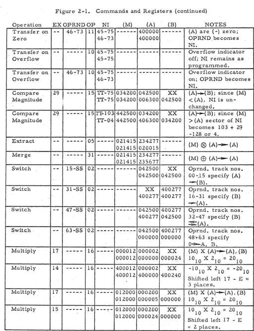
Figure 2-1, located at the end of this section of the manual~ contains
examples which show how different operation codes affect the contents of
arithmetic _-registers and memory.
LOAD· A (M)"':""'-(A)
Decimal Code:
Mnemonic Code:
Operand Address:
Execution Code:
29
LA
specifies the location of the
num-her (M) which will replace the
contents of the A register.
() c:)
doe s not affect operation- -use a,.ny
The contents of M replace the contents of the A re'gister. The·B
register is unchanged.
LOAD B (M) ---- (B)
Decimal Code: 07
Operand Address:
Execution Code:
Load B - - Continued
specifies the' location of the
num-ber (M) whi~h will replace the
contents of the B reglster.
C'JC)
doe s not affect operation- -use aBy
The contents of M rel?lace the contents of the B registe r. The A
register is unchanged.
LOAD A NEGATIVE - (M) - - - - (A)
Decimal Code: 21
Mnemonic Code: LN
Operand Addres s: ,specifies the location of the
number (M) which, with sign
changed, will replace the
con-tents of the A register.
Exe cut ion Code: does not affect operation--use (){J
The contents of M, with sign changed, replace the contents of the A
register. The B register is unchanged.
STORE A (A) ----(M)
Decimal Code: 30
Mnemonic Code: SA
Operand Address: spe cifie s the location M in which
the number in the A register will
Store A - - Continued
Execution Code:
0 0
doe s not affect operation- -use aay.
The contents of the A register replac~ the contents of M. The A
register and, the B registe r are unchanged.
STORE B (B)~(M)
Decimal Code:
Mnemonic Code:
Operand Address:
Execution Code:
20
SB
spe cifies the location M in which
the number in the B register will
be sto red.
OC_')
does not affect operation- -use afty.
The contents of the B register replace the contents of M. The A
register and theB register are unchanged.
ADD (A)
+
(M) ---(A)Decimal Code:
Mnemonic Code:
Ope rand Addre s s:
Execution Code:
25
A
specifies location of addend, (M).
DC:>
doe s not affect operation- -use a&y
The contents of M are added algebraically to the contents of the A
register; the signed sum rep lace s the previous contents of the A register.
If the sum is zero, the sign of the A register is unchanged. The B register
Add - - Continuecl
If the number of significant A-register. bits and/or the ~u~ber of
significant M bits is 17, an addi,tion command can re sult in a car ry bit that
cannot be accommodated in the
A
register. The carry bit, repre senting themost~significant bit of the sum, "overflows" the· A register ,and is lost.
Overflow does not halt the computer, but turns on the overflow indicator •
. Overflow can be detected by use of the transfer command: Transfer on
Overflow.
To obtain meaningful results from an Add instruction, it" is necessary
that the augend (A) and the' addend (M) have the same scale factor. ' Scaling
considerations are described in Section VIII.
(A) - (M) ~ (A).
Decimal Code:
Mnemonic Code:
Operand Address:
Execution Code:
24 .
s
specifies location of subtrahend,
(M).
t.,)C)
does not affect operation- -use &A¥
The contentis- of M are subtracted algeb.raically from the contents of
.
,
, .
the A register; the signed differenc~ replaces the previous. contents of the
A regist~r. If the difference is zero, the sign of the A·registe·r is unchanged.
Subtract - - Continued
Ove rflow can occur under the same conditions as specified, above for
the Add command. The minuend and subtrahend should have the same scale
factor, as 'discussed in Section VIII •.
5H1~T Decimal Code:
Mnemonic Code:
Ope rand. Addr e s s :
Execution Code:
01
SH
specifies the type of shift.
specifies number of places to be
shifted.
The track number in the operand address specifies the type of shift'
as follows:
Operand Track Address
Track 00 through 15
Track 16 through 31 .
Track.48 through 63
Type of Shift
shift (A) right; (B) unchanged.
shift (A) left; (B) unchanged.
shift (A) left; (B) left into A. ·
The execution code specifies the number of places to be ,shifted. Any
number from 00 through 31 can be used to obtain an instruction for shifting
from 00 through 31 places. The sign bits of th.e A and B registers are
un-changed by the Shift command.
The two types of shifts involving only the A register are open-ended,
so that bits shifted off either the right or the left end of the A 'register are
lost. When A is shifted right, the bit positions vacated at the Left end of the
A register are filled with zeros., When A is shifted left, the bit positions
Shift - - Continued
bits shifted off the left end of the A register tur,n on the overflow indicator.
(Overflow can be detected by usi~g the Transfer on Overflow command.)
When both the A register and B: register are shifted left, the two
registers are "coupled together so that the most-significant (I,7th) bit of the B
register mov~ s to the least-significant (1 st) bit position of the A register.
Bit positions vacated at the right end of ,the B register are fiUed with zeros.
Bits shifted off the left end of the A register are lO,st, but non-zero bits turn
'on the overflow indicator.
",.-.. ~--,,-~---... --.. -" ' . I
,\The
Sh~ft c~mmand m~y\also
be usedtomtil~iply ~~."
divideby/~owers
, /' \ ' ' , " ' / , , / 7 ,
of two. Hting regi\r
content8\~~ftone ,PJa:~e,i,~ eqUiVale~~ultiP1Ying
by two, and ifting ....
~igh~
one place "0.' -tvide s bytw~~\,,1 'F4te·~
u~~~;'~e.x-e'~~en,.:.-' \ , .:""" '--