This manual is published by the Univac Division of Sperry Rand Corporation in loose leaf format. This format provides a rapid and complete means of keeping recipients apprised of UNIVAC ® Systems developments. The infor-mation presented herein may not reflect the current status of the product. For the current status of the product, contact your local Univac Represent-ative.
The Univac Division will issue updating packages, utilizing primarily a page-for-page or unit replacement technique. Such issuance will provide notification of hardware changes and refinements. The Univac Division re-serves the right to make such additions, corrections, and/or deletions as, in the judgment of the Univac Division, are required by the development of its Systems.
UNIVAC is a registered trademark of Sperry Rand Corporation.
Other trademarks of Sperry Rand Corporation appearin g in the text of this pu blica tion are:
UNISERVO
UP-7546 UN IV AC 9200/9300
CENTRAL PROCESSOR AND PERIPHERALS
" " CONTENTS
\
1. I~TRODUCTION
1.1 THE UNIVAC 9000 SERIES
1.1. . Summary of Characteristics - U VAC 9200 System 1.1.2. Summary of Characteristics - N IVAC 9300 System
3.3. PUT/OUTPUT INTERFA 3.3 .. Multiplexer Channel 3 .. 2. Subchannels
:}I.3 3 Device Control Unit and Subch
!
~':3:4:
Buffer Control Word Location3.3.5. Additional Nonshared Subchannel
4. INPUT/OUTPUT UNITS
4.1. BASIC INPUT/OUTPUT UNITS - UNIVAC 9200 4 .. 1.1. Card Reader
4.1 .2. Card Punch 4 .. 1.3. Bar Printer
4,,2. OPTIONAL INPUT/OUTPUT UNITS - UNIVAC 9200 4,,2.1. UNIVAC 1001 Card Controller
4..3. BASIC INPUT/OUTPUT UNITS - UNIVAC 9300 4..3.1. Card Reader
4 . .3.2. ColiJmn Card Punch 4 .. 3.3. Bar Printer
4 .. 4. OPTIONAL INPUT/OUTPUT UNITS - UNIVAC 9300 4 .. 4.1. UNISERVO VI C Tape Units
4.4.2. Row Punch
Rev. 1 Contents
I
PAGE, 1 SECTION:CONTENTS
1
to4
1-1 to 1-3
1-1
1-2 1-32-1 to 2-2
2-1
2-1
2-1 2-23-1 to 3-8
3-1 3-4 3-4 3-4 3-5 3-6 3-7 3-7 3-7 3-8 3-8 3-8
4-1 to 4-17
2
UP-7546
I'
UNIVAC 9200/9300I
Contents~_~_~_~~NTRAL PROC~SSOR
AND
PE_R_I_P_H_E_R_A_L_S~~~~~~~~~._sE_c_T_,o_N_:~~~_P_A_G_E:~.~~~
5.1.
5.2.
I TRUCTION FORMAT5.2.1.'
X Instruction Format5.2.2.
S Instruction Format5.2.3.
S Instruction Forma5.2.4.
Di ct Addressing a d Indexing5.2.5.
Op ration Codes5.4.
BINAR5.4.1.
5.4.2.
5.4.3.
5.4.4.
5.4.5.
5.4.6.
5.6.
LOGICAL I TRUCTIONS5.6.1.
Logical In tructions in SI Format5.6.1.1.
Halt an roceed5.6.1.2.
Test U de Mask5.6.1.3.
5.6.1.4.
5.6.1.5.
5.Ei.1.6.
5.Ei.2.3.
5.6.2.4.
5.6.2.5.
5.6.2.6.
5.Ei.2.7.
5ol.
DEC MAL INSTRUCT ONS5.;'.1.
Pa k5.:' .2. U pack
5.?.3. C mpare Decimal
5).4.
A d Decimal5.;7.5.
S btract Decimal5.:'.6.
M ve with Offset5.1.7.
eroandAdd5.l.8.
ultiply Decimal 5.7 .9. ivide Decima IANCH OPERATIONS Bran ch on Cond iti on
5.B.2.
Branch and LinkUP-7546
6.
UNIVAC 9200/9300
CENTRAL PROCESSOR AND PERIPHERALS
6.1.
INPUT/OUTPUT CONTROL6.1.1.
Printer Control6.1.1.1.
Printer Instructions6.1.1.2.
Printer Buffer Control Word6.1.1.3.
Issue and Execute6.1.1.4.
Status Register6.1.1.5.
Interrupt Requests6.1.1.6.
Printer Status Bytes6.1.2.
Card Reader Control6.1.2.1.
Card Reader Instructions6.1.2.2.
Card Reader Buffer Control Word6.1.2.3.
Card Reader Status Bytes6.1.3.
_Card Punch Control6.1.3.1.
Card Punch Instructions6.1.3.2.
Card Punch Buffer Control Word6.1.3.3.
Card Punch Status Bytes6.1.3.4.
Read/Punch Error and Interrupt Conditions6.1.4.
Multiplexer Channel Control6.1.4.1.
Multiplexer Channel InstructionsEi.1.4.2.
Multiplexer Channel Buffer Control Word6.1.4.3.
Multiplexer Channel Status Byte6.1.4.4.
Condition Code6.1.4.5.
Alternate BCW Format6.1.4.5.1.
Data Direction ControlG.1.4.6.
Polling6.1.4.6.1.
Priority of Interrupt6.1.4.7.
Special Channel Instructions and Interrupts.6.1.4.7.1.
Operator Interrupt (Device Address8016 )
6.1.4.7.2.
One-Second Interrupt (Device Address9016 )
6.1.4.7.3.
L T Summary Interrupt (Device Address8816 )
6.1.4.7.4.
Summary of Special Channel Instructions6.1.4.8.
Channe I Checking6.1.4.8.1.
Interface Error Flip-Flop6.1.4.8.2.
Device Address Parity Error Flip-Flop6.1.4.8.3.
Parity Error Flip-Flop6.2.
DATA TRANSLATION6.2.1.
Card Code TranslationRev. 1
Contents
I
PAGEo 3UP 7546 Rev. 1 Contents 4
L
UNIVAC 9200/9300I
_~~_
CENTRALPROCESSORANDPERIP_H_E_R_A_L_S _ _
~
_ _ _ _ _
~.s_E_c_T_IO_N_:
_ _~~P_AG_E_:
_ _ _~
FIGURES
2-·l. UN IV AC 9200/9300 Systems Data Formats
3-·l. UNIVAC 9200/9300 Systems Basic Configuration Layout and Dimensions 3-·2. Equipment Range of UNIVAC 9200 System
3-·3. Equipment Range of the UNIVAC 9300 System 3--4. Organization of First 260 Bytes of Memory 4-·l. Card Reader Mechanism
4-·2. Card Punch Mechanism
4-·30 Card Punch Rate Versus Last Column Punched 4-·4. Basic Printing Configuration of Bar Printer 4-·5. Type Bar Removed from Printer
4-·6. Card Path Through UNIVAC 1001 Card Controller 4-.]. Tape Configuration and Data Conversion
4-·8. Card Path and Basic Mechanism in 200 CPM Row Punch 5-·l. UNIVAC 9200/9300 Systems Instruction Formats 5-·2. Operand Addressing
6-·l. Compressed Code 6-·2. Image Mode
T ABL.ES
4-l. Relationship of Internal Code to Printer Graphics 5-·l. Hexadecimal Symbols for 4-bit Binary Combinations 5-·2. Binary Values in Halfword Registers or Memory 5-·3. UNIVAC 9200/9300 System Instruction Summary
2-2 3-1 3-2 3-3 3-5 4-2 4-3 4-4 4-5 4-6 4-9 4-15 4-16 5-2 5-4 6-17 6-18
UP-7546 UNIVA\.- '1~UU/'l"UU
I
SECTION, 4
CENTRAL PROCESSOR AND PERIPHERALS
PAGE:
4. INPUT/OUTPUT UNITS
4.1. BASIC INPUT/OUTPUT UNITS - UNIVAC 9200
The basic UNIVAC 9200 System consists of the central processor with a bar printer, serial card reader, and serial card punch. The basic input/output units are integrated with the processor so that the system operates as one unit. The input/output units are considered to be extensions of the central processor.
4.1.1. Card Reader
CARD TYPE 80 column
CARD READING RATE 400 cpm
INPUT HOPPER CAPACITY 1200 cards OUTPUT STACKER CAPACITY 1500 cards
SPECIAL FEATURES 51- or 66- column short card feeds
UP-7546
CENTRAL
PRu~~~~;~;u~~~u~ERI_P_H_E_R_A_L_S
_ _~
_ _ _ _ _ ..I_s_EcT'oN:
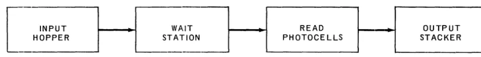
4The card reader has four functional stations: input hop,per, wait station, read photo-cells station, and output stacker. Cards move through the reader as indicated in the following diagram:
-READ OUTPU'
PHOTOCELLS STACKE
'
-[
INPUT
~_-+-I
WAITHOPPER STATION
, - - -
'----~-Figure 4-1. Card Reader Mechanism
The input hopper holds cards prior to feeding. Cards can be added to the input hopper card load without halting the feeding process. Cards are loaded into the hopper face down, 9 edge leading.
The wait station holds demand time to a minimum by serving as a retaining station for cards as they are fed from the input hopper prior to reading.
When a read command is received, cards are fed from the wait station into the read station. While one card is moving through the read station, another is moving from the input hopper to the wait station. The final step in the card reading process is to stack cards in the original sequence.
Data can be presented to the processor in compressed code translated from Hollerith card code or in image mode (see Section 6.2.1.).
I
3~
~~~~
__
~~~~:!~~~~~7~~U~U~/7~~~U~U~~~~=-
U" ..~~
AND PERIPHERALS__
JL __________
JI~s~EC~T~IO~N~:
. ___4 __
~_P_A_G_E:
_ _ _ _ _ _UP-7546
CENTRAL PROCESSOR
4.1..2. Card Punch
CARD PUNCH ING RATE
INPUT HOPPER CAPACITY OUTPUT STACKER CAPACITY REJECT STACKER CAPACITY SPECIAL FEATURES
75 to 200 cpm . nched h en entire card IS pu
75 cpm w .
14 or lower IS
200 cpm when co I. last co lumn punched 1200 cards
700 cards 700 cards
h read station Pre-punc
stacker select Program
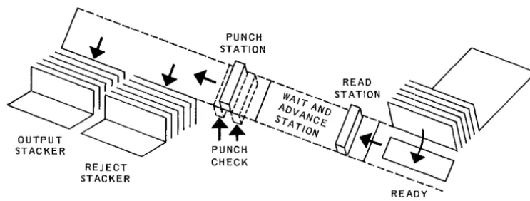
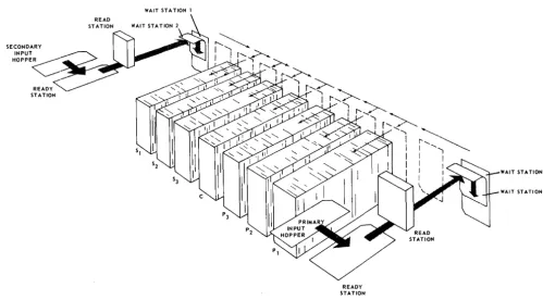
station, read station, ' of an input hopper, ready
, h mechanism consists, and output stackers. The basIc punc ' p u n c h station,
. d dvance station, walt an a
~
...
PUNCH_I
...
STATION" "
,~
. , "READ"::::~
~
~
... /
'~if"",
STATION~
~~"t~~'~~~l~71ifi3\
STACKER "REJECT READY
STACKER STATION
Card Punch Mechanism
UP-7546
- ••• - - -_ _ _ _ ...A.. _ _ •
CENTRAL PROCESSOR AND PERIPHERALS
I
SECTOON, 4 PAGE:80 76 72 68 64 60 LAST COLUMN PUNCHED 14 20 30 40 50 60 70 80 PUNCH SPEED (in cpm)
200 173 147 120 104 92 83 75
CARD CYCLE TIME (in milliseconds)
300 347 408 500 577 652 722 800
TIME AVAILABLE FOR PROCESSING (in milliseconds)
299 346 407 499 576 651 721 799
56 LAST COL" PUNCHED c 55 52 48 44 40 36 32 28 24 20 16 12
LAST COLUMN PUNCHED c 26
I ---=-...
1 1 I 1 I I I I I
I
----... ----+-~--.... ---+---... -.~--... ---+-... ...- ....-... --+---+---+-~-+--... -+-. --o+-~+--<---+---...-..>---+-. ...-~
70 81 87 93 99 105 III 117 123 129 135 141 147 1"53 159 165 171 177 183 189 195 200
RATE IN CARDS PER MINUTE
Figure 4-3. Card Punch Rate Versus Last Column Punched
The input hopper holds 1200 cards which are loaded face down with the nine edge leading. They are fed one at a time from the input hopper to the ready station, which holds one card at a time. The card then moves through the pre-punch read station if this particular option has been selected.
The wait station receives the card from the ready station or from the optional pre-punch read station and moves it to the pre-punch station, two columns at a time. With each advance, the card punch is capable of punching 24 holes.
Upon completion of the punching process, the cards are selected into one of two stackers, normal or select. The select stacker receives error cards automatically when the punch detects some punch-abnormal condition.
UP-7546 UJ"III" ~~ 7LUU/701UU
CENTRAL PROCESSOR AND PERIPHERALS
- - - - -_ _ _ _ 1..-_ _
I
SECTION, 4
_~~E'
4.1.3. Bar Printer
PRINTING METHOD PRINT POSITIONS
PRINT FONT
PRlNTING SPEED
PAPER SPEED PAPER SPACING
removable type bar
96
63 characters
250 LPM with 63-character font 300 LPM optional
25 inches per second (form skip speed) 6 I ines per inch
SPECIAL FEATURES variable speed printing with 48-character font 250 or 300 LPM for alphanumeric lines 500 or 600 LPM for numeric lines 120 print positions
132 print positions 8 lines per inch
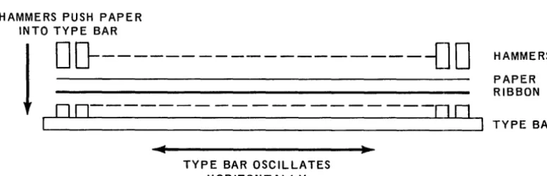
The bar printer uses an oscillating type bar. A simplified sketch of its operation is shown in Figure 4-4. Figure 4-5.is a photograph of the type bar removed from the chassis. The type bar oscillates horizontally in front of the paper. The character font is on the side of the bar facing the paper. Characters are printed when the print hammers strike the paper and push it against the selected characters.
HAMMERS PUSH PAPER INTO TYPE BAR
I
o
D---{]
0
DD---~
TYPE BAR OSCILLATES HORIZONTALLY
Figure 4-4. Basic Printing Configuration of Bar Printer
HAMMERS PAPER RIBBON
TYPE BAR
UP··7546 UNIVA\,. YLUU/Y"UU
CENT RAL PROCESSOR AN 0 PE RIPHERALS
PAGE:-
---
--
-
-Figure 4-5. Type Bar Removed from Printer
The motion of the bar, and thus its position relative to any given print hammer, is synchronized electronically. In effect, the printer knows which character is in front of a given hammer at any point in the print cycle.
Directions to the printer from the computer control the hammers to be actuated. The mechanism of the bar printer eliminates vertical smear or misalignment because the bar only moves in the horizontal plane. Also, the print bar can be changed in less than 60 seconds to insert different bar types.* The latter feature permits the prin ter to be optionally adapted for higher operating speeds by using a reduced character set.
Three knobs on the left side of the printer chassis provide manual control of paper positioning and alignment.
*Available on an RPQ basis.
UP-7546
I
UNIVAl,; '1:lUU/'1;iUU___
, ___
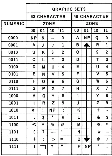
~~:ENTRAL PROCESSOR AND PERIPHERALSWhen a byte is being printed on a 63 or 48 character print bar, the two most signifi" cant bits of the byte are ignored; the relationship between graphics and bit code is shown in Table 4-1.
GRAPHIC SETS
63 CHARACTER 48 CHARACTER
NUMERIC ZONE ZONE
00 01 10 11 00 01 10 11
0000 NP &
-
0 A NP Q 0 0001 A J / 1 B..
~ R 1 0010 B K S 2 C S 2 0011 C L T 3 0 T 30100 0 M U 4 E U 4 0101 E N V 5 F V 5 0110 F 0 W 6 G W 6
0111 G P X 7 H X 7 1000 H Q y 8 I Y 8
1001 I R Z 9 J Z 9 1010 ¢ ! NP : K
+
1011 $ I
II L & $
1100
<
*
% @ M %*
1101 (r
-
IN II
-1110
+
:>
=
0 ~r @ /1111 I
-,
?"
P NP I,
Table 4-7. Relationship of Internal Code to Printer Graphics
4.2. OPTIONAL INPUT/OUTPUT UNITS - UNIVAC 9200
UP-'l546 UN IVA\" '1.lUU/'1.:5UU
I
I
CE
__
N_T_R_A_L __
P_R_O_C
__
E_S_SO
__
R_A
__
N_D __
P.E
__
R_I_P_H_E_R_A_L
__
S __
~~
__________
._S_ECT,_IO_N_:_4 _ _ _ _~~~PA,_G_E_:
_ _ _ _8 __ ___
-._---_._---4.2.1. UNIVAC 1001 Card Controller
The 9200 System with 1001 Card Controller
The UNIVAC 9200 Card Controller system can be provided in two configurations. In the basic configuration, the card reader is not used; card input is from the Card Con troller. In the other configu ration, the 400 cpm card reader is used with the Card Controller as a second source of card input. The UNIVAC 1001 can be used online or offline. It has a standard plugboard for online use. It has two card feeds, each of which can operate at 1,000 cpm making a total card feeding rate of 2,000
cpm.
Collating is the chief offline function of this unit. It has multipurpose capabilities which allow it to do card proving and editing, sorting, and statistical sorting. Computer processing functions, such as comparisons, addition, subtraction, and programmed multiplication are built into the Card Controller along with a core memory which has 256 storage positions. Seven large-capacity stacker outputs provide considerable selection versatility.
Some of the many functions which can be performed with the multiple system are as follows:
• Multifile input with merging and selection while processing.
• Advance file search of master files concurrent with detail card reading and previous record processing.
UP-7546
UNIVAC 9200/9300
4 9
CENTRAL PROCESSOR AND PERIPHERALS _ _ _ _ _ _ _ _ _ _ _ _ _ _ _ _ _ _ _ _ --L _ _ _ _ _ _ --'-_ _ _ _ _ _ _ SEC TION: ~ _ _ _ _ PAGE: ,,_~
SECONDARY
INPUT __
HOPPE~
<"-- READY',,-STA TlON
Figure 4-6 represents the path of card movement through the various stations of the Card Controller, as viewed from above. All card movement is under program control of the UNIVAC 9200 in conjunction with the standard plugboard in the UNIVAC 1001.
Four machine cycles are required for the movement of a card from input hopper to output stacker. The four cycles are as follows:
CYCLE 1 - The card is fed from the feed magazine to the ready station.
CYCLE 2 - The card is read. The card is moved from the ready station to the photocell assembly, for sensing, and then moves into one of the two wait stations.
CYCLE 3 - The card is held in the wait station.
CYCLE 4 - The card is ejected from the wait station and delivered to the selected stacker.
WAIT STA TION 1
READY STATION
Figure 4-6. Card Path through 1007 Card Controller
WAIT STATION 1
WAIT STATION 2
7C:Ah
I
UN IVAC 9200/9300_. __
UP-~
CENTRAL PROCESSOR AND PERIPHERALS SECTION:4
PAGE:4.3. BASIC I/O UNITS - UNIVAC 9300
The card reader, column card punch, and the bar printer are integrated with the UNIVAC 9300 central processor and are considered basic input/output units.
4.3.1. Card Reader
CHARACTERISTICS
CARD TY PE 80 column
CARD READING RATE 600 CPM
INPUT HOPPER CAPACITY 1200 cards OUTPUT STACKER CAPACITY 1500 cards
SPECIAL FEATU RES 51- or 66-column short card feeds
Cards move through the reader as shown in Figure 4-1.
UlP-7546 UN IV AC 9200/9300
CENTRAL PROCESSOR AND PERIPHERALS Rev. 1 4
J
11•• ,""" .~ E":"' _ _
SECTION:
4.3.2. Column Card Punch
CARD TY PE
CARD PUNCHING RATE
INPUT HOPPER CAPACITY OUTPUT STACKER CAPACITY REJECT STACKER CAPACITY
80 column 75 to 200 CPM
75 CPM when entire card is punched 200 CPM when column 14 or less is last column punched
1200 cards 700 cards 700 cards
---~r_---SPECIAL FEATURES
READ ONLY RATE
Prepunch read station (read/punch feature)
Program stacker se lect 200 CPM
UP-7546
~
UNIVAC 9200/9300I
4_ _ _
.
CENTRAL PRO,CESSOR AND
PER,_IP_H_E_R_A_L_S _ _
~_ _ _ _ _
~sEcT,oN:4.3.3. Bar Printer
CHARACTERISTICS
PRINTING METHOD removable type bar
PRINT POSITIONS 120
+
-PRINT FONT 63 characters
PRINTING SPEED 600 LPM wi th 63-char acter font
PAPER SPEED 25 Inches per second
+ ,
-LINES PER INCH
SPECIAL FEATURES
6
1200 LPM printing with 16-character font 132 print positions
8 I ines per inch
The following chart lists the complete 63-character and 16-character fonts.
FONT ALPHABETIC NUMERIC SPECIAL
63-Character A through
:z
0-9 - & . I t * $ @" % ' /
I
I ;q; : ?
<
= , (
+ > ) !
16-Character 0-9
- . *
$ , /12
UP-7546 UI'IIYA\.. 'I,LUU/'I"UU
CENTRAL PROCESSOR AND PERIPHERALS
Rev. 14.4. OPTIONAL INPUT/OUTPUT UNITS - UNIV AC 9300
A Row Punch, UNIVAC 1001 Card Controller, (see 4.2.1.) and UNISERVO VI C Magnetic Tape Units can be added to the basic UNIVAC 9300 System through the multiplexer channel.
4.4.1. UNISERVO VI C Tape Units
I
PAGEoThe tape oriented UNIVAC 9300 System uses UNISERVO VI C tape units connected to the system through the multiplexer channel.
UP-7546 UNIVA\.. '1.£UUI'I-'UU
I
(_: E_N_T_R_A_L_P_R_O_C_E_S_S_O_R_A_N_D_P_E_R_I
P_H_E_R_A_L_S_ ... _ _ _ _ _
... _
SEC TION:4
CHARACTERISTICS
-TAPE SPEED
DATA TRANSFER RAT E
RECORDING DENSITY INTERBLOCK GAP RECORDING FORMAT START-STOP TIME
-TAPE REVERSAL TIME REWIND TIME
NUMBER OF TAPE UNI PER SYSTEM
SPECIAL FEATURES
---
---TS
-
c---42.7 inches per second, for ward or backward 34,160 eight-bit bytes per second
800 bytes per inch for 9-tra ck tape 0.6 inch
9-tr ack N RZI
16.7 milliseconds nominal 21.7 milliseconds nominal 20 milliseconds or less
when read ing when writing
2400-foot tape reel in 180 s econds or less
---.---Minimum of two - one mast er and one slave with control unit
Maximum of eight with one control un it -two masters and six slaves
Maximum of 16 with two co ntrol units. Simu Itaneous read, wr ite, a nd compute with two control units
7-track N RZI tape format w ith 7-track feature on 9-track systems
7-track handlers may have r ecord ing
o
CPI den sit i e s 0 f 200, 5 56, 0 r 80Increased tape uti I ization 0 n 7-track tapes with data conversion
UP-7546 UNIVAC 9200/9300
h
4,
_ _ _ _
- '
_ _
,_C_E_N_T_R_A_L_P_R_O_C_E_S_S_O
... R_A_N_D_P_E_R_I_P_H_E_R_A_i.._S _ _
' - - _ _ _ _ _
SEC T ION: _ _ --'-_P _AG_E_:_A minimum of two tape units can be supplied with the UNIV AC 9300 System. These two tape units comprise a master/slave/control unit subsystem which is the minimum workable tape configuration. Each master tape unit can handle three slave units, and one control unit can handle up to eight tape units (two master and six slave units). Two groups of eight tape units, with one control unit for each group, is the maximum configuration.
To the standard 9-track subsystem (master, slave, and control) 7- or 9-track slave handlers can be added. A 9-track master unit will permit 7-track slaves to be used, but 9-track slaves cannot be attached to a 7-track master. Whenever a 7-track slave unit is added to a 9-track subsystem, the 7-track NRZI feature must be included.
An exclusive track NRZI tape subsystem (master, slave and control) to which 7-track handlers can be attached is also available.
The data conversion feature, when used with a subsystem having 7-track handlers, converts each data group of four 6-bit characters on tape into three 8-bit bytes for storage into memory. A reverse conversion takes place when data is transferred from memory to tape. The data conversion feature is available for both 7-track subsystems, and 9-track subsystems that have 7-track handlers. Figure 4-7 shows the tape con-figuration and the data conversion feature.
9-CHANNEL 7- or 9-CHANNEL
I
I
~~M
S====~rn-rn-rn-rn-m-rn
CONTROL UNIT
7-TRACK
I
FEATURE
I
" -_ _ _ --'-_ _ _ _ _ ...J
M
=
MASTER S=
SLAVE7-track feature required if 7-track tapes are used with 9-track control unit
9-track slaves cannot be attached to a 7-track master
9300
MEMORY
8-UNIT TAPE CONFIGURATION
7-TRACK TAPE UNIT
" -______________
~~
__~_8~~---~"_6_L
__~~
__6_~
8-BIT BYTES 6-BIT CHARACTERS
DATA CONVERSION
Figure 4-7. Tape Configuration and Data Conversion
UP-7546 UNIVAC 9200/9300
4
CENTRAL PROCESSOR AND PERIPHERALS PAGE:
4.4.2. Row Punch
~~ORMA_
ST AC KER
CHARACTERISTICS
CARD TYPE PUNCHED CARD PUNCHING SPEED INPUT HOPPER CAPACITY OUTPUT STACKER CAPACITY SELECT STACKER CAPACITY
t
-SPEC IAL FEATU RES
80 co lumn 200 CPM 1000 cards 1000 cards 1000 cards
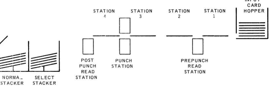
Program-controlled stacker select Automatic stacker select for error cards When an error occurs, the software causes the card in error to be repunched and located in its proper sequence in the fi Ie.
Prepunch read station for reading and punching along same card path
The basic card path and punch mechanism are shown in Figure 4-8.
SELECT STACKER
STATION STATION
3
D
---
---D ---D
POST PUNCH
READ ST ATION
PUNCH STATION
STATION
2
D
STATION
1
PREPUNCH READ STATION
Figure 4-8. Card Path and Basic Mechanism in 200 CPM Row Punch
INPUT CARD
~
UP-7546 UN IV AC 9200/9300 4
CENTRAL PROCESSOR AND PERIPHERALS PAGE:
4.4 .. 3. UNIVAC 1001 Card Controller
The UNIVAC 1001 Card Controller can be used online or offline,. Its chief offline function is collating. It has two card feeds each of which can operate at 1000 cpm, for a combined card feeding rate of 2000 cpm. Card collating operations are thus performed very rapidly, but the UNIVAC 1001 has multipurpose capabilities which also permit it to do card proving and editing, sorting, and statistical sorting. Computer processing functions such as comparison, addition, and subtraction are built into the UNIVAC 1001 along with a core memory that has 256 positions of storage. Seven large capacity stacker outputs provide considerable selection versatility.
Some of the multiple functions that can be performed with the combined UNIV AC
9300 and UNIVAC 1001 systems are as follows:
• Multifile input with merging and selection while processing.
• Advance file search of master fi1e(s) concurrent with detail card reading and previous record processing.
• Offline use of UNIVAC 1001 for collating, editing, sorting, and proving at the same time that the UNIVAC 9300 is computing and performing accounting machine operations.
Figure 4-6 represents the path of card movement through the various stat.lons of the Card Controller, as viewed from above. All card movement is under program control of the UNIVAC 9300 in conjunction with the standard plugboard in the UNIVAC 1001.
Four machine cycles are required for the movement of a card from input hopper to output stacker. The four cycles are as follows:
CYCLE 1 - The card is fed from the feed magazine to the ready station. CYCLE 2 - The card is read. The card is moved from the ready station to the
photocell assembly for sensing, and then moves into one of the two waH. stations.
CYCLE 3 - The card is held in the wait station.
CYCLE 4 - The card is ejected from the wait station and delivered to the selected stacker.
Cards are read in the same manner in the primary and secondary feeds. As a card leaves the ready station, it moves endwise under the photocell assembly where the holes punched in the card are sensed by a group of twelve photocells, one for each punching position in a column. Information is read a column at a time, beginning with column 1 and proceeding until the entire card has been sensed. Information read is then transferred to the UNIV AC 9300 for further processing.
UP-7546
Uf'IIIY"''''' 7"-YYI ,,"vv
CENTRAL PROCESSOR AND PERIPHERALS
SECTION: 6 PAGE:6. CONTROL_ WORDS
6. 1. INPUT/OUTPUT CONTROL
Various sets of memory locations are assigned to each input/output unit. Each set consists of four memory bytes, called a buffer control word, which is used for storing data storage addresses, character counts, and other details of each input/output function.
Input/output control requires the following software steps:
(1) Load the proper BCW with information required by the control unit, provided the unit is not busy.
(2) Issue an input/output instruction which specifies the device address and the function to be performed.
(3) Check the condition code setting to determine if the instruction was accepted. (4) Test the status of the device when the operation is completed (normally indicated
by the generation of an interrupt) to determine if the operation was successful.
Processing continues during the execution of all I/O instructions. If the H bit is set to one, all interrupts for the device are inhibited. The Test I/O instruction shoulld then be used to determine device status. An I/O interrupt can only be made at the end of a program instruction execution in the Processor Program State Control. At the end of each instruction execution, the peripheral interrupt request line is examined. If an interrupt request is present, interrupt is granted, control is shifted to the I/O Program State Control, and the device address and device status are stored in fixed locations in memory.
A BCW should not be altered during the execution of an input/output operation on the peripheral device to which it is assigned. To do so can cause unpredictable results.
6.1.1. Printer Control
The printer prints first and then advances paper. To allow the maximum amount of time to prepare the next line of data and to store the data in the specified print area, interrupt is generated before the paper advance operation is completed. Thus, the functions overlap since the next XIOF instruction can be issued before the. paper advance is completed for the last print instruction. If the interrupt were not gen-erated until after the paper advance, a bar cycle would be skipped after double spacing. Printing starts when the print bar is in either the extreme left or right! position. Printing then requires one complete cycle of bar movement, back and forth. An advance of as many as two lines can then be made without missing a print bar cycle.
UP-754b
CENTRAL PROCESSOR AND PERIPHERALS
I
PAGE.6.1.1.1. Printer Instructions
[
Print and control are the only valid print instructions. The bar selection modifies these codes and is effective only if the Bar Printer option has been included as part of the system. Print may be given with or without paper advance. Control is used for paper feeding without printing.
The Execute I/O instruction follows:
OP CODE A4
7 8
DA
00000011
15 16
where: X = 0 for a P rin t instruction X = 1 for a Control instruction B = 0 Standard 63-Character Bar B 1 Optional 48-Character Bar
Bl 0000 BNOH
19 20 23 24
N 1 Print Numeric if 48-Character Bar option is activated H 1 Inhibit interrupt
B must equal N (defined below).
N = 1 Print numeric if 16-character bar is installed H = 1 Inhibit interrupt
Note: In a control XIOF, Band N are not significant
OOXI
27 28
9200
1
9300On a system that has a printer with less than 132 print positions per line, data can be stored in the positions of the print image area for which there are no print hammers (locations 224 through 259, for a 96-position printer; or locations 248 through 259, for a 120-position prin ter), Such da ta is not altered by, nor does it affect, the operation of the printer.
:31
6.1.1. 2. Printer Buffer Control Word
[
The buffer control word for the printer contains the following data:
FC
OOOOLXXX
7 8
BA
where: BA = Base Address
STC
= Starting Code
CR = Code RegisterFC = Forms Control
J
16STC CR
31
UP-7546
V I ' I ... ""'" , . . V V , ,V''''..,CE_N_T_R_A_L
__
P_R_O_C
__
E_S_SO
__
R_A_N
__
D_P_E
__
R_IP_H
__
E_R_A_L
_S ____
~
__________
~I_~S~E~C~TI~O~N~:
_ _ 6 __~~P~A_GE~:
______~"
__ _ _CR, STC, and BA are under complete hardware control. If they are inadvertently changed by a program, a loss of printer control will probably result.
The forms control byte is loaded by the program once a TIO or an in terrupt de-termines it is permissible. The forms control byte is Rot changed by the execution of a printer function. The four bits which designate the desired forms action follow:
LXXX
o
0 0 0 Space 0 lineso
0 0 1 Space 1 lineo
0 1 0 Space 2 lines1 X X X Select any of 7 paper loop channel controls by matching holes in the paper loop to the 1 bits in the X positions.
There are two paper loop conventions: XXX
1 1 1 for home paper
o
0 1 for form overflowIf a hole combination is sought under paper loop control that is not punched on the tape, a runaway paper condition results.
6.1. 1. 3. Issue and Execute
"Issue" refers to the time that an XIOF is decoded by the processor and the command information is forwarded to the printer control. This is also the time at which the condition code (CC) is generated and made available to the program. "Execute" refers to the time that the printer controls respond to the command information forwarded by the processor. In some instances, "execute" may follow "issue" by a considerable period of time.
6.1.1.4. Status Register
The print controls contain a status register which stores the various error indi-cations until they are transferred to memory by a TIO or by an in terrupt request acceptance by the processor. When an XIOF is in progress, the setting of any bit in the status register will terminate the operation and generate an interrupt request.
The error conditions are divided into Type I and Type II. Type I errors set the status register directly when they occur. Type II error indications are stored in an intermediate error storage when they occur. The next time an XIOF is e x-ecuted they are transferred to the status register.
Type I errors are as follows: • Bar Check
• Memory Overload • Parity
u P-/ :'4b
CENTRAL PROCESSOR AND PERIPHERALS
I
SECTION, 6 PAGE:Type II errors are as follows:
• Paper Low • Forms Overflow • Paper Runaway
Bar Check occurs after an XIOF is executed, but before printing begins. Memory Overload occurs during printing.
Parity occurs after an XIOF is executed but before paper advances. Type II errors occur during paper advance.
Abnormal can occur any time.
When an offline error occurs, the status register is not set, but the reader appears to be busy to the processor. Any order in progress when the offline (OFF-LN) switch is depressed will be allowed to continue to completion.
6.1. 1. 5. Interrupt Requests
Interrupt requests occur at the following times:
• End of print before associated paper feed is started.
• Immediately following an accepted paper feed order before paper advancing has begun, unless a previously initiated paper feed order is in progress. In the latter case the interrupt is delayed un til the previously initiated paper feed order has been completed.
• Upon abortion of an order due to detection of paper low, forms overflow, or forms runaway as a result of a preceding order.
• Upon termination of an operation due to any other error condition.
6.1.1.6. Printer Status Bytes
The status byte (in location 66) contains information pertaining to the result of the last issued order or the next to last issued. order_ The status indications are as follows:
All zeros No indicators set; function performed as specified.
Bit 7 set to 1 Paper Low* as a result of paper spacing. Until the paper condition is corrected, this indicator will occur for each XIOF. Paper low will be indicated when the bottom edge of the form is 15 1/3" ± 1/3" from print line.
Bit 6 set to 1 Form overflow*. 001 sensed at paper loop station during single or double spacing. Form overflow is set even if spacing does not stop on the 001 channel punch. Passing over the punch is sufficient.
Bit 5 set to 1 Interrupt request pending. This status bit is set only if the TIO function clears a pending interrupt before it is accepted. This status bit does not indicate an error.
Bit 4 set to 1 Instruction does not agree with bar switch setting.
UP-7546 UNIVA\.. Y",UU/Y-,UU
C:ENTRAL PROCESSOR AND PERIPHERALS
SECTION: 6 PAGE:Bit 3 set to 1 Data parity or control parity error on last XIOF instruction. Printer stops immediately.
Bit 2 set to 1 Memory overload occurred on last XIOF instruction. Printer stops immediately. Paper has not advanced.
Bit 1 set to 1 Paper Runaway*-forms control lost. Further orders will not be accepted without operator intervention, since the printer goes abnormal.
Bit 0 set to 1 Abnormal or not ready.
*These conditions are recognized following the normal interrupt request. There-fore, the previous function will be properly completed except in the case of paper runaway where paper has been spaced improperly. If another XIOF has been accepted, it will be aborted and an interrupt will be generated. If the next XIOF is not issued until after detection of the condition, the order will be accepted, then aborted and an interrupt request will be generated. Any error that happens before paper is advanced will void paper advancing.
6.1. 2. Card Reader Control
The card reader reads a card in either translate mode or in image mode.
6.1. 2.1. Card Reader Instructions
[
The Execute I/O instruction for the card reader has the following format:
OP CODE A4
where:
7 8
x
=
0X
1
H=
1DA 00000001
15 16
Read Translate Mode Read Image Mode Inhibit all interrupts
Bl 0000
19 20 23 24
:l
00H - : : - ]
27 28 31
-These two combinations of bits, in the direct Bl - Dl field or the indexed B 1 - D 1, are the only permissible combinations of reader XIOF instructions. Any other combination may cause an error.
6.1.. 2. 2. Card Reader Buffer Control Word
The buffer control word for the card reader contains the following data:
COL.
J
16
I I
BASE I ADDRESS
I
23124
UP-'l546
~
UNIVA~ Y~UU/Y;:5UUI
_.____
_CENTRAL PROCESSOR AND
P~RI_P_H_E_R_A_L_S
_ _ _ _ _ _ _ _ _
s_EcT,oN:6
l
PAGE,where: HTS = Hardware temporary storage reserved for the reader. This byte should not be loaded by the program.
Col. The number of columns to be read. This must always be 80. This count will be decremented to zero to signal the end of the operation.
Base Address
= The address of the most significant halfword (even numbered
address) of the card read area in memory. Upon completion of the operation, this address will be one greater than the address of the last byte into which information was read.6.1. 2.3. Card Reader Status Bytes
The status byte contains information pertaining to the result of the last issued order or the next to last issued order. Status indications are as follows: All zeros No indicators set, function performed as specified.
Bit 5 set to 1 Interrupt request pending. This status bit is set only if the TIO function clears a pending interrupt before it is accepted. This status bit does not indicate an error.
Bit 1 set to 1 Misfeed, not ready, hopper empty or stacker full; these conditions are sampled only at initiation time of the XIOF instruction. If any one of these conditions exist, the XIOF instruction will be rejected. A Tes t I/O ins truction will then s tore this indicator only if it
follows an XIOF instruction which was rejected because of one of these conditions.
Bit 0 set to 1 Stacker jam, control parity or photocell check; instruction mayor may not have been accepted and card may have been fed.
The error conditions are divided into Type I and Type II. Type I errors set bit
o
of the status register as soon as they occur. Type I errors indicate that the data read into memory in this card read may not be correct and should not be used by the program. Type II error indications are stored in intermediate error storage when they occur. When the next XIOF is executed,they will set bit 1 of the status register. Type II errors are delayed until a subsequent XIOF because the data read into memory during the card cycle in which they occurred is correct and can be used by the program.All error conditions must be cleared manually. All error indications except Control Parity Error can be reset by depressing the Reader CLEAR switch. The Control Parity Error indication can be cleared by depressing the processor CLEAR switch. In addition, the Hopper Empty-Stacker Full (HESF) indicator can be reset by depressing the OFF-LN switch. The HESF indicator can be cleared in this way without error even if the processor is running and issuing XIOF~ to the reader.
Offline does not set the status register but will make the reader appear busy to the processor. Any order in progress when OFF-LN is depressed will be allowed to continue to completion.
UP'-7S46
UNIVA(; 92UU/9;JUUI
J
C E "_T_R_A_L_P_R_O_C_E_S_S_O_R_A_N_D_P_E_R_I P_H_E_R_A_L_S _ _
... ______
...
s .. IE __ C_TI_O_NI _ _6_
~:
__ "
~
6.1.3. Card Punch Control
Th.e card punch discussed below will include the controls required for the card reader option that may be incorporated to form a card read/punch.
6.1.3.1. Card Punch Instructions
The Execute I/O instruction for the card punch and reader option has the follQwing format:
IP CODE A4
7 8
where: H 1
P
1
R
1
X=O
X
=
1S
=
1
DA 00000010
15
Inhibit all In terrupts Punch a card
Read a card
16
B1 000
19 20 23 24
Read and/or Punch a card in compressed mode Read and/or Punch a card in im age mode
::-r-::l
~~
Select Stacker. Effective only if the program stacker select feature is installed. Otherwise, this specification is ignored.
Either the R or P bit must be 1. All other bits shown as O's must be O's, or an error may result.
Feeding with no reading or punching can be done by specifying the punching of two blank columns.
The second punch stacker is an error stacker and is selected on punch errors. This stacker is program selectable. However, errors will always cause this stacker to be selected regardless of program choice. Stacker selection is given for the card in the punch wait station in the same instruction that causes it to be punched.
6.1.3.2. Card Punch Buffer Control Word
The buffer control word for the card punch contains the following data:
C
HTS COL. BASE: ADDRESS1
=:J
o
_________________
~7~8~ ________________________ ~1~5~1~6~ ____________________ ~2~3~;2~4~_______________ 31where: HTS = Hardware temporary storage reserved for the punch. This byte
should not be loaded by the program.
UP-7546
[
UNIVAC YlUU/YJUU
I
C E N T R ALP ROC E SSO R AN 0 P E R,_I_P_H_E_R_A_L_S
_ _
-'--_ _ _ _ _
-'-='
E C T I ON:6
1,_p_AG_E_: _ _
8 _
Base Address
=
The address of the most significant halfword (even numbered address) of the card punch area in memory. Upon completion of the operation, this address will be one greater than the address of the last byte that was punched.HTS
The buffer control word for the punch reader option contains the following data:
COL.
15 16
I
I I
BASE I ADDRESS
I
I
23124
where: HTS = Hardware temporary storage reserved for the reader. This byte
should not be loaded by the program.
]
Col. = The number of columns to be read. This must always be 80. At the end of a card operation this count will be decremented to zero.
Base Address The address of the most significant halfword (even numbered address) of the card read area in memory. Upon completion of the operation, this address will be one greater than the address of the last byte into which information was read.
6.1. 3. 3. Card Punch Status Bytes
The status byte contains information pertaining to the result of the last issued order or to the next-to last issued order. The status indications are as follows:
All zeros No indicators set; function perform ed as specified.
Bit 6 set to 1 Hopper empty or stacker full; when this status bit is set the last XIOF function was terminated before it was executed. To re-cover from this early termination, the XIOF order must be rein-itiated after the condition has been corrected.
Bit 5 set to 1 Interrupt request pending. This status bit is set only if the TIO function clears a pending interrupt before it is accepted. It does not indicate an error.
Bit 4 set to 1 Photocell check error; this is a check on the read photocells as well as possible indication of a card jam. This error indication will be registered by status bit at the end of an XIOF. The last XIOF function should be assumed in error.
Bit 3 set to 1 Data parity or control parity error; card, at read station or card at punch station may be in error. An immediate interrupt occurs upon recognition of error and the XIOF is terminated. The card passing through the punch station will automatically go to the error stacker. This status bit indicates that the last XIOF in-struction was probably terminated before completion.
UP·-7546 UN IV AC 9200/9300
CENTRAL PROCESSOR AND PERIPHERALS Rev. 1 SECTION: 6 PAGE:
Bit 0 set to 1 Stacker jam, punch entry or exit check, interlocks, and any other condition that may necessitate manual intervention.
6,1.3.4. Read/Punch Error and Interrupt Conditions
The Read/Punch status register stores the various error indications until they are transferred to main memory by a TIO, or by the acceptance of an interrupt request by the processor. If an XIOF is in progress (except punch check error), the setting of any bit in the status register will terminate the operation and generate an
interrupt request.
Error conditions are classified as Type I and Type II. Type I errors set the status register when they occur.
Type II errors are stored in intermediate storage. The next time an XIOF is executed, the status is transferred to the status register.
All error conditions must be cleared manually except "Data or Control Parity Error" and "Punch Check Error", whi ch will be reset by a TIO when a condition code of
01 is returned, or by the processor accepting an interrupt request. Although status is stored on all TIO instructions, it is recommended that the program examine the status bytes only when a condition code of 01 is received.
Note that Off-Line does not set the status register, but will make the Read/Punch appear busy to the processor. Any order in progress when Off-Line is depressed will be allowed to continue to completion.
6.1.4. Multiplexer Channel Control
Peripheral units attached to the processor by way of the multiplexer channel also have their own particular control requirements.
6.1.4.1. Multiplexer Channel Instructions
When Execute or Test I/O instructions are issued to devices other than the basic peripherals (Device Address 1, 2 or 3), the channel will attempt to execute the initial selection sequence or I/O command. The channel will reject the command
if the addressed device is offline or does not exist. This will produce condition code 3.
6.1.4.2. Multiplexer Channel Buffer Control Word
When a subchannel is used, the proper BCW must be loaded with the correct initial conditions before issuing an Execute I/O order to any subchannel. Each subchannel requires a four-byte buffer control word in the main memory. The buffer control words contain initial data counts and working data counts, data addresses, and control bits. Eleven buffer control words have been reserved for the multiplexer channel (memory locations 84-127 10). It may also use buffer control words allotted to basic I/O units if they are not present.
UP-7546
3
UNIVAC 920019300
CENTRAL PROCESSOR AND PERIPHERALS
Rev. 1 SECTION: 6BCOO i4
+
4NWhen a control unit initiates a sequence in order to request or present data or to present a status byte, the control unit presents a device address along with appropriate control signals. This address is placed in the multiplexer channel's device address register where it is used to determine the location of the proper buffer control word. The action taken by the channel depends upon the contents of this location. The normal BCW format follows:
13 15
BYTE COUNT 0 DATA ADDRESS
(13 BITS) (15 BITS)
BC01 BC10 BCll
64
+
4N+
1 64+
4N+
2 64+
4N+
3Basic Form at: WM'; 11 W = Data Direction Bit
W 1 for write (output) or "buffered" control operations W 0 for read (input) operations
M Addressing Mode Bit
M = 0 for forward addressing sequence.
M = 1 for backward addressing sequence. T = Termination Bit
If T = 1, no data will be transferred, the BCW will not be modified by the channel and the Terminate response will be given to data request.
.-The channel will set T
=
1 after the transfer of a byte of data causes the byte count to go to zero. The channel will not reset the T bit to O.Byte Count: This field is decremented by the channel whenever a byte of data is transferred. An initial count of zero gives a block length of 8192 bytes if T
=
O.A control unit may terminate an operation before the count becomes zero. Upon termination this field indicates the difference, if any, between the initial byte count and the number of bytes actually transferred.
Data Address: This field is fetched by the channel and used as the address for the current byte of data. The address is modified in the BCW under control of the M bit in preparation for the next byte. Upon termination this field indicates where the next byte would have gone to or come from had the operation continued.
The Wand M bits and the I/O command initiated via the subchannel must agree"
10
UP-7546 UNIVAC 9200/9300 Rev. 1 ~ 6 11
C_E_N_T_R_A_L_P_R_O_C_E_S_S_O_R_A_N_D_P_E_R_I_P_H_E_R_A_L_S _ _
""--_ _ _ _ _
5 EC T ION: _ _ .a....;..P.;.;..AG.;..;E;;.;.: _ _6.1.4.3. Multiplexer Channel Status Byte
At the time of initial selection during an Execute I/O or Test I/O instruction and also at the end of I/O operations, peripheral units present a status byte with the following format:
Bit 0 Attention 1 Status modifier 2 Control Unit end 3 Busy
4 Channel end 5 Device end 6 - Unit check 7 - Exception
The status byte is stored in a program specified location by a Test I/O in-struction. When the channel is allowed to interrupt the program, the status byte is stored in location 66 10 ,
6.1.4.4. Condition Code
When an Execute I/O or Test I/O Instruction is issued via the multiplexer channel, the result of the operation is summarized in the condition code placed in the applicable program state control area.
CC EXECUTE 1/0 TEST 1/0
00 Command Accepted. Device Available.
No Channel Error. No Channel Error. Status Byte equals Status Byte equals
OOOOXXOO. 00000000.
01 Command Rejected. Nonzero Status Stored No Channel Error. and cleared.
Status Byte equal s No Channel Error.
OX010000, or OOOOXXOO. Status Byte does not equal OXOXOOOO.
10 Device, Control Unit Device, Control Unit, or Channel busy. or Channel busy. Command Rejected. No Channel Error. No Channe I Error. Status Byte equals
Status Byte equals OX010000.
OX010000.
11 Device, Control Unit, or Device, Control Unit, or Channel not operational. Channel not operational. Select out* or Select out* or Channel-channe I-detected error. detected error.
• Select out is the si~nal that the multiplexer channel sends to all the pherlpheral devices to
decide which one is to be selected.
Note that the channel may be momentarily busy on rare occasions, having just committed itself to a Request In Sequence as the I/O instruction was being staticized.
-UP-7546 Rev. 1 6
J
UNIVAC 9200/9300I
~_. ____ .. _ __:ENTRAL PROCESSOR AND
PERIP,_H_E_R_A_L_S_--II....-_ _ _ _
...
s_E_cT,oN: PAGE:6.1.4.5. Alternate BCW Format
An alternate buffer control word format (L T BCW format) is provided so that the system can handle devices that transfer a continuous stream of data at relatively slow speeds, such as communications line terminals for remote inquiry stations and computer to computer transmissions. The main variation is the fixed length wraparound buffer addressing sequence which can be considered as a limited form of data chaining. Note that this operation is defined by program, not by any device characteristic. The L T BeW format is specified when the Wand M bits are both ones, which would specify "Write Backwards" in the normal format. The LT BCW format follows:
11 TB BCOO
Status
T
4 5 6 7 ,
K 0BCOI
DA T A ADDRESS
8 bits 7 bits
Fixed Variable
BClO BCll
T := Terminate Bit: If the terminate bit is a one, no data will be transferred, the Data Address will not be modified, and the multiplexer channel will give the Terminate response to Data Requests. The channel will set the T bit to a one when "wraparound error" occurs (see Buffer End Bit). The channel will not erase a T bit.
B = Buffer End Bit: When the address modification generates a carry from the 2 5 bit position of the Data Address (when the address is modified to an integral multiple of 64 10) the channel sets the B bit to one and generates an L T Summary Interrupt request. The B bit alerts the program that a 64-byte buffer segment has ended. The program is expected to reset the B bit to zero when that buffer segment is again ready for use by the channel. If the channel finds a B bit set to one in the BCW when the End of Buffer Segment occurs again, the multiplexer channel sets the T bit to one so that the data will not be overlaid. This is the "wraparound error" situation. The channel will not reset a B bit; it must be removed by the program.
Data Address: This field contains the address of the next data byte to be trans-ferred. The address modification in the L T format is always A -I- 1 ~ A (Mod 128). This sequence, with the B bit, gives the effect of alternating the use of two adjacent 64 byte buffer areas.
Status Field: If a device operating in the LT mode initiates a sequence to present s ta tus, bits 4 - 7 of the status byte are merged (OR function) into this field. If the CPU allows the interrupt, the entire status byte is also placed in the Interrupt Entry area and the L T Summary Interrupt Request is set. If the Interrupt is not allowed, the LT Summary Interrupt Request is reset.
K Field (Address trap): If a device operating in the L T mode attempts to present status, and bits 4 and 5 in the Status field of the BCW were previously both zero, the eight least significant bits of the Data Address are transferred to the K field. If either bit 4 or bit 5 in the BCW was previously a one, the transfer does not occur.
UP-7546 UNIVA\.. Y,",UU/Y,)UU
CENTRAL PROCESSOR AND PERIPHERALS
Rev. 1I
SECTION, 6 PAGE:6.1.4.5.1. Data Direction Control
No control bits for data direction are provided in the LT format. In this format, odd numbered devices are assumed to be executing input operations and even numbered devices are assumed to be executing output operations. The data direction is controlled by the least siginficant bit of the device address, which was transmitted at the beginning of the Control Unit Initiated sequence.
6.1..4.6. Polling
The multiplexer channel wi 11 probe the interface every few microseconds, if the following three conditions exist:
• A printer scan is not in progress.
• The multiplexer channe 1 is not involved in a previous ly initiated sequence. • The Central Processor has not staticized an I/O instruction.
Buffered devices, and any other devices that can wait indefinitely to transfer data, w ill not generate service req ues ts when attached to this channe 1. (This is a patch able option in all control units.) These devices can capture the interface when the channel polis, but cannot force the channel to poll and interrupt a print scan.
6.1.4.6.1. Priority of Interrupt
If a device, on entering the multiplexer channel, has an XIOF rejected because its acceptance would exceed Data Transfer memory capacity, the Data Late bit is set in the Device Status byte, and the Unit Check bit is set in the Multiplexer Channel Status byte. In the presence of this condition, peripheral equipment will take the following priority of processing, from high to low priority: card reader, card punch, multiplexer channel, and printer.
If the punch, channel, and printer were working and the reader came in causing a memory-overload-anticipated condition, the printer would interrupt first and possibly the multiplexer channel would then int errupt. If the reader then went off, the multiplexer channel would come in followed by the printer. No matter which of the four levels presents the signal that would cause memory overload, this priority of interrupt occurs.
6.1.4.7. Special Channel Instructions and Interrupts
Certain device addresses are recognized and/or generated by the multiplexer channel itself. These "dummy" device numbers provide for:
1. Operator Interrupt. 2. One-second Interrupt. 3. L T Summary Interrupt.
4. Diagnostic and self checking features.
UP-7546
J
UI'4IVA\.. 'ILUUI'I.lUUI
14,_"~,_._._,_
... ,_". ___________ C :E NT R ALP Re
C ESSe R AN 0 PER I P_H_E_R_A_L_S __ -'-_______ .L_s_Ec T,_iO_N_~
_ _ _ --t._P.A __ G_E_: _ _ _ _ _Device numbers with the binary format 100xxxxx are the "dummy" device addresses. These addresses are trapped by the channel on Execute I/O Function or Test I/O Status instructions. They are generated when certain interrupts occur and under some diagnos tic conditions.
These" s ubchanne Is" do not have BCW's except in special diagnos tic operations.
6.1.4.7.1. Operator Interrupt (Device Address 8016 )
When the Operator Request button is operated, the setting of the Data Entry switches is stored in location 510 and the Operator Interrupt Request bit is set. When interrupts are allowed, the multiplexer channel will interrupt the program and store 8016 in location 67 10 and OC 16 in location 661.0' Once the Operator Interrupt Request is set, further operator requests are inhibited and the Operator Request Indicator is off until the program issues a Release Operator Request command by an Execute I/O Function instruction. An Execute I/O Function instruction may also be used to inhibit Operator
Request. The Operator Interrupt may be reset by a Test I/O Status instruction. Channel Clear or Master Clear sets the Inhibit Operator Request bit to the inhibit state.
6.1.4.7.2. One-Second Interrupt (Device Address 90 16)
An instruction is provided to set a one-second delay which will cause an interrupt when it recovers. When the interrupt is allowed, 9016 will be stored in location 6710 and OC16 in loca tion 661. 0' This interrupt reques t may be cleared by Test I/O or by Master Clear or Channel Clear. The actual delay time is one-second ±50%. Addressing this device while the delay is set but not recovered will result in the 102 (busy) condition code and 1016 status on a TIO instruction.
6" 1.4.7.3. L T Summary Interrupt (Device Address 8816)
UP-7546 UNIYA\...
'7LVV/'7>JVV
C E, __ N_T_R_A_L_P_R_O_C_E_S_S_O_R_A_N_D_P_E_R_I_P_H_E_R_A_L_s_---I. _ _ _ _ _
--L..I.
':..:E.:.,C.;...T I __ ON __~_~~
_ _6,1.4,7 A, Summary of Special Channe 1 Ins tructions Hexadecimal
Device Address
80
80
80 88 88 88
90 90
XIOF
Function Code 13*
23*
00 (TIO) 13* 23* 00 (TIO) 13
00 (TIO)
Function
Inhibit Opera tor Req ues t and
extinguish Opera tor Req ues t Indica tOL Permit Operator Requests and light Operator Request Indicator,
Test and reset Operator Request biL Inhibit L T Summary Interrupts, Permit LT Summary Interrupts,
Test and Reset LT Summary Interrupts, Set one-second de lay,
Test and reset one-second InterrupL
*These instructions are executed without regard for the resulting condition code, unless a channel error occurs,
6,104.8. Channel Checking
The multiplexer channel has three error flip-flops, Whenever one of them is set, the Central Processor will come to a stop unless a "dummy" device address is involved or the maintenance switches (for use by the UNIVAC Field Engineer) are set to the Time Out Test (X10) mode,
When the channel detects an error, the following information is saved as an aid to the UNIVAC Field Engineer by being stored in the special status bytes (locations 29, 30, and 31):
• I/O interface conditions at the time the error occurred • Setting of the multiplexer channel flip-flops
• Contents of the multiplexer channel Device Address register
UP-7546 UNIVA~ '1~UU/'1JUU
CIENTRAL PROCESSOR AND PERIPHERALS
6.1.4.8.1. Interface Error Flip-Flop This flip-flop will be set if:
• More than one of the following Inbound Control lines are activated: Device In
Status In
Da ta Reques t Probe Return
PAGE:
• An Interface Sequence has been initiated and not completed within 70 micro seconds.
• A Control Unit has held a Ready In condition active for more than 500
milliseconds without transferring data or status (Burst Mode time check).
6.1.4 .8.2. Device Address Parity Error Flip-Flop
This flip-flop is set if even parity is detected when a control unit has
signaled the presence of a Device Address on the Input line. If this flip-flop is set the Parity Error flip-flop will also be set.
6.1.4.8.3. Parity Error Flip-Flop This flip-flop will be set if:
• Even parity is detected on Input Data, Status Bytes, or Device Addresses. • Even parity is detected when a SCW byte is brought in from memory. The
Central Processor Parity Error flip-flop will also be set.
• A Memory Addressing Error is generated by the channel. The Central Processor Address Error flip-flop will also be set.
Addressing errors are generated if:
The channel attempts to address a location beyond the capacity of the given system.
The channel attempts to transfer data to or from the privileged area and Initial Load is not set.
The channel attempts to write data into locations 128-25510 while the Print flip-flop is set.
UP-7546
I
UN IVAC 9200/9300____ , ____
~~ENTRAL PROCESSOR AND PERIPHERALS SECTION: 66.2. DATA TRANSLATION
There are 256 possible code combinations that can be represented by an 8-bi t byte of memory. Card code translation is to or from compressed code. This code must be translated to the internal code for processing and then retranslated to the compressed code for punching.
6.2 .. 1. Card Code Translation
Eighty-column cards can be read or punched in compressed code or image mode. In the case of compressed code, the hardware compression is to or from an 8-bit code in memory. Since this 8-bit code is not one of the internal processing codes, it requires program translation after a card is read into memory and it requires program retranslation to generate 8-bit code for punching. This hardware com-pression is shown in Figure 6-1.
ROW PUNCHED BITS
PUNCH 123
NONE 000
011
2 101
3 001
4 010
5 100
6 111
7 110
1 2 3 4 MEMORY BYTE
BIT POSITIONS
UP-7546
I
UNiVA\.. 'ILUU/'IJUU