Volume 2008, Article ID 738281,9pages doi:10.1155/2008/738281
Research Article
Graph-Based Channel Detection for Multitrack
Recording Channels
Jun Hu,1Tolga M. Duman,2and M. Fatih Erden3
1Qualcomm Inc., San Diego, CA 92121, USA
2Electrical Engineering Department, Ira A. Fulton School of Engineering, Arizona State University,
Tempe, AZ 85287-5706, USA
3Seagate Technology, Pittsburgh, PA 15222-4215, USA
Correspondence should be addressed to Tolga M. Duman,[email protected]
Received 26 March 2008; Accepted 28 November 2008
Recommended by Geert Leus
We propose a low complexity detection technique for multihead multitrack recording systems. By exploiting sparseness of two-dimensional partial response (PR) channels, we develop an algorithm which performs belief propagation (BP) over corresponding factor graphs. We consider the BP-based detector not only for partial response channels but also for more practical conventional media and bit-patterned media storage systems, with and without media noise. Compared to the maximum likelihood detector which has a prohibitively high complexity that is exponential with both the number of tracks and the number of intersymbol interference (ISI) taps, the proposed detector has a much lower complexity and a fast parallel structure. For the multitrack recording systems with PR equalization, the price is a small performance penalty (less than one dB if the intertrack interference (ITI) is not too high). Furthermore, since the algorithm is soft-input soft-output in nature, turbo equalization can be employed if there is an outer code. We show that a few turbo equalization iterations can provide significant performance improvement even when the ITI level is high.
Copyright © 2008 Jun Hu et al. This is an open access article distributed under the Creative Commons Attribution License, which permits unrestricted use, distribution, and reproduction in any medium, provided the original work is properly cited.
1. INTRODUCTION
In the past few years, magnetic recording systems have seen great breakthroughs both in fabrication techniques and in the development of signal processing algorithms. As recording densities increase, data recovery processes become more complicated. Due to the reduction of island separations in both along-track and cross-track directions, the amount of intersymbol interference (ISI) and intertrack interference (ITI) increases rapidly which potentially results in significant degradations in the performance of traditional systems. In addition, the implementation of timing and gain control becomes more difficult. Multihead multitrack recording represents a promising direction to improve detection capa-bilities with increased recording densities. Such methods not only offer a better performance by suppressing the ITI and ISI efficiently but also increase efficiency in control infor-mation overhead. So far, multihead multitrack recording has been proposed in the context of conventional media record-ing systems, and several studies have been reported [1–11].
Due to the “superparamagnetic effect,” conventional media storage systems have approached their maximum achievable recording densities. To further extend this storage density limit, several new technologies have been proposed recently, among which patterned media recording [12–19] has attracted a significant interest due to its potential to achieve ultrahigh recording densities. In this paper, we deal with general multihead multitrack recording systems, however, we also pay special attention to their use for patterned media recording systems.
solve this problem. For example, detection can be performed iteratively on rows and columns of the 2D ISI channel [20], or as an alternative, one can consider a simplified trellis, either by reducing the number of states [8], or by reducing the number of branches per state [10,11].
In this paper, instead of using a multidimensional Viterbi algorithm, we consider the detection problem from a different perspective and develop an efficient algorithm for multitrack systems with an acceptable computational complexity. To this end, we propose to use belief propagation (BP) [21, 22] to perform inference on factor graphs of multihead multitrack recording channels. This idea has been recently applied to generalized 2D ISI channels and it is shown that the detection performance is poor for very loopy channel conditions [23]. Meanwhile, an enhanced BP detector is proposed to achieve near optimal performance with some complexity increase. Here, we note that although the proposed detector is not optimal in general, it suffers from only a small performance penalty at low to medium ITI levels for multitrack recording with PR equalization. At the same time, due to the inherent sparseness of the channel, the detector maintains a low complexity and a fast parallel structure. It is applicable to both conventional and bit-patterned media storage systems. In our development, instead of working on 2D multitrack recording channels directly, we consider channel detection over an equivalent 1D channel. Furthermore, since the detector is soft-input soft-output in nature, we also consider turbo equalization to further improve the data recovery performance, which has also been considered in [24,25] for 2D ISI channels with different detection algorithms.
The rest of the paper is organized as follows. InSection 2, we introduce the system model. In Section 3, we discuss the equivalent 1D channel model and develop the BP-based detection algorithm. Performance evaluations for different channels are illustrated and discussed inSection 4. Finally, some remarks are presented in Section 5 to conclude the paper.
2. SYSTEM MODEL
We consider a multihead multitrack recording system with an array of NR heads flying over NT adjacent tracks. For
each group of NT tracks, there are two guard bands (no
information written) on each side. The signal read by therth head is given by
yr(t)= NT
s=1 +∞
i=−∞
xisgr,s(t−iT) +nr(t), 1≤r≤NR, (1)
wherexi
sis theith bit stored on thesth track with the value
{+1/−1}, gr,s(t) is the channel response incorporating both
ISI and ITI (from thesth track to therth head), and the noise
nr(t) is assumed to be additive white Gaussian with a mean
of zero and a power spectral density of N0/2. To simplify the description of the algorithm, we assume that interference in the cross-track direction is limited to two adjacent tracks with an interference factor ofη[6]. Therefore, the readback
signal is modeled as
yr(t)=
+1
j=−1 +∞
i=−∞
xi
r−jη|j|h(t−iT) +nr(t), (2)
where h(t) is the channel response in the along-track direction. For bit-patterned media, the readback pulseh(t) can be calculated using the reciprocity principle [14, 17]. For conventional media, we consider longitudinal recording channel as an example where the transition response is usually modeled as a Lorentzian pulse, that is,
p(t)= 1 1 + (2t/PW50)2
. (3)
Recording density is defined as D = PW50/T, and the channel response is given by h(t) = p(t)− p(t−T). We consider the case of NT = N, NR = N + 2, where two
extra heads are centered over the two-guard bands. For other choices of (NT,NR), our algorithm is still applicable
in a similar fashion. The signal-to-noise ratio is defined as SNR = Eh/(N0/2), whereEh =
+∞
−∞h2(t)dtis the energy of the channel response.
In magnetic recording systems, in addition to the additive white Gaussian noise, another important source of noise is jitter. In conventional media storage systems, dominant media noise sources include position fluctuations and pulse width variations. When they are incorporated into the channel model, the transition response in the kth time interval is given by
pk(t)=
1
1 + [2(t−Δtk)/(PW50+Δwk)]2
, (4)
whereΔtk andΔwk represent the position jitter and width
jitter for thekth transition. In our model, we assume that they are truncated Gaussian random variables with variances
σt2 and σw2, respectively. Δtk is limited to [−T/2,T/2] and Δwk must be larger than −PW50. In patterned media storage systems, although transition noise accompanied with conventional film media is eliminated, other forms of media noise arise [13,15,17,19]. For example, position jitter, bit size jitter, and magnetization jitter are three major types of media noise. Similarly to the case of the conventional media, we can also model them as truncated Gaussian random variables (e.g., in this paper, we will give an example considering the position jitter withΔtk∈[−T/2,T/2]).
At the receiver, readback signals are passed through a front-end low-pass filter, sampled at the symbol rate and then equalized to a certain partial response target using a linear equalizer under the MMSE criterion. The original data is then recovered from the output of the equalizer using a suitable detection algorithm, which is the main focus of this paper.
3. MULTIHEAD MULTITRACK DETECTION
3.1. Joint detection
The optimal solution to the problem is a full ML-type or MAP-type detector using either the Viterbi algorithm or BCJR algorithm, respectively, both of which are based on the ISI channel trellis. However, since we need to consider simultaneous detection of multiple tracks, the trellis for the 2D ISI channel is much more complicated than the single-track case. Computational complexity of the detector increases exponentially with both the number of tracks
N and the target length LS. Even for moderate values of N andLS, complexity becomes quite prohibitive, thus the
optimal algorithms are not practical. For example, for a single-track channel with a partial response target of order
LS = 3, the trellis is defined by 2LS−1 = 4 states each
with 2 branches, which may be reasonable in complexity for practical implementation. However, when we consider a multitrack channel withN=5 tracks and the same ISI length
LS = 3, the number of states becomes 2N(LS−1) = 1024 and
the number of branches for each state transition is 2N =32.
To efficiently perform the joint detection, we need to find reduced-complexity alternatives while maintaining a near-ML performance. With this motivation, several pre-vious papers have either worked with simplified trellises [8, 11], or worked on rows and columns iteratively [20]. The proposed approaches provide good tradeoffs between complexity and performance. In this work, we consider the problem from a different perspective and work with a factor graph representation of the channel and propose a BP-based detector. A major advantage of the proposed detector is that its complexity will not increase with the number of tracks as we will see in the following sections.
Belief propagation algorithm is an efficient method to solve many probabilistic inference problems over graphs. For example, it has been successfully applied to decoding of low-density parity-check codes [26]. Although it is not optimal when there are cycles in the graph, it is shown empirically that the algorithm gives good results for a wide range of cases. Recently, it has also been exploited in data recovery for single-track recording channels [27,28]. It has been proven that the performance of the BP-based detector is the same as that of ML/MAP-based detectors when there are no cycles, and it approaches the optimal ML/MAP performance when there are no short cycles. In [29], the authors still consider single-track recording channels, but extend the use of BP detection to the case of correlated noise. For general 2D ISI channels, [23] proposes to use a generalized BP algorithm for channels with loopy conditions. Here, we consider the use of BP algorithm for data recovery over multihead multitrack recording channels by considering an equivalent 1D channel model as described next.
3.2. Equivalent channel model
The 2D ISI channel can be represented as a factor graph. This concept can be described using different perspectives. To give a clear and simple picture, we follow the approach of [11], where the 2D ISI channel is viewed as a time-varying 1D channel.
Guard band
0 0 · · · 0 0 0 0 · · · x1 x9 · · · xk−18 xk−10 xk−2 · · ·
x2 x10 · · · −η 0 η · · ·
x3 x11 · · · −1 0 1 · · ·
x4 x12 · · · −η 0 η · · ·
x5 x13 · · · xk−14 xk−6 xk+2 · · ·
x6 x14 · · · xk−13 xk−5 xk+3 · · ·
0 0 · · ·0 0 0 0 · · · Guard band
Figure1: Channel coefficients of the equivalent 1D time-varying channel model for 2PR4 target at thekth time instant,N=6.
Let us first look at the timing-varying 1D channel model. Consider the classical PR4 target, for which the corresponding 2D partial response target (denoted as 2PR4 channel) is given by
H2PR4=[η, 1,η]T[1, 0,−1]=
⎡ ⎢ ⎣
η 0 −η
1 0 −1
η 0 −η
⎤ ⎥
⎦. (5)
The time-varying 1D channel corresponding to this 2D partial response channel is illustrated inFigure 1.
As a function of delayD, the target can be represented in causal form as in [11]
H21PR4(D)=η+D+ηD2−ηD2N+4−D2N+5−ηD2N+6, (6)
or, in noncausal form, as in our model, by
H2
2PR4(D)=ηD−1+ 1 +ηD−ηD2N+3−D2N+4−ηD2N+5. (7)
As we can see, the advantage of this channel model over the 2D model is reduction of the number of branches for each state (from 2N to 2). However, the number of states
is still very large, that is, 22N+2. To solve this problem, the authors in [11] use theM-algorithm which is a particular tree search algorithm for detection.
3.3. New approach—BP detection
Factor node
Bit node
Time y0 y1 y2 · · · y2N+4 y2N+5 · · ·
−η
−1 −η η 1 η
x0 x1 x2 · · · x2N+4 x2N+5 x2N+6 · · ·
Figure2: Factor graph of H2PR4 channel model.
3.3.1. Factor graph
Instead of using a trellis, the time-varying 1D channel can also be characterized using a factor graph as shown in
Figure 2. Each factor node represents an output signal and
each bit node denotes a written bit to be recovered. The factor nodes are connected to the bit nodes through the channel model given in (7). We note that, the factor node degree and the bit node degree are both equal to 6 for the 2PR4 target.
3.3.2. Detection algorithm
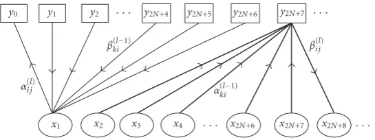
Based on the factor graph representation, we can use the belief propagation algorithm to perform data recovery as illustrated inFigure 3(which are similar to the algorithms employed in [27,28]).α(i jl)denotes the message propagated
from bit nodeito the neighboring factor node j at thelth iteration andβ(i jl)denotes the message sent from factor nodei
to the neighboring bit node jat thelth iteration. We will use log domain representations to express all the messages passed along the edges.
At each factor nodei, the a posteriori LLR is generated for each connected bit node j based on the received signal, ISI channel constraint, and extrinsic information from other connected bit nodes. It is given by
β(i jl)=log
P(xj=+1|yi) P(xj= −1|yi)
=log
Bi:xj=+1p(yi|Bi∼xj,xj=+1)P(B i
∼xj)
Bi:xj=−1p(yi|Bi∼x
j,xj= −1)P(B i
∼xj)
, (8)
where we useBi = (x
i1,. . .,xiF) to denote all the bit nodes
that are connected to factor nodeiandBi
∼xj to denote the
same set of bit nodes excluding bit node j. Fis the degree of the factor node. All possible choices of Bi are divided
into two sets and separately included in two summations, depending on whether xj equals +1 or −1. Given the ISI
channel constraint, p(yi |Bi) can be easily expressed using
Gaussian probability density function. If we assume that all the incoming messages are independent (this is true for a cycle-free graph and only approximately valid when the graph has cycles), the second term can be decomposed into
(supposej=in)
PBi
∼xj
=Pxi1,. . .,xin−1,xin+1,. . .,xiF
=Pxi1
· · ·Pxin−1
Pxin+1
· · ·PxiF
, (9)
where
Pxk
= ⎧ ⎪ ⎪ ⎪ ⎪ ⎪ ⎨ ⎪ ⎪ ⎪ ⎪ ⎪ ⎩
exp−α(kil−1)
1 + exp−α(kil−1)
, xk= −1,
1 1 + exp−α(kil−1)
, xk=+1.
(10)
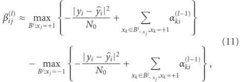
To further simplify the computation, we may employ the “max-log” approximation, that is, log(ex+ey)≈max(x,y).
Thus, the update message is given by
βi j(l)≈ max Bi:x
j=+1
⎧ ⎪ ⎨ ⎪ ⎩−
|yi−yi|2 N0
+
xk∈Bi∼x j,xk=+1 α(kil−1)
⎫ ⎪ ⎬ ⎪ ⎭ − max
Bi:x j=−1
⎧ ⎪ ⎨ ⎪ ⎩−
|yi−yi|2 N0
+
xk∈Bi∼x j,xk=+1 α(kil−1)
⎫ ⎪ ⎬ ⎪ ⎭, (11)
whereyi=ηxi+1+xi+ηxi−1−ηxi−2N−3−xi−2N−4−ηxi−2N−5is the noiseless channel output corresponding to each possible choice ofBi.
At each bit nodei, by exploiting the a priori information from outside the detector and messages obtained from connected factor nodes, extrinsic information for factor nodejis calculated as
α(i jl)= iV
k=i1,k /=j
βki(l−1)+θi, (12)
whereV denotes the bit node degree (the number of factor nodes that are connected to the bit node), andθiis the apriori
information aboutxi.
After several predetermined iterations (L), the final soft output is computed as
L(xi)= iV
k=i1
β(kiL)+θi. (13)
This soft information can be used either for making instant decisions if there is no outer code, or it can be considered as the soft input for the outer decoder. For the latter, since our detector is a soft-input soft-output module, we can also apply turbo processing techniques to the whole system. In that scenario, extrinsic information from the outer decoder is treated as the a priori informationθ.
3.4. Computational complexity
y0 y1 y2 · · · y2N+4 y2N+5 y2N+6 y2N+7 · · ·
α(i jl)
βki(l−1)
α(kil−1)
β(i jl)
x1 x2 x3 x4 · · · x2N+6 x2N+7 x2N+8 · · ·
Figure3: Diagram of the message-passing process.
updates and the final output are given by (11)–(13). At each factor node, we can observe from (11) that |yi −
yi|2/N0 only needs to be computed at the first iteration and will not change in the following iterations. To calculate this term, for each Bi, 2 multiplications (one for the
square operation and one for the division of N0) and F additions (to calculate yi− yi) are needed. Here, F is the
factor node degree, and is also the number of nonzero PR channel taps. Since there are 2F−1 possible choices of B
i
when xj = +1/ −1, the total number of operations to
compute|yi−yi|2/N0 is approximately F2F additions and 2F+1multiplications. In addition to these operations, for the first and rest of the iterations,F2F additions (with updated αki) and 2F comparisons are necessary. At each bit node,
the message updates are relatively simple and only additions are needed (about V additions per iteration). Therefore, we can see that the total computational complexity for the BP-based detector is mainly determined by the complexity at the factor nodes, and it is linear with the number of iterations and exponential with the number of nonzero taps.
Compared with the ML/MAP detector, the complex-ity of the proposed algorithm is greatly reduced and it becomes applicable for practical systems. For example, let us consider a PR target with the length of ISI span and ITI span selected to be LS and LT, respectively.
The number of tracks is N, that is, we want to decode
N data sequences jointly. For the 2D Viterbi decoder, numbers of multiplications/additions/comparisons per bit are all approximately 2NLS. For the 1D Viterbi decoder
(corresponding to the 1D equivalent channel model intro-duced in Section 3.2), they are approximately 2N(LS−1)+LT.
Considering the reduced complexity versions of the Viterbi algorithm [8], for example, for theM-algorithm, we need 2NS number of multiplications/additions and an extra
sorting complexity which is approximately linear with
S (S is the number of surviving paths). Compared to the BP-based detector, we can see that our detector is more favorable when N becomes larger. We also note that the structure of the BP algorithm makes it possible to employ parallel implementation, which will potentially make the detection faster. Therefore, the proposed BP-based detector provides us with a promising low-complexity solution for multitrack recording channels with PR equaliza-tion.
4. EXAMPLES
Let us present several performance evaluation results for different channel models and different parameters using the proposed detector. We note that for other suboptimal approaches [8,11,20, 23], there exists a tradeoffbetween complexity and performance, and an easy comparison is generally hard to achieve. Therefore, we will only compare the error rate performance of the proposed detector with that of the optimal full-complexity ML detector. A rough com-parison with other approaches can be obtained by observing the corresponding differences with the performance of the optimal detector.
First, let us look at the system performance with varying number of iterationsL. We consider a 2D partial response (2PR4) channel with N = 8 and η = 0.1. As shown in
Figure 4, the system performance is closely related to the
number of iterations. If L is too small, the performance is severely degraded. On the other hand, ifL is too large, additional performance improvement with further iterations is only marginal. The reason is as follows. With small L, each node cannot obtain enough extrinsic information from other nodes to provide an accurate estimation of actual data. With large L, exchanged messages will either approach the true LLR information if the factor graph is cycle-free, or become correlated with each other if there are cycles. For either case, the improvement that can be provided is limited. Since complexity increases linearly withL, we should choose it appropriately. In the following discussions, we will pick
L=10.
We next compare the performance of the BP-based detector with that of the full-complexity ML detector in
Figure 5. In this example, we chooseN =5. It is clear that,
10−5
10−4
10−3
10−2
10−1
100
Bi
t
er
ror
ra
te
5 6 7 8 9 10 11
SNR (dB) L=1
L=2 L=3 L=4 L=5
L=6 L=7 L=8 L=9 L=10 Figure4: Effect of number of iterations.
10−5
10−4
10−3
10−2
10−1
100
Bi
t
er
ror
ra
te
6 8 10 12 14 16 18
SNR (dB) η=0, BP
η=0.1, BP η=0.2, BP η=0.5, BP
η=0, ML η=0.1, ML η=0.2, ML η=0.5, ML Figure5: Performance over 2PR4 channel.
of short cycles starts to degrade the system performance considerably. Therefore, the proposed BP-based detector is suitable for channels with low to medium ITI levels. For high ITI levels or channel factor graphs with worse loopy conditions, an enhanced BP detector needs to be constructed, for example, one can tradeoffcomplexity with performance as done in [23].
In practical magnetic recording channels, because of front-end filtering and equalization, noise becomes colored. To assess the performance of the proposed algorithm for this scenario, we apply the BP detection algorithm to a more practical storage system. We consider examples for two dif-ferent systems: conventional media and bit-patterned media. For conventional media, we give an example based on the Lorentzian channel model. With a signal-to-noise
10−4
10−3
10−2
10−1
100
Bi
t
er
ror
ra
te
1.5 2 2.5 3
Recording density (D) η=0
η=0.1 η=0.2
η=0.3 η=0.4 η=0.5
Figure 6: Performance for conventional media storage system (Lorentzian channel).
ratio of 15 dB, system performance with different recording densities and differentηis evaluated inFigure 6. It is clear that degradation due to ITI is much more severe at low recording densities.
To give an example with patterned media, we choose the following parameters as an example. The read pole head length and width are selected as 4 nm and 20 nm, respectively, and the shield-to-shield gap is chosen to be 18 nm. The head-medium spacing and medium thickness are both fixed at 10 nm, and the islands are assumed to be square with a side length of 15 nm. The bit pitch distance
Ta is fixed at 30 nm and the track pitch distance Tb is
varied depending on the recording density. Several results are shown inFigure 7. Again, we observe that the performance of the BP-based detector is very close to that of the full-complexity ML detector for largeTb (low ITI levels) and is
degraded for smallTb(high ITI levels).
We also consider the BP detection over magnetic record-ing channels with media noise. We again evaluate two different media. InFigure 8, we investigate the Lorentzian channel when there exist different levels of position jitter and pulse width jitter. It is clear from the results that the detection performance is more sensitive to the position jitter. With the same level of position jitter, error rate curves due to different width jitter almost overlap with each other. However, when the position jitter increases, performance is degraded greatly. We note that in this case, our detector can be further improved by performing noise prediction [29]. However, we do not pursue this topic in this paper. Similarly, we evaluate patterned media recording channels with position jitter in Figure 9as an example, and observe similar behavior.
10−5
10−4
10−3
10−2
10−1
100
Bi
t
er
ror
ra
te
10 12 14 16 18 20 22 24 26 28 30 SNR (dB)
Tb=30 nm, ML Tb=25 nm, ML Tb=22.5 nm, ML Tb=20 nm, ML Tb=17.5 nm, ML
Tb=30 nm, BP Tb=25 nm, BP Tb=22.5 nm, BP Tb=20 nm, BP Tb=17.5 nm, BP Figure 7: Performance for bit-patterned media storage system (perpendicular recording).
10−5
10−4
10−3
10−2
10−1
Bi
t
er
ror
ra
te
10 12 14 16 18 20 22 24 26 28 30 SNR (dB)
σt=0,σw=0 σt=0,σw=0.05T σt=0,σw=0.1T σt=0.05T,σw=0 σt=0.05T,σw=0.05T
σt=0.05T,σw=0.1T σt=0.1T,σw=0 σt=0.1T,σw=0.05T σt=0.1T,σw=0.1T
Figure8: Performance for conventional media storage system with media noise levels.
For the first example, we consider an outer turbo code where two encoders with the same generator (23/31)octal are parallel concatenated using a random interleaver with length 10 000. The code rate is fixed at 8/9 and the number of turbo decoding iterations is 15. In the simulation, we still choose L = 10 and perform L detector iterations before carrying out one turbo equalization. The performance improvement at η = 0.2 is demonstrated in Figure 10 for different SNR values (5.0 dB∼5.4 dB). We observe that the use of turbo equalization helps to further improve the data recovery performance, especially at SNRs over 5.2 dB. We also observe that the gain achieved by using turbo
10−5
10−4
10−3
10−2
10−1
Bi
t
er
ror
ra
te
10 15 20 25
SNR (dB) σt=0
σt=0.03T σt=0.06T
σt=0.09T σt=0.12T
Figure9: Performance for bit-patterned media storage system with media noise levels.
10−4
10−3
10−2
10−1
Bi
t
er
ror
ra
te
1 2 3 4 5 6 7 8 9 10
Number of turbo equalizations 5 dB
5.1 dB 5.2 dB
5.3 dB 5.4 dB
Figure10: Performance improvement by employing turbo equal-ization, turbo coded system.
equalization is significant for the first few iterations and then it tends to diminish when the number of iterations is increased. This phenomenon agrees with most of the applications of turbo equalization. Generally, the amount of improvement that can be gained using turbo equalization would depend on the specific detector. One way to predict this is through EXIT chart analysis [30]. If the slope of the detector transfer function is steep, more turbo equalizations are helpful. Otherwise, more reliable feedback from the decoder makes little difference in the detector output.
10−6
10−5
10−4
10−3
10−2
10−1
100
B
it
er
ror
ra
te
(BER)
&
fr
ame
er
ror
ra
te
(FER)
13 14 15 16 17 18 19
SNR per bit (SNR/Rc) (dB) Uncoded, BER
Uncoded, FER Coded, BER Coded, FER
Coded, BER, TE1 Coded, FER, TE1 Coded, BER, TE2 Coded, FER, TE2 Figure11: Performance improvement by employing turbo equal-ization, convolutional coded system.
code rate is still 8/9. Let us look at the case ofη =0.5 and
N = 5, where we know from Figure 5 that the uncoded system suffers from severe performance loss at this ITI level. We illustrate how the turbo equalization helps to improve the system performance in Figure 11. Both bit error rate (BER) and frame error rate (FER) are shown, where the frame length is 1000 and SNR per bit instead of SNR is used to make a fair comparison between the uncoded and the coded systems. We can see that, with just one or two turbo equalizations, both BER and FER are improved significantly (i.e., BER under 10−6and FER under 10−4).
5. CONCLUSIONS
In this work, we have considered belief propagation based detection algorithms for multihead multitrack recording systems. By developing a factor graph representation of the channel and exploiting sparseness of the graph, we have provided a low-complexity solution to the data recovery problem over multitrack recording channels. Compared to ML-type detectors which have an exponential complexity with both the number of tracks and the number of channel taps, the proposed detector has a complexity exponential with the number of nonzero interfering taps only and linear with the number of iterations. At low to medium ITI levels, it only suffers from a small performance loss compared to ML-type detectors. Furthermore, it can be employed with turbo equalization for recording systems with an outer code due to its soft-input soft-output nature.
ACKNOWLEDGMENT
The work in this paper was supported by Seagate Technol-ogy.
REFERENCES
[1] L. C. Barbosa, “Simultaneous detection of readback signals from interfering magnetic recording tracks using array heads,” IEEE Transactions on Magnetics, vol. 26, no. 5, pp. 2163–2165, 1990.
[2] P. A. Voois and J. M. Ciof, “Multichannel signal processing for multiple-head digital magnetic recording,”IEEE Transactions on Magnetics, vol. 30, no. 6, pp. 5100–5114, 1994.
[3] P. S. Kumar and S. Roy, “Two-dimensional equalization: Theory and applications to high density magnetic recording,” IEEE Transactions on Communications, vol. 42, no. 2–4, pp. 386–395, 1994.
[4] P. J. Davey, T. Donnelly, and D. J. Mapps, “Two dimensional coding for a multiple-track, maximum-likelihood digital magnetic storage system,”IEEE Transactions on Magnetics, vol. 30, no. 6, pp. 4212–4214, 1994.
[5] E. Kurtas, J. G. Proakis, and M. Salehi, “Coding for multitrack magnetic recording systems,”IEEE Transactions on Informa-tion Theory, vol. 43, no. 6, pp. 2020–2023, 1997.
[6] E. Soljanin and C. N. Georghiades, “Multihead detection for multitrack recording channels,” IEEE Transactions on Information Theory, vol. 44, no. 7, pp. 2988–2997, 1998. [7] P. J. Davey, T. Donnelly, D. J. Mapps, and N. Darragh,
“Two-dimensional coding for a multitrack recording system to combat inter-track interference,” IEEE Transactions on Magnetics, vol. 34, no. 4, pp. 1949–1951, 1998.
[8] E. Kurtas, J. G. Proakis, and M. Salehi, “Reduced complexity maximum likelihood sequence estimation for multitrack high-density magnetic recording channels,”IEEE Transactions on Magnetics, vol. 35, no. 4, pp. 2187–2193, 1999.
[9] Z. Ahmed, T. Donnelly, P. J. Davey, and W. W. Clegg, “Increased areal density using a 2-dimentional approach,” IEEE Transactions on Magnetics, vol. 37, no. 4, pp. 1896–1898, 2001.
[10] S. Tosi and T. Conway, “Near maximum likelihood mul-titrack partial response detection for magnetic recording,” inProceedings of IEEE Global Telecommunications Conference (GLOBECOM ’04), vol. 4, pp. 2445–2449, Dallas, Tex, USA, November-December 2004.
[11] T. Conway, R. Conway, and S. Tosi, “Signal processing for multitrack digital data storage,” IEEE Transactions on Magnetics, vol. 41, no. 4, pp. 1333–1339, 2005.
[12] R. L. White, R. M. H. Newt, and R. F. W. Pease, “Patterned media: A viable route to 50 Gbit/in2 and up for magnetic recording?”IEEE Transactions on Magnetics, vol. 33, no. 1, pp. 990–995, 1997.
[13] S. K. Nair and R. M. H. Newt, “Patterned media recording: Noise and channel equalization,”IEEE Transactions on Mag-netics, vol. 34, no. 4, pp. 1916–1918, 1998.
[14] G. F. Hughes, “Read channels for patterned media,” IEEE Transactions on Magnetics, vol. 35, no. 5, pp. 2310–2312, 1999. [15] J.-G. Zhu, Z. Lin, L. Guan, and W. Messner, “Recording, noise, and servo characteristics of patterned thin film media,”IEEE Transactions on Magnetics, vol. 36, no. 1, pp. 23–29, 2000. [16] G. F. Hughes, “Patterned media recording systems: the
poten-tial and the problems,” in Proceedings of IEEE International Magnetics Conference (INTERMAG ’02), p. GA6, Amsterdam, The Netherlands, April-May 2002.
[18] B. D. Terris and T. Thomson, “Nanofabricated and self-assembled magnetic structures as data storage media,”Journal of Physics D, vol. 38, no. 12, pp. R199–R222, 2005.
[19] I. T. Ntokas, P. W. Nutter, C. J. Tjhai, and M. Z. Ahmed, “Improved data recovery from patterned media with inherent jitter noise using low-density parity-check codes,”IEEE Trans-actions on Magnetics, vol. 43, no. 10, pp. 3925–3929, 2007. [20] M. Marrow and J. K. Wolf, “Iterative detection of
2-dimensional ISI channels,” inProceedings of IEEE Information Theory Workshop (ITW ’03), pp. 134–131, Paris, France, March-April 2003.
[21] R. G. Gallager,Low-Density Parity-Check Codes, MIT Press, Cambridge, MA, USA, 1963.
[22] J. Pearl,Probabilistic Reasoning in Intelligent Systems, Morgan Kaufmann, San Mateo, Calif, USA, 1988.
[23] O. Shental, A. J. Weiss, N. Shental, and Y. Weiss, “Generalized belief propagation receiver for near-optimal detection of two-dimensional channels with memory,” inProceedings of IEEE Information Theory Workshop (ITW ’04), pp. 225–229, San Antonio, Tex, USA, October 2004.
[24] J. A. O’Sullivan, N. Singla, Y. Wu, and R. S. Indeck, “Itera-tive decoding for two-dimensional intersymbol interference channels,” inProceedings of IEEE International Symposium on Information Theory (ISIT ’02), p. 198, Lausanne, Switzerland, June-July 2002.
[25] X. Ma and L. Ping, “Iterative detection/decoding for two-track partial response channels,”IEEE Communications Letters, vol. 8, no. 7, pp. 464–466, 2004.
[26] T. J. Richardson and R. L. Urbanke, “The capacity of low-density parity-check codes under message-passing decoding,” IEEE Transactions on Information Theory, vol. 47, no. 2, pp. 599–618, 2001.
[27] B. M. Kurkoski, P. H. Siegel, and J. K. Wolf, “Joint message-passing decoding of LDPC codes and partial-response chan-nels,”IEEE Transactions on Information Theory, vol. 48, no. 6, pp. 1410–1422, 2002.
[28] G. Colavolpe and G. Germi, “On the application of factor graphs and the sum-product algorithm to ISI channels,”IEEE Transactions on Communications, vol. 53, no. 5, pp. 818–825, 2005.
[29] M. N. Kaynak, T. M. Duman, and E. M. Kurtas, “Noise predictive belief propagation,”IEEE Transactions on Magnetics, vol. 41, no. 12, pp. 4427–4434, 2005.