UNIVAC FAC-TRONIC SYSTEM
sulting from an application of the UNIVAC Fac-tronic System is evolved through four broad stages, namely:
(1) Problem analysis
(2) Programming or encoding
(3) Running the problem on the computer
(4) Interpretation and proper use of results
This manual is primarily concerned with the processes of programming and such other concepts which are necessary to a coordinated study of this subject. Hence, the chapters which follow will include some references to analysis, plan-ning and actual computer operation.
Although the material herein presented is basic and com-plete, it should be clear that this manual is not intended to be a comprehensive study of the subject. It should be especially evident that no attempt has been made to include a discussion of elect;ronics which would lead to an understand-ing of the design of UNIVAC and to an understandunderstand-ing of a complete logical functioning of its component parts. How-ever, for those who are interested in, and prepared to com-prehend the fundamental operation of UNIVAC, Chapter 9 offers opportunity for an elementary understanding of these con-cepts. Chapter 9 is independent of the other chapters of the Manual and may be read concurrently with them. It is planned that a later treatise, Manual 2, will develop these notions further and will also include many of the more advanced techniques of programming and analysis essential to the student requiring a total understanding of the subject.
chapters will serve to coordinate the material in previous chapters with current developments.
Particular emphasis has been placed in the instructions to the UNIVAC. In addi tion to "blocking in" these instructions for emphasis, they are
(1) discussed in the body of the text
(2) assembled and repeated in the Appendix with additional pertinent information.
(3) summarized on one page and located, for convenience, in a pocket in the back of the manual.
Finally, two charts will also be found in the pocket located in the back of the manual. These charts are to be used in connection with the discussion of Chapter 9 and it will be useful to follow the descriptions in this chapter with the "loose" charts available for reference.
Ch ap ter 1
2 3 4
5 6
7 8 9
10 11
CON TEN T8
Introduction to the UNIVAC FAC-TRONIC SYSTEM
Representation of Information Registers
Fundamental Arithmetic Operations Arrangement of Information
Transfer of Control Overflow
Input, Output
Elementary Description of the Operation of a Computer
Flow Cbarts An Aid to Programming. -Appendix
Index
Page
1
15
28
39
57 71 83 96 115
176 221
Section Topic Page
1 Historical Development 1
2 Component Parts of UNIVAC 5
3 Some Applications of the 10
UNIVAC System
4 Responsibilities of the Pro- 12
SEC. I. HISTORICAL DEVELOPMENT
Around the clock, day after day, UNIVAC Fac- tronic Systems are now being used to process information and carry out bil-lions of complex operations. New standards of reliability and accuracy have been set by the self-checking UNIVAC equip-ment, and users have confirmed that their overall costs for 'obtaining these dependable results are significantly lower than those which would have been incurred by use of alterna-ti ve devices. The UNIVAC Systems already in operaalterna-tion have been tried out on an increasing variety of problems, demonstrating anew for each different problem that the equipment deserves the name, Universal Automatic Computer, from which the word UNIVAC was formed. Examples range from the most complicated mathematical equations to systems of accounting and inventory control, with automatic writing of purchase orders when stocks are low. As a comprehensive tool, its ability to handle and process information efficiently and at low cost can be demonstrated both for involved scientific calculations and for all of the manifold tasks which any large business enter-prise finds necessary to its operation and administration.
invention of the calculus.
This programming manual is but a first step toward making available the basic information needed by those who wish to learn how to control the UNIVAC System and make it do their bidding. This manual is concerned only with the nature and use of the UNIVAC Instruction Code and the general method of using "flow charts" to symbolize and analyze any systematic sequence of operations. The examples have been chosen to illustrate common techniques. This is an introduction, not an exhaustive treatise or complete handbook. Although this manual has already been revised several times, it is to be expected that some readers will be able to suggest other modes of presentation which they believe more effective. It is hoped that we may have the benefit of such suggestions for the im-provement of future editions.
Before describing the main components of the UNIVAC System, the historical background of computer development will be sketched. Over one hundred years ago Charles Babbage, an English mathematician, worked hard and long over his "computing engine" which, using mechanical parts, embodied all of the versatility and generality to make it a truly general purpose computer. His ideas were excellent, butthe materials and techniques available in his day were not suited to the translation of his ideas into an operating mechanism. Even had the mechanism been possible, it would not have been able to justify its cost, for its operating rate would have been slow.
input-output. Mark I and Mark II contain no electronic circuits, but vacuum tubes were used in Mark III.
The development of electronic large-scale computers has a quite separate and independent history. In attempting to carry out statistical calculations on large volumes of weather data, Dr. John W. Mauchly became convinced that the ultimate solution would be to adapt electronic techniques to high-speed automatic computation. His initial experiments in this direction were on a small scale, but in 1943, the war-time requirements of Army Ordnance brought about a computer deve lopmen t contract between the Government and the Uni versi ty o f Pen n s y I van i a , bas e don a 1 9 4 2 pro pas a I by 0 r . ~1 a u chI y . At this time, Mr. J. Presper Eckert, Jr. became Chief Project Engineer, and he and Dr. Mauchly together outlined a general-purpose high-speed digital computer which (except for input-output facilities) was entirely electronic. This computer, completed in December 1945 and announced early in 1946, was known as the ENIAC (Electronic Numerical Integrator and Com-puter). With a staff of only 12 engineers assisting them, Dr. Mauchly and Mr. Eckert were able in the short span of two and one-half years to convert their pencil-and-paper ideas into a working ensemble of almost 20,000 vacuum tubes. The ENIAC, subsequently moved to Aberdeen Proving Ground, is today operating around the clock with high efficiency and dependability.
At that time, digital recording on magnetic tapes was a novelty, and even the now-familiar recording of sound on magnetic tapes was in its infancy. One further major dif-ference between the EDVAC and the ENIAC may be noted: ENIAC did many operations in parallel, while EDVAC was to be strictly a serial computer, doing only one operation at a time, but achieving its speed by stepping up the basic "pulse rate" from 100,000 per second in the ENIAC to at least one million per second in the EDVAC.
SEC. 2. THE COMPONENT PARTS OF UNIVAC
The UNITYPER, which contains a keyboard similar to a typewriter keyboard, converts data to apredetermined pattern of pulses impressed on magnetic tape. Each keystroke records the pulse pattern corresponding to that character on magnetic tape. Typing errors which the typist has sensed can be corrected by backspacing and retyping~ The tape is auto-matically erased as new information is impressed over the erroneous characters.
The UNISERVOs contain magnetic reading and recording heads and a mechanism to manipulate the tapes. The UNISERVOs are controlled by the Central Computer. A read instruction directs the proper UNISERVO to connect its magnetic head to the read circuits and to move the tape past the magnetic head. Each pulse recorded on the magnetic tape generates an electrical pulse in the read circuits as the tape sweeps by the magnetic head. The information which was recorded on tape as a pattern of pulses appears in the read circuits as a train of electrical pulses corresponding to the pattern of pulses on the tape. The train of electrical pulses is delivered to an auxiliary memory in the input circuits with-out delaying the Central Computer. When desired, the data is transferred from the input storage to the high-speed memory. Information can be read from tape in either the for-ward or backfor-ward direction.
A write instruction directs the proper UNISERVO to con-nect its write circuit to the recording head and to move the tape past the recording head. The tape is automatically erased before any information is recorded on it. A train of electrical pulses representing the information to be written is delivered to an auxiliary memory in the output c i r cui t s , and as the C en t r a 1 Co mp ute r con tin u esc 0 mp uta t ion,
The UNIPRINTER translates information recorded on tape into a typewritten copy. The UNIPRINTER contains a standard electric typewriter. The typewriter keys are actuated in accordance with the pulse patterns on the tape. All keys,
including upper and lower cases of the alphabet, punctuation marks, spaces, tabs, and carriage returns operate auto-matically. However, margin and tab stops are set by hand. A tape "edited" by the Central Computer for printing is complete in all details. Both the UNITYPER and the UNIPRINTER operate independently of the Central Computer.
Since much information is already recorded in punch-card files, a Card-to-Tape Converter has been designed. This device reads the holes photo-electrically and converts the information into pulse patterns on magnetic tape.
The tape is metallic and will not corrode. It is plated with a magnetic material. InformaLion recorded on it may be stored permanently. A tape may be erased and reused when the information stored on it is of no further value. The tape is a few thousandths of an inch thick, one half inch wide, and of high tensile strength. Unityped tapes and tapes prepared by UNIVAC for printing on the UNIPRINTER are tran-scribed at a density of twenty characters to the inch. Tapes prepared by the Card-to-Tape Converter and tapes prepared by the Central Computer to be reused in computer operations are transcribed at a density of one hundred characters to the inch. One reel of tape, eight inches in diameter, contains approximately 1,500,000 characters at a densi ty of one hundred to the inch.
produced and are delivered to the auxiliary memory in the output circuits when they are to be recorded on tape.
The arithmetic and logical circuits perform basic oper-ations at high speed.. Essentially, these operations may be reduced to addition, subtraction, multiplication, division, comparison, and the selection and assemblage of data.
The control circuits link the instructions and the arithmetic units. They automatically sequence the operations of the computer as directed by the instructions.
A significant characteristic of UNIVAC is that it can read, write and compute simultaneously.
The UNIVAC is self-checking and the Central Computer con-tains two types of error detecting devices, companion checkers and odd-even checkers. The arithmetic circuits and most of the control circuits are duplicated, and the information in duplicate units is continuously compared. If a discrepancy occurs, the error circuits stop the computer and light aneon to indicate the unit inwhich the error occurred. Information is coded for the UNIVAC in such a way that the pulse pattern for each character must always contain an odd number of pulses. There are numerous odd-even checkers throughout the central Computer. If a pulse pattern is detected which does not con-tain an odd number of pulses, the error circuits stop the com-puter and light a neon to indicate where the error was detected.
SEC. 3. SOME APPLICATIONS OF THE UNIVAC SYSTEM
The UNIVAC System has proven its capabilities in the course of more than three UNIVAC-years of normal operation. It has solved numerous problems in each of four basic cat-egories. These categories classify problem-solving according to the quantity of data processed and the amount of process-ing required for each unit of data.
Category I includes problems processing little input-output data and requiring little computation. Such problems, rarely repeated, demand more attention from the programmer than from the Central Computer and UNISERVOs. Exemplifying this type of problem is the calculation of the radiation pattern from a shaped antenna. This involved the evaluation of a definite integral by which the relative power radiated at each of a group of angles was computed from a system consisting of a feed horn working into a reflector "disk".
Problems involving little data but a large amount of processing fall into Category II. Here the heavy load is placed on the Central Computer, and little on the UNISERVOs. A Fourier summation was performed to produce tables for use
in connection with an examination of the crystal structure of Banfield's and Kenyon's free radicals.
The third category puts heavy pressure on the operation of the UNISERVOs, but requires little effort on the part of the Central Computer. The selection of policies from a master file of an insurance company, for various types of processing, was so programmed that about 70,000 items could be examined each hour. From the master file arranged inorder of district-policy number, those requiring premium notices were entered on one tape, those requiring either dividend or commission-processing on another, while a third tape re-ceived entries requiring special notifications. Control totals were maintained for checking purposes.
outstanding in this class are the operations of matrix algebra. Programs have been prepared and applied for the mul tiplication, for the inversion, and for editing the results of these oper-ations, formatrices of orders up to 300 by 300. The matrices are partitioned into submatrices of order ten by ten or less. One set of programs (low-level) performs the multiplication and inversion of the submatrices; another set (high-level) treats the submatrices as elements of the large matrix by directing the application of the low-level routines. The elements are treated in floating-decimal form. The elimination method with successive iterations to improve the error matrix gives an inversion time of 50 hours for a 200 by 200 matrix (See references XVIII and XIX in the bibliography).
SEC.
~.RESPONSIBILITIES OF THE PROGRAMMER
The types of problems that a programmer will be called upon to solve using a high-speed ~omputer are multitudinous. Nevertheless, the task of the programmer can be conveniently broken down into four major parts--varying slightly from problem to problem. The first part includes the problem-analysis. The second part involves constructing a detailed
logical outline of the solution of the problem and its trans-lation into explicit instructions to the computer. The third part involves submitting the solution to the computer and obtaining the results. The fourth part is administrative including preparation of the report. These phases may occur in any chronological order, and one or more of these parts may be involved simultaneously in the handling of a pro-blem; e.g., problem-analysis may very well continue from the start through the time that final results are obtained by the computer.
A more complete discussion of these four phases, which are the concern of a programmer, is included below as part of the introduction although much of the detail may be lost to a beginner. It is recommended, therefore, that at the conclusion of the first reading of the manual this section be studied again.
Problem-Analysis
Flow Charts and Coding
Proper analysis will enable the programmer to construct flow charts in sufficient detail to indicate the essential operations, logical as well as arithmetic, to be performed by the computer to achieve the solution to the problem. The flow-charts must contain enough detail to indicate clearly logical omissions, unnecessary operations, or errors in the contemplated "solution". The programmer must carefully review his flow-charts, for, if the flow-charts are correct, the problem might well be considered "solved".
However, this solution of the problem. in the form of flow-charts, is still meaningless to the computer. The operations indicated in the flow-ch~rts must be translated
into explicit instructions in the computer code.
After the coding is completed, it must be checked preferably by someone other than the original coder. The checking process cannot be overemphasized. It is imperative that the checker be thorough; not only must the coding itself be checked for errors, but the flow-charts must be examined for logical errors. Careful checking will save hours of grief in trying to run the problem on the computer. If the problem is mathematical in nature, a wise checker will run a numerical example on a desk calculator, following step-by-step each instruction in the coding. After the coding has been completed, the programmer must take a time-estimate for the problem - how long will it take to run on the computer?
Running the Problem on the Computer
Well in advance, the programmer should determine the number of tapes required for each problem-run.
Before the problem is run on the computer, the pro-grammer must compile a set of operating instructions. The responsibility of operat~ng the computer is great. The operator runs problems not for a single programmer, but for many programmers and he cannot know intui tively the character-istics of each problem. The operating instructions should indicate explicitly and clearly all the information that the operator requires to run the problem. What tapes are mounted on which UNISERVOs and when? What special settings are initially required on the Supervisory Control? What "type-ins" are necessary and when? All of these questions and more must be answered in the operating instructions.
It is important for the programmer to realize from the beginning that it is the operator who actually runs the pro-blem on the computer, performing all the physical operations at the Supervisory Control panel. The operator is a highly skilled and experienced man who is expert in the handling of the computer during a problem-run. The wise programmer will depend upon this knowledge and skill to run the problem effi-ciently with a minimum waste of valuable computer-time.
The programmer's chief role during a problem-run, es-pecially during the initial run, is that of an observer, who satisfies himself that the problem is progressing properly. In the event that a programming error should arise, he should have some idea of where to begin looking for the error, and unless the error is almost immediately ascertained, the pro-grammer may waste valuable computer time. Throughout a pro-blem-run, a log of the operation is kept ... a record of past errors aids in avoiding the same pitfalls in the future.
Section 1 2 3 4 5 6 7 8 9 10 11 12 13 14 15 16 17 Topic Preliminary Discussion
Decimal and Binary Systems of Notation The Binary Excess-Three System
Practice Exercises
Excess-Three Complements Practice Exercises
Excess-Three Additions Practice Exercises
Excess-Three Subtractions Practice Exercises
Advantages of Binary Excess-Three System Seven-Pulse Code
Internal Memory A Computer "Word" Digital Positions Practice Exercises
Chart of UNIVAC Pulse Code
SEC. I. PRELIMINARY DISCUSSION
In order for UNIVAC to perform the operations necessary to the solution of a problem, the computer must receive pro-per information. This information consists of certain de-fined arrangements of electronic pulses representing numeric, alphabetic and other typewriter symbols.
When a key of the UNITYPER is depressed, seven electric channels are acti vated and the resul ting impul ses erea te mag-netic spots across the tape in accordance wi th the particular character involved.
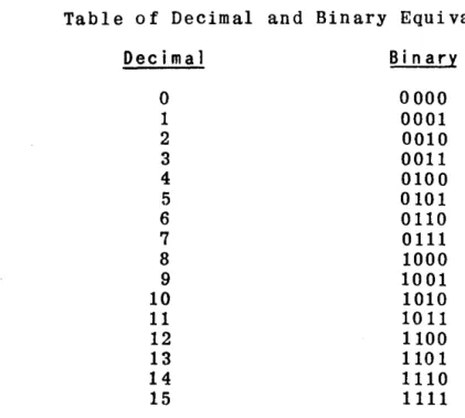
It is the purpose of this chapter to present the rela-tionships between the pulse patterns which UNIVAC accepts and the typewriter characters in which information is repre-sented. To represent the variety of characters needed, UNI-VAC uses the binary system of notation which is a primary characteristic fundamental to most digital computers. For introductory purposes it is sufficient to state that the absence of an electrical pulse is represented by zero and the presence of a pulse is represented by one.
The relationship between typewriter characters and pulse combinations is shown in the table on the last page of this chapter. Reference to this table will show, for example, that
o
is represented 1 00 0011 5 is represented 0 00 1000 M is represented 1 10 0111SEC. 2.
DECIMAL AND BINARY SYSTEMS OF NOTATION
For a better understanding of the defined pulse com-binations for numeric quantities employed by the UNIVAC system, i t is advisable to discuss, more fully, the binary system of notation and its relation to the decimal system of notation. In the discussion to follow, numeric charac-ters will be represented with only four pulse positions; the check pulse and "zone indicators" will be omitted. It must be remembered, however, that in the UNIVAC system all char-acters require seven pulse positions for representation.
In the Decimal Notation, the quanti ty three hundred fifty-nine is written in the decimal system, 359; i. e.,
( 3 xl 0 2 ) + (5 xl 0 1) + (9 xl 0 0) = 30 0 +50 + 9 359 ( 1)
where 102 100, 101 = 10, 10° 1
The left hand side of the equality (1) shows the basic com-posi tion 0 f the decimal, or "base ten" system. Each digi t
of (1) counting from right to left, is multiplied by suc-cessively higher powers of ten.
The binary system of notation uses two symbols (or digits) "0" and "1" as compared with the ten digits (0 through 9) used in the decimal system. For example, the decimal quantity nine, expressed in the binary system, appears as 1001. This is equivalent to stating that
where
23 = 8, 22 = 4, 2 1 = 2, 2° = 1.
The left-hand side of the equality shows the basic composition of the binary or "base two" system. Each digit of (2), counting from right to left, is multiplied by
suc-c e s s i vel y high e r po we r s 0 f two. Hen c e , the dec i m a I qua n t i
Table of Decimal and Binary Equivalents
Decimal Bin a ry
0 0000
1 0001
2 0010
3 0011
4 0100
5 0101
6 0110
7 0111
8 1000
9 1001
10 1010
11 1011
12 1100
13 1101
14 1110
15 1111
SEC. 3.
THE BINARY EXCESS-THREE SYSTEM
UNIVAC uses a modified binary code, called the excess-three system. Each decimal digit is represented, in binary, by its 0 rig ina 1 va 1 u e p 1 u s t h r e e. Rea son s , jus t i f yin g the
use of the "excess-three" system rather than the pure binary system, are given below in Section 11. In later discussions the symbolsU
O"and6
'l"used in the excess-three system will be referred to as binary zero and binary 1.
Table of Decimal and Excess-Three Equivalents
Decimal
o
1 2 3 4 5 6 7 DecimalExcess-Th ree 3 4 5 6 7 8 9 10
Bin a ry
Thus, 724
=
1010 0101 0111 where 7 10102
=
0101 4=
0111It should be clear that the UNIVAC system considers each digit of a quantity in binary excess-three notation which is somewhat different from the usual binary notation. For ex-ample the number 25 in the usual binary notations equals
But in digital binary (excess-three) notation
2 5
25
=
0101 1000SEC.~.
PRACTICE EXERCISES ON EXCESS-THREE REPRESENTATION
Represent the following quantities in binary excess-three notation. (Ignore zone indicators and check pulse). 1. 232. 407 3. 5891
What would be the 6-pulse code representation of the following quantities. (Ignore the check pulse).
SEC. 5. EXCESS- TH RE E COMPL EMEN T8
If two positive quantities when added together, produce a power of ten, one is said to be the ten's complement of the other. For example, the ten's complement of 724 is 276, sin c e 7 24
+
276 :II 1 0 00; the ten' s com pIe men t 0 f '5 1 i s 49 ,for 5 1 + 49
=
1 0 O. Sub t r act ion i s per form e d by add i n g the complement of the subtrahend to the minuend. Carry result-ing from the sum of the most significant digits is ignored. For exampl e,using complements,
892 - 724
=
168, 892 + 276=
168.In the excess-three system, compl ements on nine are ob-tained by substi tuting zeros for ones and ones
fO"r
zeros. Hence, complements on ten. would be obtained by increasing by one the least signifiC'i'Dt decimal digit of the nine's com-plemen tthus
4
=
01115
=
1000=
nine's complement of four 6=
1001 =- ten's compl emen t 0 f fou ralso
724
=
1010 0101 0111Decimal
o
1 2 3 4 5 6 7 8 9 Excess-Three 0011 0100 0101 0110 0111 1000 1001 1010 1011 1100 Excess-Three Nine's Complement1100 1011 1010 1001 1000 0111 0110 0101 0100 0011
It will be understood that when complements are refer-red to in succeeding exercises and discussions, tens' com-plements are implied.
SEC. 6. PRACTICE EXERCISES
Represent the complements of the following in excess-three notation (ignore zone indicators and check pulse) 1. 42
2. 436 3. 510 4. 7777
SEC. 7. EXCESS-THREE ADDI liONS
When two decimal digits are added which do not produce a ten's carry, the corresponding binary addi tion of their excess-three representations will exceed the correct sum by an three; i. e., the sum is too great by an excess-three correction:
Decimal 1
l.
4 Excess-Three 0100 0110 1010 = 7Page 20
Decimal 4 .Q.. 9 Excess-lh ree 0111 1000
Hence, if no carry occurs when two digits are added, an excess-three must be subtracted (complement of excess-three,
1101, added) from that digit to produce the correct sum. In
performing excess-three corrections, no carry is executed from decimal digit to decimal digit.
When two decimal digits are added to produce a ten's carry, the corresponding binary addi tion of their excess-three rep resentations will produce a carry from the fourth binary digi t posi tion. Thus, the excess-three correction is missing from the sum digi t; i. e., the sum is deficient by an excess-three correction:
Decimal
8
7 Sum 5 Carry
1
Excess-Three
1
1011 1010
0101 2
1
Decimal
9
9 8
Exces s-Th ree
1
1100 1100
1000 5
Hence, if a carry occurs when two digits are added, an excess-three must be added to that digit to produce the correct sum.
Example 1. Add 592 and 257.
592 1000 1100 0101
257 0101 1000 1010
1101 0100 1111
1 carry
1110 0100 1111
0011 correction if carry, + XS3
1101 110 1 cor rec tion if no carry, -XS3
SEC. 8. PRACTICE EXERCISES
Per fo rm the followin g addi tion s by means of the binary exces s- th re e method.
1. Add 3 and 4. 2. Add 9 and 5. 3. Add 25 and 40. 4. Add 18 and 46. 5. Add 478 and 903.
SEC. 9 • EX C E S S - T H R E E SU B T R ACT ION
Excess-three differences are obtained by adding the complement of the quantity, smallerin absolute magnitude, to the larger, and appending the sign of the larger.
Example 1: 72 - 34 2 38, using complements 72 + 66
=
38.In the excess-three system, 72 1010 0101 34
=
0110 0111 complement of 34 1001 1001.Hence, 72 1010 0101
complement of 34
=
1001 1001 0011 11101 carry
0011 correction if carry, + XS3 1101 correction if no carry, -XS3 38 0110 1011
SEC. 10. PRAl!TI CE EXERCI SES
Perform the following subtractions by means of the excess-three method. Add the complement of the smaller quantity to the larger quantity and append the sign of the larger.
1. 8 - 2
2. 82 - 55
3. 100 - 17
4. 325 - 109
5. 109 - 325
SEC. II. ADVANTAGES OF BINARY EXCESS-THREE SYSTEM
Two of the advantages in using the binary excess-three system are:
(a) It is electronically easy to represent comple-ments on ten in this system.
(b) A "carry" in the decimal system will produce a "carry" in the binary excess-three system, (e. g.) the addi-tion of 6 and 5 in the three systems are:
Decimal
carry 1
6
5
T
no carry
Bin a ry 0110 0101 1011
carry 1
Bin a ry
Excess-Th ree
1001 1000 0001
SEC. 12. SEVEN-PULSE CODE
For example, A = 01 0100 requires a check pulse in order t hat an 0 d d n u m be r 0 f p u I s e s be pre sen t, A = 1
a
1a
100; soalso 6 = 00 1001 becomes 6 = 1 00 1001. On the other hand, no check pulse is required by C = 01 0110 which becomes C =
o
01 0110. Frequent checks are made throughout the computer circuits to insure that each character is represented by an odd number of pulses.SEC. 13. IN TERNA L M Et>10 RY
The internal memory of the UNIVAC consists of acoustic delay lines. It contains 100 channels, each storing ten words. The "memory locations" of the 1000 words are
number-ed from 000 to 999. Every five seconds the entire content of the memory is automatically checked to insure the con-tinued correctness of the stored information.
Transfer of data into a memory location automatically erases any information previously stored in that location. However, reading from a memory location does not destroy its contents. The symbol, ( ), is used to mean "the contents of"; i. e., (m) = the contents of memory location m in the
computer, m being any number from 000 to 999.
SEC. 14. A COMPUTER "WORD"
Each memory location holds one "word" of information consistin g 0 f twel ve characters. A "word" of information
can be coded to take one 0 f two forms:
(a) It may consist of twelve characters, representing a numeric quantity or other data to be processed. When it is a numeric quantity, the twelve characters in the word are the algebraic sign, followed by eleven decimal digits. A "zero" in the sign position represents a plus sign. The computer in performing multiplication and division, con-siders the decimal point to lie immediately to the right of the sign position. Thus, all quantities X, are treated as falling in the range -1 < X < +1. It will be seen later how quantities outside this range are handled.
( b ) 0 r i t m ay t a k e the form 0 f two " ins t r u c t ion s" to the computer (e.g.)
BOO 120 C00185
Each instruction consists of six computer digits. The first two characters in each instruction designate the oper-ation to be performed (and will be defined in succeeding chapters) and the fourth, fifth and sixth digits in each in-struction designate a memory location. The third digi t (underlined and usually not written) is not decoded.
The computer performs the two instructions serially; the right instruction is executed after the left instruction has been accomplished.
SEC. 15. DI GI TAL POSI TIONS
In later discussions, reference will be made to dig-ital positions and, hence, some comment on this terminology is in order. Consider the twelve digital positions of a computer word,
1 2 3 4 5 6 7 8 9 10 11 12
The location labeled_1 is the first digit position and con-tains the sign of a numeric quantity. The location labeled
~ is referred to as the most significant digit (MSD) posi-tion and locaposi-tion 12. the least significant digit (LSD) position. When disctlssing non-numeric words, it is usually better to refer to the digital positions 1 to 12.
SEC. 16. PRACTICE EXERCISES
Using the seven-pulse code, in exercises 1 to 4, rep-resent the quantities:
1. A 425
2. R 310 U 100
3. I.
Represent the following quantities in the seven-pulse code, perform the operations indicated and represent the re-sult in seven pulses.
'"
P'
oq
C'D ~
~
ZONE
00
a
ff 0
f 1
-1
Il If
t
¥.
0000 0001 0010 0011 OtOO 0101 OHO 01 1 1 1000 100 1 1010 1011 1100 t 101 11 10 1 t 1 f
1 II
-
0 t 2 3 4 5 6 7 8 9~ t ; A B C 0 E F G H I
t
X
/ J K L M N 0 P Q R ItJJ
P Til
+
S T U V Wx
y Z ~
~--L -_ _ _ _ _ _ - - - -' - - - -L _ _ _ _ - -
-: IGNORE Jd : UNSHIFT
: SPACE 9J : ONE SHIFT (SINGLE SHIFT)
: CARRIAGE RETURN P : PRINTER STOP
: TAB if : PRINTER BREAKPOINT STOP
: SHIFT LOCK 181 = NOT AVAILABLE (USED INTERNALLY)
Section
1
2
3
4
5
6
7
Top i c
Preliminary Discussion Registers CC and CR
One-Word Registers A,X,L,F Multi-Word Registers V,Y,I,O One-Word Transfers Using
Register A Register X Register F
Multi-Word Transfers Using Register V
Register Y Register I Register 0 Practice Exercises
Page
28
29 29 30
31 31 32
33 35 36 36
SEC. I. PRELIMINARY DISCUSSION
In Chapter 2 it was stated that the internal memory of UNIVAC consists of memory locations capable of storing 1000 words. UNIVAC also employs certain addi tional "storage facilities" called registers, the functions of which are quite different from those of memory locations.
When instructions and other data are transferred to the computer from magnetic tape, they are placed into memory locations, and retained there until called upon to take part in the procedures. As these data are required for computation and other operations, they are processed through the regis-ters. These registers are used, then, to
(a) Transfer data between memory locations. (b) Perform arithmetic and control operations.
It is the purpose of this chapter to discuss these reg-isters and define the part they play in the processing of instructions and other data. In Chapter 9, the role 0 f
registers in the total logical pattern will be presented. It should be noted, first, that a register is said to be "erased" when it contains binary zeros. A register is said to be "cleared" when decimal zeros (in the excess-three code) replace its previous contents.
Several registers are required for temporary storage of data being processed by the computer. Two of these are one-word registers used for sequencing operations (CC, CR); four are one-word registers used for arithmetic and logical oper-ations (rA, rX, rL, rF); four are multi-word registers used to transfer data (rV, rY, rI, rO).
Throughout this manual, the symbol "m" represents a memory location number.
SEC. 2. REGISTERS CC AND CR
These two registers are concerned with the sequencing of control operations.
The control counter (CC) stores the number of the mem-ory location containing the next pair of instructions to be execu ted.
The control register (CR) stores the current pair of instructions.
Further discussion of these two registers will be de-layed until Chapter 8.
SEC. 3. ONE-WORD REGISTERS
The four registers, rA, rX, rL, and rF, are duplicated within the computer. The contents of the duplicated regis-ters are continuously compared by checking circuits which immediately detect any discrepancy between the duplicated quantities.
Register A is used for: (a) one-word transfers
(b) storing the addend (minuend) in addition (sub-traction)
(c) retaining a partial or complete algebraic sum ( d) s tor in g the m 0 res i gn i f i can t h a I f 0 f a t wen ty - two
digit product or a rounded eleven digit product after multiplication
(e) storing the dividend at the start of division (f) storing the rounded quotient after division
(g) retaining a quantity to be shifted right or left, and performing the shift
(i) storing one component of a comparison Register X is used for:
(a) one-word transfers
(b) storing the augend (subtrahend) in addition (subtraction)
(c) storing the multiplier during multiplication (d) storing the less significant half of a
twenty-two digit product after multiplication
(e) storing the unrounded quotient after division Register L is used for:
(a) storing the multiplicand during multiplication (b) storing the divisor during division
(c) storing one component of a comparison Register F is used for:
(a) one-word transfers (b) storing the extractor
(c) storing three times the absolute magnitude of the multiplicand during multiplication.
SEC. ij. MULTI-WORD REGI STERS
Register V is used for two-word transfers Register Y is used for ten-word transfers
Register I is used to assemble "one block", 60 words, read from tape for transfer into the memory. Register 0 is used to store one block from the memory
SEC. 5. ONE-WORD TRANSFERS
Register A
Instructions
Bm Erase rA and rX; transfer (m) to rA and rX. Cm Transfer (rA) to m; clear rA to decimal zeros Hm Transfer (rA) to m; do not alter rA
Km Transfer (rA) to rL clear rA; ignore m.
A complete one-word transfer using rA involves two instructions; (a) transferring a quantity from the memory to rA, and (b) transferring the quantity from rA to the memo rYe
Example 1: (0"50) :: a. Transfer "a" to 051 and 052. Mem.
Loc.
020
021
Instruc tion
B 050
H 051
C 052
Register X
Remarks
a --> rA and rX
(rA) :: a --> 051; (rA) :: a --> 052;
(rA) =. a
o - -
> rAInstructions
Bm Erase rA and rX; transfer (m) to rA and rX. Lm Erase rL and rX; transfer (m) to rL and rX. Jm Transfer (rX) to m; do not erase rX.
A complete one-word transfer using rX involves two instructions; (a) transferring a quantity from the memory to rX, and (b) transferring the quantity from rX to the memory.
Example 1: (050)
=
a. Transfer "a" to 051 and 052. Mem.Loc.
020 021
Instruction Remarks
8 050
J 052
a --> rA and rX
C 051 (rA)· a --> 051; 0 --> rA (rX) • a --> 052; (rX)
=
a. Example 2: (050) = a. Transfer "a" to 051 without disturb-ing (rA)Mem. Loc.
020
Register F
Instruction Remarks
L 050 a - -> rL an d rX
J 051 (rX) = a --> 051; (rX) = a.
Instructions
Fm Erase rF; transfer (m) to rF.
Gm Transfer (rF) to m; do not erase rF.
Example 1: (050) = a. Transfer "a" to 051, without dis-turbing (rA) or(rL).
Mem. Loc. 020
Instruction
F 050
G 051
Remarks a --> rF
(rF) = a --> 051; (rF) = a. Interchange: Two quantities may be interchanged by means of one- wo rd tran sfers.
Example 1: (050) = a. ( 0 5 1 ) = b . I n t e r chan g e " a" an d I I b" .
Mem. Loc. 020
021
Instruction
B 050
L 051
C 051
J 050
Remarks a - - > rA b --> rL ( rA) a ( rX) = b
and rX and rX
--> 051; 0 --> rA --> 050; ( rX) = b.
SEC. 6. MULTI-WORD TRANSFERS
All multi-word transfers erase the registers or memory locations to which they are directed with the exception of rIo
Register V
Instructions
Vm Erase rV; transfer two consecut i ve words, start-ing with m, to rV; m is usually a multiple of two. For other cases see paragraphs to follow. Wm Transfer (rV) to two consecutive memory locations,
starting with m; do not erase rV; m is usually a multiple of two. For other cases see paragraphs
A
complete two-word transfer using rV involves the two instructions: (a) transferrin g two successi ve words from the memory to rV, and (b) transferring the two quantities from rV to the memory.Example 1: (050) = a, (051) = b. Transfer "a" and "b"to
096 and 097 respectively. Mem.
Loc. 020
Instruction Remarks V 050 a, b - -> rV
W 096 a - -> 096; b - - > 097; (rV) = a, b. If the m in both the Vm and Wm instructions is odd and the least significant digit is not equal to nine, the in-structions behave as in the following example.
Example 2: (051) = a, (052) = b. Transfer Ha" and "b" to 063 and 064 respectively.
Mem. Loc. 020
Instruction Remarks V 051 a, b --> rV
W 063 a--> 063; b --> 064; (rV) = a, b.
If the m in one instruction is odd (least significant digi t not equal to nine), and the m of the other instruction is even, the two wo rds are transfer red in reversed 0 rder.
Example 3: (051) = a, (052) = b. Transfer fib" followed by
.. a" toO 54 an d 0 55 res p e c t i vel y . Mem.
Loc. 020
Instructions Remarks V 051 a, b - - > rV
Example 4: (050) = a, (051) = b. Transfer lib" followed by "a" to 063 and 064 respecti vely.
Mem. Loc. 020
Instruction
V 050
W 063
Remark s a, b - - > rV
b --> 063; a --> 064; (rV)=a, b
If the m in a Vm or Wm instruction has a nine as its 1 east signi fican t di gi t, the in struc tion wi 11 tran sfer from, or to, the last and first words in the ten-word memory chan-nel.
E x am pIe 5: ( 0 50 ) = a, ( 0 59 ) = b . Transfer " a " followed by "b" to 100 an d 10 1.
Mem. Loc. 020
Instruction
V 059
W 100
Register Y
Remarks
b, a - - > rV
a --> 100; b --> 101; (rV) b, a.
Instructions
Ym Erase rY; transfer ten consecutive words start-in g wit h m, to r Y ; m s h a u 1 d bean in t e g r aIm u 1 t i -pIe of ten
A complete ten-word transfer using rY involves two in-structions; (a) transferring ten successive words from the memory to rY, and (b) transferring the ten quantities from rY to the memory.
Example 1: (050) = ao ' (051) = at, ... , (059)
"ao '" .,ag " to 100, ... ,109 respectively
ag • Trans fer
Mem. Loc. 020
Instruction Y 050
Z 100
Remarks
ao ' ••• , ag - - > rY
ao --> 100, ... ,ag --> 109; (rY) = a o " ' " ag •
When executing a Ym or Zm instruction, the least significant digit of m is ignored by the computer. The transfers operate on the integral multiples of ten. Thus, Y999 is equivalent to Y990, and Z7B4 to Z7BO.
Register I
Register I does not erase upon read in, but only upon transferral of its contents to the memory. The tape in-structions reading into rI will be discussed in Chapter B.
Instructions
30m Transfer sixty words stored in rI to sixty consecutive memory locations, starting with 40m m; m should be an integral multiple of ten;
erase rI.
Regi ster 0
Register 0 holds sixty words during a wri te instruction. Register 0 cannot be used independently of the tape
SEC.
7.PRACTICE EXERCISES
Problems on the transfer of data Given
(052)
x
1( 053)
x
2 (054) X3(055) x4
(056) = Xs
(057) X6
(058) x7 (059) Xs (060) = Xg
(061 )
x
10In each of the following problems write the instructions to perform the operations indicated; start wi th memory loc-ation 020. Choose any unused memory locations for working storage.
1. Transfer quantity x1 to 050 and 051 using
(a) r.A (b) rX (c) rF
3. T ran s fer x I to 0 5 3, X 2 to 0 54, X 3 to 0 5 3 an del ear r A.
4 . T ran s fer x I t o 048 an d 046, X 2 too 49 an d 045 us i n g
the V, W instructions.
5. Move the given 10 quantities up two memory locations i.e., XI --> 050, x
SECTION
1
2 3
4
5 6 7 8 9
10
11
12
TOPIC
Preliminary Discussion Addition
Practice Exercises Subtraction
Practice Exercises Multiplication Practice Exercises Division
Practice Exercises
Review Practice Exercises Special Consideration in
Arithmetic Computation Addition and Subtraction Multiplication and Division Practice Exercises
PAGE
39
40
42 43
44
45
47
48
49 50
SEC. I. PRELIMINARY DISCUSSION
The purpose of this chapter is to explain UNIVAC in-structions for addition, subtraction, multiplication, divi-sion and to consider certain special problems closely allied to these operations. Before del ving into these detail s, it is advisable to review some concepts, previously discussed.
(a) The internal memory of UNIVAC consists of 100 channels, each storing ten words. The "memory locations" of the 1000 words are numbered from 000 through 999.
(b) A "wo rd" may have the form 0 f two instruction s or may be information composed of twelve typewriter characters.
(c) The instructions in a "computer word" are executed serially, first the left instruction followed by the right instruction.
(d) The symbol (m) represents "the contents of memory location m."
(e) A transfer into a memory location erases any in-formation previously stored in that location but reading from a memory location does not destroy its contents.
(f) There are four one-word registers - rA, rX, rL, rF; the multi-word registers are rV, rY, rI, rOo
(g) A complete transfer involves two instructions --transferring a quantity from a memory location to a register, and then, transferring the quantity from the register to a memory location.
(a) The algebraic addi tion, subtraction or di vision of numeric quantities, considered as decimals by UNIVAC, may lead to resul ts greater than plus one or I ess than minus one. This situation, called "overflow" must be handled by special techniques which will be described in Chapter 7.
(b) In the study of instructions for arithmetic manip-ulation, the question may arise as to computer responses to
quantities that contain characters, other than numeric. A
discussion of this problem will be found at the end of this chapter.
Finally, it will be noted that the instructions, pre-viously defined, are restated in this chapter. ,A complete table of instructions may be found at the back of this man-ual and it is so placed for easy reference.
SEC. 2.
ADDITION
Instructions
Am Transfer (m) to rX; add (rX) to rA); deliver the sum to rA; do not erase rX.
Bm Erase rA and rX; transfer (m) to r,A and rx. Cm Transfer (rA) to m; clear rAe
Hm Transfer ( rA) to m; do not clear rAe Jm Transfer ( rX) to m; do not erase rX. Km Transfer ( rA) to rL; clear rA; ignore m.
Sm Transfer -(m) to rX; add (rX) to (rA); deliver
the difference to rA; do not erase rX.
Xm Add (rX) to (r A); del i ver the sum to rA; do no t
A complete addition involves three instructions; (a) tran sferring the addend to r A, (b) t ran sferring the augend to rX, adding (rX) to (rA), and del i vering the sum to rA, and (c) transferring the sum from rA to the memory.
Example 1: (049)
=
x, (050) = y. Deliver the sum x+y = z to 051.Mem.
Loc. Instruction 020 B 049
021 C 051
.A 050
Remarks
X --> rA and rX
y --> rX; x+y = z --> rA (rA) = z --> 051; 0 --> rA.
Exampl e 2: (049) = x, (050) = y. Del i ver the sum p = x+y+y to 051.
Mem.
Loc. Instruction Remarks
020 B 049 x --> rA and rX
A 050 y --> rX; x+y = Z --> rA; (rX)=y 021 X 000 z+y = P --> rA
C 051 ( r.A) = p --> 051; 0 -- > rA.
Example 3: (049) = x, (050) = y, (051) = z. Deliver the sum x+y = p to 052, and the sum x+y+z = q to 053. Mem.
Loc. Instruction Remarks
020 B 049 x --> rA and rX
A 050 y --> rX; x+y = p --> rA; (rX)=y 021 H 052 ( rA) = p --> 052; ( r.A) = p
SEC. 3.
PRACTICE EXERCISES ON ADDITION
In the problems to follow:
(049) = x, (050) = y, (051) = Z
use any memory location for working storage. Write the instructions to:
1. Deliver 3x to 060.
2. Deliver the sum x+2y to 060. 3. Deliver the sum 2x+3y to 060. 4. Deliver the sum 2x+y+3z to 060. 5. Deliver
2x+y to 060 3x+y to 061 2x+2y to 062 6. Deliver
x+y to 060 y+z to 061
z+:r to 062
2(x+y+z) to 062
SEC.~.
SUBTRACTION
A complete subtraction invol ves three instructions; (a) transferring the minuend to rA, (b) transferring minus the subtrahend to rX, adding (rX) to (rA), and delivering the difference to rA, and (c) transferring the difference from rA to the memory.
E x amp 1 e 1: ( 049) x, ( 050 ) x-y = z to 051.
y. Deliver the difference
Mem.
Loc. Instruction
020 B 049
021 C 051
S 050
Remarks
x - -> r A an d r X
-y --> rX; x-y = z --> rA; (rX) =-y
(rA) = z --> 051; 0 --> rA.
Example 2: (049) = x, (050) = y, (051) = z. Deliver the dif-fer en c e p = x - y to 05 2 an d the sum q = x - y + z to rL.
Mem.
Loc. Instruction
020 B 049
S 050
021 H 052
A 051
022 K 000
Remarks
X --> rA and rX
-y --> rX; x-y = p --> rA; (rX)=-y (rA) = p -- > 052; (rA) = p
z --> rX; p+z = q --> rA; (rX)=z ( r A) = q - - > rL; 0 - - > r A .
E x am pIe 3: ( 0 49 ) b . I t i s des ire d too b t a in - b w hen (a) rA is not cleared or (b) b = O. This should be used with caution because there is a possibility of overflow depending on (rA).
Mem.
Loc. Instruction
020 S 049
J 050
Remarks
SEC. 5.
PRACTICE EXERCISES ON SUBTRACTION
In the problems to follow:
(049) = x, (050) = y, (051) = Z
provide the instructions to: 1. Deliver
2. Deliver
3. Deli ver
(a) x-y to 060
(b) y-x to 061
( c) y - z to 0 6 2
(a) -y to 060
(b) 2x-y to 061
(c) 2x-y+z to 062
(a) x-2y to 060
(b) x-2z to 061
SEC. 6.
MULTIPLICATION
Instructions
Jm Transfer (rX) to m; do not erase rX. Km Transfer (rA) to rL; clear rA; ignore m. Lm Transfer (m) to rL and rX.
Mm Transfer (m) to rX; mul tiply (rL) by (rX) = (m); deli ver the rounded eleven digi t product to rA; (rL) unal teredo
Nm Transfer - (m) to rX; mul tiply (rL) by (rX) - (m) ; deliver the rounded eleven digi t product to rA; (rL) unal teredo
Pm Transfer (m) to rX; mul tiply (rL) by (rX) = (m);
deliver the more significant half of the twen-ty-two digit unrounded product to rA, the less signi ficant hal f to rX; (rL) unal teredo
The instructions M, N, and P leave three times the ab-solute magnitude of the multiplicand in rF.
The instructions M and N leave the less significant half of the twenty-two digit product ±50000 000000 in rX.
The quantity having the fewer non-zero digits should be selected as the multiplier since multiplication by zeros consumes less time than multiplication by a non-zero digit.
A complete multiplication requires three instructions; ( a) t ran sf err i n g the m u 1 tip 1 i c an d to rL, (b) t ran s fer r i n g the multiplier to rX, initiating the multiplication opera-tion, and de:!.ivering the product to rA and rX, and (c) transferring the product from rA (and rX) to the memory.
Example 1: (049) x, (050) = y. Deliver the eleven digit rounded product xy = z to 051.
Mem.
Loc. Instruction
020 L 049
M 050
021 C 051
Remarks
x - -> rL, an d rX
y --> rX; xy = z --> rA; (rL)=x (rA) = z --> 051; 0 --> rA.
Example 2: (rA) x, (050) = y. Deliver the eleven digit z to 051, leave z in rA. rounded product -xy
Mem.
Loc. Instruction Remark s
020 K 000 ( rA) = x --> rL
N 050 -y --> rX; - xy = z - - > rA; (rL)=x
021 H 051 ( rA) = z --> 051; ( rA) = z.
Example 3: (049) = L (050) = M. Deli ver the twenty-two di-git unrounded product P = LM to 051 and 052. Mem.
Loc. Instruction Remark s
020 L 050 M --> rL and rX
P 049 L --> rX; LM = P --> rA and rX; (rL) = M
021 J 052 ( rX) less significant half of
p = P --> 052 C 051 ( rA) more significaAt half of
p = P
Example 4: (049) = L, (050) = M, (051) = N. Deliver LM = P 1 toO 52 an d N 1,1 = P ~ too 5 3, e I eve n dig i t un
-rounded products are desired. Mem.
Loc. Instruction Remarks
020 L 050 M --> rL and rX
P 049 L --> rX; LM = P - - > rA; (rL)=M 021 C 052 ( rA) = P1 --> 052; 0 --> rA
p 051 N --> rX; NM = P --> rA; (rL)=M
--> 053; 0 --> rAe
022 C 053 ( rA) = P2
SEC. 7.
PRACTICE EXERCISES ON MULTIPLICATION
(040) = x
(041) y
(042) Z
Write the instructions to deliver eleven digit rounded products.
1. (a) xy to 050
(b) xz to 051
(c) yz to 052
(d) xyz to 053
Write the instructions to deliver eleven digit rounded products.
2 . ( a) x 2 = 0 50
(b) -X3 051
(c) X4 052
Write the instructions to deliver eleven digit rounded products.
3. (a) (X-y)2 to 050 and 051
(b) (x-y) (x-z) to 052 and 053 (c) X(y-Z)2 to 054 and 055.
SEC. 8.
DIVISION
Instructions
Jm Transfer ( rX) to m; do not Km Transfer ( rA) to rL; clear Lm Transfer (m) to rL and rX. Dm Transfer (m) to rA; divide
deliver the eleven digit
erase rX. rA; ignore m.
( rA) = (m) by (rL) ;
rounded quotien t to rA, and the eleven digit unrounded quotient to rX; ( rL) unal teredo
Since all quantities, x, in the UNIVAC, must fall in the range
I
xl < 1, the absolute value of the di vidend must be less than the absolute value of the divisor so that a proper d i vis ion s hall ta k e pI ac e . I fI
D dI
?I
DrI,
0 r i f an a t t e m p tis made to di vide by zero, an overflow will resul t (see Chap-ter 7).
Example 1: (049) = A, (0'50)
=
B. Deliver the eleven digi t rounded quotient C=
AlB to 051.Mem.
Loc. Instruction Remarks
020 L 050 021 C 051
D 049
B - - > rL an d rX
A --> rA; AlB = C --> rA; (rL)=B (rA) = C --> 051; 0 --> rAe
Example 2: (049)
=
A, (050) = B. Deliver the eleven digit unrounded quotient C AlB to 051.Mem.
Loc. Instruction Remarks
020 L 050 B - -> rL and rX
D 049 A --> rA; AlB
=
C - - > rX; (rL)=
B021 J 051 ( rX) = C --> 051.
SEC.
9. P~ACTICEEXERCISES ON DIVISION
Assume that overflow will not occur in these exercises. (050)
=
x(051) y
(052) z
Write the routines to send 11 digit rounded quotients .
1. ( a) ..! y to 060 and 061
(b) .! y to 062
2. (a) llto 060 z
( b) ~ z to 061
SEC. I O. REV I EW P R ACT ICE EX E R CIS E SON THE A R I T H MET I COP ERA T I 0 H S
(050) x
(051) - y (052) Z
(053) 1
Assume that adjustments have been made so that overflow will not occur in these exercises. Wri te the instructions
to send:
1. x 2+3y2_2z to 060 2. (X+y)2 to 061 3. 1 + 1 + 1 to 062
x y Z
4. x 2 2z y to 063
y y 4
SEC. II. SPECIAL CONSIDERATION IN ARITHMETIC COMPUTATION ADDITION AND SUBTRACTION
When two numeric quantities are to be added (or sub-tracted), UNIVAC compares the signs of the quantities in-volved, performs the addition (or subtraction) on the terms digit by digit and delivers the correct result (including the sign) to rA. This, of course, presumes that overflow has not occurred and that decimal points have been properly aligned. Overflow will be considered, in some detail, in Chapter 7, and decimal point alignment is handled in Chapter 6. Al so, it should be men tioned that the internal logic with which a computor performs these ari thmetic operations is discussed in Chapter 9.
which are not wholly numeric or/and which contain charac-ters, other than 0 (plus) or - (minus), in the sign posi-tion.
Consider, first, the digital positions excluding the sign. In the addition and subtraction processes, the cir-cuits by-pass alphabetic and typewriter characters and, hence, these quantities take precedence over numeric digits. A minus, not in the sign position, is treated as a digit. This means, for example, when a letter is added to (or sub-tracted from) a numeric digit the letter prevails and is shown in the result; the numeric character is ignored.
If any two characters, other than numeric, appear in a given digit the UNIVAC stops and shows an error neon. To illustrate, in a digit (other than sign) position:
4+3 7 4+B B 4+(-)
=
3Following are two tables showing UNIVAC responses to add and subtract orders on non-numeric quantities.
ADDITION
AUGEND
ADDEND
o
~ 0 + = 0-
c
-
00 ~ 0 or+O 0 0-1 C
+ = 0 0 +
-
C-
o -
1-
~ CC C C C
E
SUBTRACTION
MINUEND
SUBTRAHEND
D ~ 0 +
=
0-D "I- 0
0
-0 -0-1
or+O
+
=
0 D + -1-
D t 1* 1 +C C C C
D= DIGIT
C = CHARACTER
6.= SPACE
C
C
C
C
E
0= DIGIT
C = CHARAOTER
6,= SPACE
E = ERROR STOP
Exampl e 1: Subtract 0---- from 09999.
9999 1100 1100 1100 1100 complement ---- 1101 1101 1101 1110 1010 1010 1010 1010
0011 0011 0011 0011 correction if "10"10"10"10" 1101 1101 1101 1101 carry, + XS3 '
0000 0011 0011 0011 0011 0001 0001 0001 0000
0011 0011 0011 0011 correction if 1110 0100 0100 0100 0011 carry, + XS3 Example 2: Subtract 0---- from 05394.
5394 1000 0110 1100 0111
complement 1101 1101 1101 1110
0110 0100 1010 0101
0011 0011 0011 0011 correction if 64"10"5 1001 0111 1101 1000 carry, + XS3
00
o
0 0011 0011 0011 00111100 1011 0000 1011
1101 1101 0011 1101 correction 6'50'5 = 1001 1000 0011 1000
In the sign position, the circuits by-pass all symbols except a plus (0) or minus sign, and, hence, the symbols take precedence over the signs. If any combination of sym-bols other than the two signs appears in the sign position, an error stop results. In the case of subtraction, a digit or character subtracted from a sign leads to a different di&it or character in the result. This is occasioned b7 the precedure, iaherent in UNIVAC design which adds 1 00 0001, . witbout binary carry, to the character in the sian position
of the subtrahend. To illustrate:
When subtracting a plus quantity
o
= 1 00 0011the computer adds 1 00 0001
the result is minus 0 00 0010
When subtracting a negative quan ti ty - 0 00 0010
the computer adds 1 00 0001
the result is plus
o ".
0 01 0101When subtracting B B 0 01 0101
When subtracting A the computer adds The result is B
A
=
1 01 0100 1 00 0001 B=
0 01 0101 Therefore, in the sign positiono
+ 0=
0(-) + (-)
= (-)
B + 0 = B
B + R - Error stop
o
B=
ABelow is a table showing, in part, the resul t in the sign position of subtract and add orders. A more complete
rep-resentation of the 8m instruction in the sign column is shown on page 238 in the Appendix.
ADDEND AUGEND OR MINUEND
OR
SUBTRAHEND D ~ 0
+
= 0-
Co
~0
E *0*D
E+ = 0 D + + - C
-
0 + - C 0= DIGITC= CHARACTER
C E *C *C E E. = ERROR STOP
A negative zero cannot be obtained as a result of an addition or subtraction except in the cases -0 + (-0)
=
-0 and -0 - (0) = -0. In all other cases, if two quantitieswith opposite signs are equal, the positive, sign is appended to the difference.
Multiplication and Division
A digit or a character in the sign position of a factor in mul tip I ica tion 0 r di vis ion is tr'eated as a pI us si gn.
Furthermore, alphabetic characters in the other dig-ital positions of the multiplicand, multiplier, dividend or divisor do not stop the UNIVAC. Since, in the multiplica-tion and division processes, the zone indicators are ign&r-ed, all characters are treated as numeric digits. The be-havior of such symbols as J and ~ may be determined by carrying out these operations using the excess-three code. The following pulse combinations may appear in such a pro-cedure:
Excess-Three Decimal Equivalent
0000 -3 or 13,