~, _ -1
~ 'I
"
Connection Machine® Model CM-2 Technical Summary
Thinking Machines Corporation
Technical Report Series
Thinking Machines Technical Report HA87-4
Connection Machine
®Model CM-2
Technical Summary
Connection Machine is a registered trademark of Thi~king :Machines Corporation. Dat'aVawt, C*, *Lisp, C~
... Lisp,
and'Paris 8:re"tr~em:arkS %or'>;·~·>' .... :.~., ' 'Thinking MaChines' CorporatfHn. ,') "
~ymboJics3600 is a (radelli&r~ of Syriibopcs, Inc.
tNixis ~trademark
ofAT&:T :aefiLl!.h6i~toiies;VAX, VAXBI, and UI.TIUX ar~registeied traderiiark~
'or
Di~rta.fEqlilpment 90rporation., , ~ ,;:. . , r." ~'.::~ ;!:-f." :
';i'he infonnation in this document is subject to change witho~t notjc~ and sJtouJd not be c()nstlu~d 'as
it.
commitmen~ by ThinkiJigMaelihi~) Co;potation:' 'lpliilti'rigMachines !96rpo~ation reserveS thenght to make dlank~s ('0 'anY ~r()4u~~s d~~il~,l:)~4 herein to'iJUprOve functioning or design. Althouglitlieinformatl<>it
in
t1i~~~uriIen~}laS been reviewed and . is 'believecl to be reliable, Thhikihg' Machin'es'q6~'P'6r~ti()n
do~s not assume responsibility or liability for anyeriots
tpaf'mliyappear
iIanii;document:' Thinking Machines Corporation does
not 'a:Ssuttle
a'ri.Y)liti~H·~ titisth'gContents
1 Introduction
1.1 The Connection Machine System 1.2 Data Parallel Hardware
1.3 Data Parallel Software . . . .
2 System Organization
3 The Paris Language
3.1 Overview . . . • . . . 3.2 Virtual Machine Model. . . . 3.3 Organization of the Instruction Set. 3.4 Instruction Set Summary . . . .
4 Processor Architecture
4.1 Data Processors . . . . 4.2 The Router . . . • . . . . 4.3 The Floating Point Accelerator
5 The Role of the Front End
5.1 Applications Development . . . . 5.2 Running Connection Machine Applications 5.3 Maintenance and Operations Utilities . . •
5.4 The Digital Equipment Corporation VAX As a Front End • 5.5 The Symbolics Lisp Machine As a Front End . . . .
6 Connection Machine I/O Structure
7 The Connection Machine DataVault 7.1 The File Server . . . .
7.2 Off·line Loading and Backup . . . . . 7.3 Writing and Reading Data . • . . . . 7.4 Drive Failure and Data Base Healing .
8 High-Resolution Graphics Display
9 Languages
10 The C* Language
10.1 Data Parallel Machine Model
10.2 Parallel Expressions . . . • . . . 10.3 Parallel Statements. . . . . . .
10.4 Compiler Implementation . . . • • .
11 Fortran
11.1 The Environment . . . • . . . . 11.2 The Array Extensions of Fortran . . . • . . 11.3 Fortran Statements for Controlling Context 11.4 futerprocessor Communication in Fortran 11.5 Fortran and the Data Parallel Approach.
12 The "'Lisp Language
12.1 Pvars: The Basic *Lisp Data Object . . . . • • • • . . 12.2 Processor Addressing. . . . • . . • • • • • • . • • . • . 12.3 Reading and Writing Data from and to Pvars ••••• 12.4 Basic Parallel Operations . . . . . . • • • . . . . • . 12.5 Selection of Active Sets of Processors . -. • . . •
12.6 Communication between Processors •. 12.7 Global Reduction Operations . .
12.8 Summary . . . . .
13 The eM-Lisp Language
13.1 Xappings, Xets, and Xectors . . . . 13.2 Parallel Computation: a Syntax . • . . . 13.3 futerprocessor Communication:
f3
Syntax 13.4 Library Functions. . . • . •14 An Example Program
14.1 The Example Program in C*
14.2 The Example Program in Fortran .• 14.3 The Example Program in *Lisp . ~
14.4 The Example Program in CM-Lisp
15 Performance Specifications
15.1 General Specifications . . . . . . . 15.2 fuputjOutput Channels . . . . 15.3 Typical Application Performance (Fixed Point) 15.4 futerprocessor Communication. . . . 15.5 Variable Precision Fixed Point .
15.6 Double Precision Floating Point. 15.7 Single Precision Floating Point .
15.8 Parallel Processing Unit Physical Dimensions
15.9 Parallel Processing Unit Environmental Requirements .
42
. . . . . . 42
1
1
Introduction
The Connection Machine Model CM-2 is a data parallel computing system. Data par-allel computing associates one processor with each data element. This computing style exploits the natural computational parallelism inherent in many data-intensive prob-lems. It can significantly decrease the execution time of a problem, as well as simplify its programming. In the best cases, execution time can be reduced in proportion to the number of data elements in the computation; programming effort can be reduced in proportion to the complexity of expressing a naturally parallel problem statement in a serial manner. In order to fully exploit these potential benefits, a computing sys-tem consisting of both hardware and software that support this model of computing is required.
The Connection Machine Model CM-2 is an integrated system of hardware and software. The hardware elements of the system include front-end computers that pro-vide the development and execution envIronments for the system software, a parallel processing unit of 64K processors that execute the data parallel operations, and a high-performance data parallel I/O system. The system software is based upon the operating system or environment of the front-end computer. The visible software ex-tensions are minimal. Users can program using familiar languages and programming constructs, with all the development tools provided by the front end. Programs have normal sequential control flow; new synchronization structures are not needed. Thus, users can easily develop programs that exploit the power of the Connection Machine hardware.
1.1 The Connection Machine System
At the heart of any large computational problem is the data set: some combination of interconnected data objects, such as numbers, characters, records, structures, and arrays. In any application this data must be selected, combined, and operated upon. Data level parallelism takes advantage of the parallelism inherent in large data sets.
At the heart of the Connection Machine Model CM-2 system is the parallel pro-cessing unit, which consists of thousands of processors, each with thousands of bits of memory. These processors can not only process the data stored in their memory, but also can be logically interconnected so that information can be exchanged among the processors. All these operations happen in parallel on all processors. Thus, the Connection Machine hardware directly supports the data parallel problem model
One way to view the relationship of the CM-2 parallel processing unit to the other parts of the system is to consider it as an intelligent extension to the memory of the front-end computer. The data parallel data objects are stored by assigning each one to the memory of a processor. Then the operations on these objects can be specified to operate simultaneously on any or all data objects in this memory.
2 Connection Machine Model CM-2 Technical Summary
Machine memory during execution of the program and are operated upon in parallel at the command of the front end. This model differs from the serial model of processing data objects from a computer's memory one at a time, by reading each one in turn, operating on it, and then storing the result back in memory before processing the next object.
The flow of control is handled entirely by the front end, including storage and execution of the program and all interaction with the user and/or programmer. The data set, for the most part, is stored in the Connection Machine memory. In this way, the entire data set can be operated upon in parallel through commands sent to the Connection Machine processors by the front end. The front end can. also operate upon data stored in individual processors in the Connection Machine, treating them logically as memory locations in its virtual memory.
There are several direct benefits to maintaining program control only on the front end. First, programmers can work in an environment that is familiar. The front end interacts with the Connection Machine parallel processing unit using an integrated command set, and so the programming languages, debugging environment, and oper-ating system of the front end remain relatively unchanged. Second, a large part of the program code for any application pertains to the interfaces between the program, the user, and the operating system. Since the control of the program remains on the front end, code developed for these purposes is useful with or without the Connection Ma-chine parallel processing unit, and only the code that pertains specifically to the data residing on the Connecti9n Machine processors needs to use the data parallel language extensions. Finally, parts of the program that are especially suited for the front end, such as file manipulation, user interface, and low-bandwidth I/O, can be done on the front end, while the parts of the program that run efficiently in parallel, namely the "inner loops" that operate on the data set, can be done on the Connection Machine.
In this way, the individual strengths of both the serial front end and the Connection Machine processors can be exploited.
In general, the Connection Machine system appears to be a very powerful extension of the front-end system. The data parallel hardware looks like intelligent memory; the data parallel software extends the front end's capabilities to allow the direct execution of parallel operations.
1.2 Data Parallel Hardware
The Connection Machine system implements data parallel programming constructs directly in hardware. The system includes 65,536 physical processors, each with its own memory. Parallel data structures are spread across the data processors, with a single element stored in each processor's memory. When parallel data structures have more than 65,536 data elements (the normal case), the hardware operates in virtual processor mode, presenting the user with a larger number of processors, each with a correspondingly smaller memory.
Chapter 1 Introduction 3
a high-speed routing network. Processors that hold interrelated data elements store pointers to one another. When data is needed, it is passed over the routing network to the appropriate processors.
Scalar data is held in a front-end processor. The front end also controls execution of the overall data parallel program. Program steps that involve parallel data are passed over an interface to the Connection Machine parallel processing unit, where they are broadcast for execution by all the processors at once.
The Connection Machine front end provides the programming environment for the system. Programs can be stored on front-end disks. Network communications links are most effectively implemented on the front end as well.
High-speed transfers between peripheral devices and Connection Machine memory take place through the Connection Machine I/O system. All processors, in parallel, pass data to and from I/O buffers. The data is then moved between the buffers and the peripheral devices. Connection Machine high-speed peripherals include the Data Vault mass storage system and the Connection Machine graphics display system.
1.3 Data Parallel Software
The Connection Machine system software is designed to utilize existing programming languages and environments as much as possible. The languages are based on well-known standards; the extensions to support data parallel constructs are minimal so that a new programming style is not required. The CM-2 front-end operating system (either UNIX or Lisp) remains largely unchanged.
Fortran on the Connection Machine system uses the array extensions in the draft Fortran 8x standard (proposed by ANSI technical committee x3J3) to express data parallel operations. The remainder of the language is the standard Fortran 77. No extension is specific to the Connection Machine; the Fortran 8x array extensions map naturally onto the underlying data parallel hardware.
The *Lisp and CM-Lisp languages are data parallel dialects of Common Lisp (a version of Lisp currently being standardized by ANSI technical committee x3J 13). * Lisp gives programmers fine control over the CM-2 hardware while maintaining the flexibility of Lisp. CM-Lisp is a higher-level language that adds small syntactic changes to the language interface and creates a very powerful data parallel programming language
The C* language is a data parallel extension of the C programming language (as described in the draft C standard proposed by ANSI technical committee x3J 11). C* programs can be read and written like serial C programs; the extensions are unobtrusive and easy to learn.
4
2
System Organization
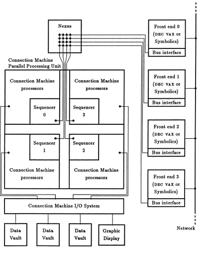
The Connection Machine Model CM-2 is a complete computing system that provid~s
both development and eXecution facilities for dl:).ta parallel progr~. It~ hardwaJ'e consists of a parallel processing unit containing thousa;nds of datI:). processor~, from one to four front-end computers, and an I/O system that supports J:IlASS storage cmd graphic display devices (see Figure 1). The user interacts with. the f.ront~end computer; all progr&m development and execution t8kes place withJn the front ent!. Because the front-end computer runs standard serial software, fb.e user sees .. familar sYlltem environment with additional languages and utilities and some very powerful hardware. The central element ~ the system is the CM-2 plU'allel processing unit, which contains:
• thousands of data processors
• an interprocessor communications network
• one or more sequencers
• an interface to one or more front-end computers
• zero or more I/O controllers and/or framebuffers
A parallel processing unit may contain 64K, 32K, or 16K data pro.cessors. (Here, and throughout this document, "K" stands for 1024. Thus 64K means 65,536; 32K means 32,768; 16K means 16,384; 8K means 8,192; and so
OIl.)
Each data processor has 64K bits (8 kilobytes) of bit-addressable local memory and an arithmetic-logic unit(ALU) that can operate on variable-length operands. E .. ch data processor can access its memory at a rate of at least 5 megabits per second. A fully configured CM-2 thus has 512 megabytes of memory that can be read or written at .. bout 301) gigabits per second. When 64K processors are operating in parallel, eliloCh performipg .. 32-bit integer addition, the CM-2 parallel processing unit operates at about 2500 Mipsl. (This figure includes all overhead for instruction issuing and decoding.) In addition to the standard ALU, the CM-2 parallel processing unit has an optional par~el fioating point accelerator that performs at 3500 MFlops2 (single precision) or 2500 MFlops (double precision).
One of the most important requirements of general purpose dat .. parallel computing is the ability of the data elements to communicate information among themselves in patterns that vary according to the problem and with time. The CM.2 system provides two forms of communication within the parallel processing unit. The more general mechanism is known as the router, which allows any processor to communicate with any other processor. One may think of the router as allowing every pro.cessor to send a message to any other processor, with all messages being sent and delivered at the same time.. Alternatively, one may think of the router as allowing every processor to access
1 Mips = MUlions of instructions per second
Chapter 2 System Organization 5
Nexus Front end 0
(DEC VAX or
Symbolics) r
-Bus interface Connection Machine
\
Parallel Processing Unit
Front end 1 Connection Machine Connection Machine
(DEC VAX or
processors processors
Symbolics) I---<
-
Bus interfacer-f-e Sequencer Sequencer
....
0 3
...
'-f-eFront end 2
(DEC VAX or
...
r--f-eSymbolics)
-. Sequencer Sequencer-e 1 2
...
""'- Bus interfaceConnection Machine Connection Machine
processors processors Front end 3
(DEC VAX or
Symbolics) I---<
I
Connection Machine I/O System
-
Bus interfaceI
I
II I
Data Data Data Graphic Network
Vault Vault Vault Display
6 Connection Machine Model CM-2 Technical Summa.ry
any memory location within the parallel processing unit, with all processors making memory accesses at the same time; in effect, the router allows the local memories of the data processors to be treated as a single large shared memory. The messages (or accessed fields, if you will) may be of any length. The throughput of the router depends on the message length and on the pattern of accesses; typical values are 80 million to 250 million 32-bit accesses per second.
The CM-2 parallel processing unit also has a more structured, somewhat faster communication mechanism called the NEWS grid. In the CM-1 and some other fine grained parallel systems, communication can take place over a fixed two-dimensional grid. The CM-2, however, supports programmable grids with arbitrarily many dimen-sions. Possible grid configurations for 64K processors include 256 X 256, 1024 X 64, 8 X 8192, 64 X 32 X 32, 16 X 16 X 16 X 16,· and 8 X 8 X 4 X 8 X 8 X 4. The NEWS
grid allows processors to pass data according to a regular rectangular pattern. For example, in a two-dimensional grid each processor could receive a data item from its neighbor to the east, thereby shifting the grid of data items one position to the left. The advantage of this mechanism over the router is merely that the overhead of ex-plicitly specifying destination addresses is eliminated; for many applications this is a worthwhile optimization.
The parallel processing unit is designed to operate under the programmed control of a front-end computer, which may be either a Symbolics 3600 Lisp machine or a DEC VAX
8000 series computer with a BI bus. The front end provides the program development
and execution environment. All Connection Machine programs execute on a front end; during the course of execution the front end issues instructions to the CM-2 parallel processing unit. In effect, the CM-2 parallel processing unit extends the instruction set and I/O capabilities of the front-end computer. The set of instructions that the front end may issue to the parallel processing unit is called Paris. It is designed for convenient use by front-end programs, and includes not only such operations as integer arithmetic, floating point arithmetic, and interprocessor communication, but also such powerful operations as vector summation, matrix multiplication, and sorting. The Paris instruction set is described further in Chapter 3.
The data processors do not handle Paris instructions directly. Instead, Paris in-structions from the front end are processed by a sequencer in the parallel processing unit. The task of the sequencer is to break down each Paris instruction into a sequence of low-level data processor and memory operations. The sequencer broadcasts these low-level operations to the data processors, which execute them at a rate of several million per second. The low-level operations are described further in section 4.1.
Chapter 2 System Organization 7
Each section can be treated as a complete parallel processing unit in itself; in particular, each section contains its own sequencer, router, and NEWS grid. Sections may also be ganged; when this is done, their sequencers are also ganged and behave as a single sequencer, their routers cooperate as a single router, and their NEWS grids cooperate to form. a single grid. A programmable, bidirectional switch called the Nexus allows up to four front-end computers to be attached to a single parallel processing unit. The front ends need not all be of the same type. Under front-end software control, the Nexus can connect any front end to any section or valid combination of sections in the CM-2 parallel processing unit. For example, in a CM-2 system with 32K data processors (in four 8K sections) and four front ends, one could assign one section to each front end for software testing; or one could gang all four sections to be controlled by anyone front end for a production run; or one could assign 8K sections to each of two front ends, gang the other two sections to give 16K data processors to a third front end, and use the fourth front end for purposes unrelated to the parallel processing unit. The Nexus can be reconfigured in seconds; once this is done, data and instructions flow between the front end and the sequencers without visible intervention by the Nexus.
8
3
The Paris Language
The instructions that the front end may issue to the parallel processing unit constitute a language called Paris (from the phrase "parallel instruction set"). It is the lowest-level protocol by which the front-end computer directs the actions of Connection Machine processors.
3.1 Overview
Paris is intended primarily as a base upon which to build higher-level languages for the Connection Machine system. It provides a large number of operations similar to the machine-level instruction set of an ordinary computer. Paris supports primitive operations on signed and unsigned integers and floating point numbers, as well as message-passing operations, I/O commands, and facilities for transferring data between the Connection Machine processors and the front-end computer.
Paris instructions direct the handling of data by the Connection Machine processors. Control instructions, such as subroutine calls, iC-then-else conditionals, and while
loops are not a part of the Paris instruction set. The control structure for an application is provided by the front-end computer. A program that is "written in Paris" must actually be written in some ordinary sequential language for the front end, such as C, Fortran, Pascal, or Lisp.
The Paris user interf~econsists of a set of functions, subroutines, and global vari-ables. The functions and subroutines direct the actions of the Connection Machine processors, and the variables allow the user program to find out such information about the Connection Machine system as the number of processors available and the amount of memory per processor.
As a simple example, here is a bit of C code that repeatedly causes every processor whose floating point z field is greater than 1.0 to be divided by two; the loop is terminated when no processor has a z value greater than one.
while (CM_f_gt_constant(z. 1.0. 23. 8).
}
CM_global_logior(CM_test_flag. 1» { CM_f_divide_constant_2(z. 2.0. 23. 8);
Chapter 3 The Paris Language 9
Several different versions of the user interface are provided, one for each front-end programming language in which Paris is to be embedded. These interfaces are functionally identical; they differ only in conforming to the syntax and data types of one language or the other. Here is what the preceding example would look like if
embedded in the Lisp language:
(do
0
«progn (CM:f-gt-constant z 1.0 23 8)
(zerop (CM:global-logior CM:test-flag 1»» (CM:f-divide-constant-2 z 2.0 23 8»
This example of Lisp code uses a Lisp control structure, do, that is nearest in function to the C while statement.
(It
is actually a do-until statement, and the Lisp function zerop is used here to invert the sense of the result of CM:global-logior.) However, it would be appropriate to Lisp programming style to use a recursive function instead to express such a loop:(defun loop
0
(CM:f-gt-constant z 1.0 23 8)
(unless (zerop (CM:global-logior CM:test-flag 1» (CM:f-divide-constant-2 z 2.0 23 8)
(loop»)
This example underscores the point that the control structure of the program may be written in any programming language (even the assembly language of the front-end computer, if necessary), and in any style suitable to that programming language. Paris merely extends that language by providing for the parallel processing of data.
3.2 Virtual Machine Model
Paris presents to the user an abstract machine architecture that is very much like the physical Connection Machine hardware architecture, but with two important exten-sions: the virtual processor abstraction and a much richer instruction set.
The virtual processor abstraction (on which most higher-level software depends) is supported at the Paris level. When the Connection Machine system is initialized for a particular application, the number of virtual processors required by the application may be specified. If this number exceeds the number of available physical processors, then the local memory of each processor is split up into as many regions as necessary, and for every Paris instruction the processors are automatically time-sliced among the regions. For example, if an application should need to process a million pieces of data, it might request V
=
220 virtual processors. Assume the available hardware to have P=
216physical processors each with M = 216 bits of memory. Then each physical processor
10 Connection Machine Model CM-2 Technical Summary
would have MIN:::: 212 bits of memory and would appear to execute code at about
l/N:::: 1/16 the speed of a physical processor.
The time taken to perform a move depends on the length of the field to be moved and also on the number of virtual processors in use. If each physical processor is simulating N virtual processors, then issuing a single move instruction causes each
physical processor to execute N move operations. This will take N times as long as if virtual processors were not in use, but also does N times as much work, so the Mips
measurement is about the same. Indeed, the use of virtual processors usually increases the measured Mips rate, because the instruction needs to be decoded by the sequencer only once for
N
executions, and so the decoding overhead may be amortized.Each virtual processor has some local memory and also a number of 1-bit flags. Most of the flags are condition codes such as overflow and float-inexact. The context flag, however, controls conditional execution: for most Paris operations a processor executes the operation if its context flag is 1, but does not participate if its context flag is O. Processors whose context flag is 1 are said to be active; the set of active processors is called the current conte:tt. A few operations ate unconditional, being executed by all processors regardless of the values of their context flags. (It is important, for example, that there be a way to set all context flags to 1 unconditionally!)
3.3 Organization of the Instruction Set
Most Paris operations deal with fields in the local memories of the Connection Machine
processors. A field is specified by two quantities: the address of its first bit, and its length in bits. Uninterpreted bit fields (as processed by such operations as move, send, and logand) may be of any length. The length of an unsigned integer may range from 0 to 128 bits, and the length of a signed integer may range from 2 to 128 bits. (Some very simple arithmetic operations, such as addition, subtraction, and comparisons, are not limited to 128 bits.) Floating point operations are available in a variety of precisions, including 32-bit, 64-bit, and 80-bit formats.
Nearly all operations are memory-to-memory; for example, the signed integer ad-dition operation can add the value of one memory field into another memory field (two-address mode) or can replace a memory field with the sum of two other fields (three-address mode). The flags are addressed as if they were 1-bit memory fields.
Many operations come in several forms, differing from each other in up to three categories:
• Addressing modes. The operations s-add-2 and s-add-3 both perform signed
Cbapter 3 Tbe Paris Language 11
front end has fewer operands to send to the sequencer, and the sequencer has fewer operands to decode.
• Conditionalization. Most operations are executed only by active processors, but
some are executed unconditionally by all processors. For example, the operation move copies one memory field to another for processors in the current context, but the operation move-always copies one memory field to another in all processors, regardless of the current context.
• Immediate operands. The operation s-add-2 adds one memory field into another
in all active processors; the operation s-add-constant-2 adds an immediate quantity, sent from the front end as part of the instruction, into a memory field in all active processors. Note that the word "constant" in the instruction name is a relative term. The immediate operand is constant in being the same for all the data processors, but need not be constant within the front-end program; the front end may calculate the value to be sent to the sequencer.
3.4 Instruction Set Summary
The following sections list groups of related Paris instructions, with commentary, to illustrate the expressive power of the instruction set. This is not a complete list of Paris operations.
The names of the Paris operations are listed here in a compromise format. The name to be used in a Lisp program is derived by prefixing a name given below with "CM:"; the name to be used in a C program is derived by prefixing a name given below with "CM_" and converting all hyphens to underscores. Thus the operation s-add-2 would be called CM: s-add-2 in Lisp code and CM_s_add..2 in C code.
3.4.1 Operations on Bit Fields
move move-constant move-always
logand logand-constant logand-always
logior logior-constant logi~r-always
logxor logxor-constant logxor-always
logeqv logeqv-constant logeqv-always
lognand lognand-constant lognand-always
lognor lognor-constant lognor-alvays
logandc1 logandc1-constant logandc1-always logandc2 logandc2-constant logandc2-alvays
logorc1 logorc1-constant logorc1-alvays
logorc2 logorc2-constant logorc2-alvays
lognot array-fetch array-store
load-context store-context set-context
12 Connection Machine Model CM-2 Technical Summary
Every instruction in this group is executed by each data processor independently of the other data processors.
The move operations copy data from one memory field to another. Assuming only one virtual processor per physical processor and 32·bit fields, a move instruction, in-cluding all decoding overhead, takes about 21 microseconds; with 64K processors, this represents an aggregate execution rate of 3000 million individual 32-bit move operations per second.
All ten nontrivial binary bitwise boolean operations are provided. The array-fetch and array-store perform indexed load and store operations; every data processor has a small a.rray of items within it, and each data processor may have a different index into its a.rray. The load-context, store-context, and set-context operations are special cases of move optimized for use on' the context flag.
The red lights on the CM-2 cabinet may be turned off and on by the latch-leds instruction; there is one light for every 16 processors.
3.4.2 Operations on Signed Integers
s-add s-add-constant s-add-carry
s-subtract s-subtract-constant s-subtract-borrow s-mu1tiply s-multiply-constant s-add-flags
s-divide s-divide-constant s-mod
s-max ' s-max-constant a-rem
s-min s-min-constant s-random
s-eq s-eq-constant s-eq-zero
s-ne s-ne-constant s-ne-zero
s-gt s-gt-constant s-gt-zero
s-ge s-ge-constant s-ge-zero
s-lt s-lt-constant s-lt-zero
s-le s-le-constant s-le-zero
s-shift s-shift-constant s-integer-length
s-abs s-signwn s-new-size
s-negate s-count-bits a-isqrt
Every instruction in this group is executed by each active data processor independently of the other data processors. Most of these are operations familiar to any assembly language programmer: arithmetic operations, comparisons, absolute value, negate, and shift. The s-new-size operation copies a signed integer from one field to another of different size, performing sign extension or overfiow checking as appropriate.
Chapter 3 The Paris Language
13
3.4.3 Operations on Unsigned Integers
u-add u-add-constant u-add-carry
u-subtract u-subtract-constant u-subtract-borrow u-multiply u-multiply-constant u-add-flags
u-divide u-divide-constant u-mod
u-max u-max-constant u-rem
u-min u-min-constant u-random
u-eq u-eq-constant u-eq-zero
u-ne u-ne-constant u-ne-zero
u-gt u-gt-constant u-gt-zero
u-ge u-ge-constant u-ge-zero
u-lt u-lt-constant u-integer-from-gray-code
u-le u-le-constant u-gray-code-from-integer
u-shift u-shift-constant u-integer-length
u-abs u-signum u-new-size
u-negate u-count-bits u-isqrt
Every instruction in this group is executed by each active data processor indepen-dentlyof the other data processors. Most of these operations correspond to those listed in the preceding section, but operate on unsigned integers rather than signed integers. Unusual are two instructions that convert values between unsigned binary representa-tion and a binary reflected Gray code representarepresenta-tion; these have some utility in the Connection Machine architecture in performing low-level addressing calculations, be-cause the processor addresses used by the router and those used by the NEWS grid are related by a Gray encoding.
3.4.4 Operations on Floating Point Numbers
f-move f-move-constant f-move-decoded-constant
f-adci f-add-constant f-square
f-subtract f-subtract-constant f-integer-power
f-multip1y f-mu1tiply-constant f-integer-power-constant
f-divide f-divide-constant f-mod
f-max f-max-constant f-rem
f-min f-min-constant f-random
f-eq f-eq-constant f-eq-zero
f-ne f-ne-constant f-ne-zero
f-gt f-gt-constant f-gt-zero
f-ge f-ge-constant f-ge-zero
f-1t f-1t-constant f-lt-zero
f-1e f-1e-constant f-le-zero
f-scale f-scala-constant f-logb
14
Connection Macbine Model CM-2 Technical SU11iInatyf-negate f-sin f-cos f-tan f-sinh f-cosh f .. tanh
f-float-signum f-asin
f-acos f-atan f-asinh f-acosh f-atanh
f-sqrt float-exp float-log float-atan2 float-power float-square float-polynomial
Every instruction in this group is executed by each active data processor independently of the other data processors. Most. of these are floating point operations familiar to any assembly language programmer: arithmetic operations, comparisons, absolute value, negate, scale, and the usual exponential, logarithm, and trigonometric functions.
3.4.5 Type Conversions
s-floor s-ceiling s-truncate s-round
u-floor u-ceiling u-truncate u-round
a-float u-float
Every instruction in this group is executed by each active data processor indepen-dently of the other data processors. These operations convert between integer (signed or unsigned) and floating point representations.
3.4.6 Intraprocessor Vector Operations
f-vector-dot-product f-vector-3d-cross-product f-vector-norm
f-matrix-multiply
There are two ways to represent vectors and matrices within the Connection Ma-chine memory: one may represent a large vector or matrix by placing one element within each data processor, or one may represent many small vectors or matrices by placing an entire vector or matrix within each data processor.
The operations in this section assume the latter representation. As an example, f-matrix-multiply could be used to direct every active processor to multiply two 4 x 4 matrices. These operations could be expressed in terms of the simple floating point instructions listed in the previous section; they are provided purely for reasons of convenience and performance.
Chapter 3 The Paris Language
3.4.7 Interprocessor Vector Operations
global-count global-logand global-logior global-s-add global-s-multiply global-s-max global-s-min global-u-add global-u-multiply global-u-max global-u-min global-f-add global-f-multiply global-f-max global-f-min copy-scan logand-scan logior-scan s-add-scan s-multiply-scan s-max-scan s-min-scan u-add-scan u-multiply-scan u-max-scan u-min-scan f-add-scan f-multiply-scan f-max-scan f-min-scan segmented-copy-scan segmented-logand-scan segmented-logior-scan segmented-s-add-scan segmented-s-multiply-scan segmented-s-max-scan segmented-s-min-scan segmented-u-add-scan segmented-u-multiply-scan segmented-u-max-scan segmented-u-min-scan segmented-f-add-scan segmented-f-multiply-scan segmented-f-max-scan segmented-f-min-scan 15
Each of these operations takes one datum from each active processor and combines them in some way.
The global- operations perform. reduction; the set of values, one from each pro-cessor, is reduced to a single value through application of a bi~ary combining function. This value is then returned to the front end. For example, global-s-add returns to the front end the signed integer sum of all the values, and global-f-max treats the items as floating point values and returns the largest one.
The -scan operations perform. a scan (also called "parallel prefix"). This takes an array of values, one per virtual processor, and replaces each item with the reduction of all items occurring before (and possibly including) that item. For example, if there were eight processors, the argument and result fields might look like this for various operations:
Argument 3 2 6 4 5 11 0 9
Result of exclusive u-add-scan 0 3 5 11 15 20 31 31 Result of inclusive u-add-scan 3 5 11 15 20 31 31 40 Result of exclusive u-mul tiply-scan 1 3 6 36 144 720 7920 0 Result of inclusive u-multiply-scan 3 6 36 144 720 7920 0 0 Result of exclusive u-max-scan 0 3 3 6 6 6 11 11 Result of inclusive u-max-scan 3 3 6 6 6 11 11 11
On a CM-2 system. with 64K physical processors, a u-add-scan operation on 64K 32-bit fields takes on the order of 300 microseconds.
16
Connection Machine Model CM-2 Technical Summaryperforming a scan independently within each subarray. The copy-scan operation is
partkularly useful in these cases; within each row, column, or segment it copies a value from the first processor into all the other processors.
3.4.8 General Interprocessor Communication
send
send-with-overwrite send-with-logior send-with-logand send-with-s-add send-with-s-multiply send-with-s-max send-with-s-min send-with-u-add send-with-u-multiply send-with-u-max send-with-u-min send-with-f-add send-with-f-multiply send-with-f-max send-with-f-min get
store
store-with-overwrite store-with-logior store-with-logand store-with-s-add store-with-s-multiply store-with-s-max store-with-s-min store-with-u-add store-with-u-multiply store-with-u-max store-with-u-min store-with-f-add store-with-f-multiply store-with-f-max store-with-f-min fetch
Each of the send- operations takes two fields from each active processor, one con-taining message data and the other concon-taining the address of a destination processor; each message is deposited into a third field within the memory of the processor specified as the destination for that message.
The plain send operation assumes that no processor will receive more than one message. The other send- operations cause multiple messages for the same destination to be combined in a specified way; they differ only in the combining operation to be used. Thus send-wi th-overwri te causes one message to be retained and the rest discarded; send-wi th-s-add causes the destination processor to receive the sum of all messages sent to it; and so on.
The send operation can process messages at rates varying typically from 80 million to 250 million per second, depending on the communication pattern. For example, if each of 64K processors sends a message to some other processor, the entire operation will take somewhere between 260 and 820 microseconds.
IT send is viewed as a write into a global shared memory, then get is the corre-sponding read operation.
Chapter 3 The Paris Language 17
without combining them; it also supports the abstraction of having completely general pointers into a global shared memory. The fetch operation is to store as get is to send.
3.4.9 Communication within a Cartesian Grid
send-to-nevs
send-to-nevs-bounded
get-from-nevs
get-from-nevs-bounded
The send-to-nevs operation takes operands that specify a Cartesian coordinate systein and a direction within that system, and causes every active processor to send a message to its neighbor in that direction. In the case of a two-dimensional grid the choices are North, East, West, or South, whence the name "NEWS grid." The get-from-nevs operation is complementary: each active processor fetches data from its neighbor. (There is no difference between sending to the West and getting from the East if all processors are active.)
The ordinary NEWS operations actually organize the grid as a hypertorus: the edges "wrap around" so that the West neighbor of a processor on the West edge of the grid is the processor at the East edge of the same row. The -bounded versions of the operations do not wrap around; data sent past the boundary of the grid is discarded, and a specified immediate operand is sent in from the opposite boundary. In other words, the plain operations perform a one-place circular shift' of each row or column, while the bounded operations perform a one-place end-off shift with a specified value shifted in.
3.4.10 Sorting
s-rank u-rank f-rank
A ranking operation takes one value from each active processor and calculates for each processor the rank of that processor's value in a sorted ordering of all the values. For example, if there were eight processors, the argument and result fields might look like this:
Argument 3 2 6 4 5 11
o
9Result of u-rank 2 1 5 3 4 7
o
6If it is then desired to rearrange the values within the processors according to the sorted order, the result of the rank operation may be used as a processor address (or to calculate an address, say within the NEWS grid) for the send operation. An advantage of separating the ranking process from the actual rearrangement of the data is that one may perform the ranking step on a small key field and then use the result to reorder a much larger record. This is usually much faster than simply sorting the large records
in one step.
18 Connection Machine Model CM-2 Technical Summary
3.4.11 Data Transfer between Processors and Front End
s-read-from-processor u-read-from-processor f-read-from-processor s-read-news-array u-read-news-array f-read-news-array s-read-send-array u-read-send-array f-read-send-array
s-write-to-processor u-write-to-processor f-write-to-processor s-write-news-array u-write-news-array f-write-news-array s-write-send-array u-write-send-array f-write-send-array
The -read-from-processor and -wri te-to-processor commands allow the front end to read or write a single field within a single data processor. The -array commands provide a fast block transfer of many data items, stored one per data proessor in either NEws-address order or send-address order, either to or from a block of memory in the front end.
3.4.12 Housekeeping Operations
get-stack-pointer get-stack-limit set-stack-pointer set-stack-limit push-space , pop-and-discard
cold-boot attach
warm-boot detach
get-stack-upper-bound set-stack-upper-bound initialize-random power-up
set-system-Ieds-mode
A single global stack pointer is maintained that allows part of the local memory of each data processor to be treated as a stack, typically for the run-time allocation of automatic variables for a compiled high-level language. The operation push-space allocates stack space by adjusting the common stack pointer and performs a stack over;flow check; the operation pop-and-discard de allocates stack space.
The initialize-random initializes the pseudo-random number generator used by the operations s-random, u-random, and f-random.
The operations cold-boot, warm-boot, attach, detach, and power-up are used to initialize the parallel processing unit and to assign sections for use by particular front-end computers.
19
4
Processor Architecture
This chapter describes details of the hardware in the CM-2 parallel processing unit. Most of these details are hidden from the user by the Paris interface and usually are of no concern to the Connection Machine application programmer. However, an understanding of these details is helpful in predicting program performance.
The Connection Machine Model CM-2 parallel processing unit contains thousands of data processors. Each data processor contains:
• an arithmetic-logic unit (ALU) and associated latches
• 64K bits of bit-addressable memory
• four I-bit flag registers
• optional floating point accelerator
• router interface
• NEWS grid interface
• I/O interface
The data processors are implemented using four chip types. A proprietary custom chip contains the ALU, flag bits, router interface, NEWS grid interface, and I/O interface
for 16 data processors, and also contains proportionate pieces 'of the router and NEWS
grid network controllers. The memory consists of commercial R.AM chips. The floating point accelerator consists of a custom floating point interface chip and a floating point execution chip; one of each is required for every 32 data processors. A fully configured parallel processing unit contains 64K data processors, and therefore contains 4096 processor chips, 2048 floating point interface chips, and 2048 floating point execution chips, and half a gigabyte of R.AM.
4.1 Data Processors
A CM-2 ALU consists of a 3-input, 2-output logic element and associated latches and memory interface. The basic conceptual AL U cycle first reads two data bits from
mem-ory and one data bit from a flag; the logic element then computes two result bits from the three input bits; finally,
one
of the two results is stored back into memory and the other result into a flag. One additional feature is that the entire operation is conditional on the value of a third flag; if the flag is zero, then the results for that data processor are not stored after all.The logic element can compute any two boolean functions on three inputs; these
functions are simply specified (by the sequencer) as two 8-bit bytes representing the truth tables for the two functions.
This simple ALU suffices to carry out, under control of the sequencer, all the
20 Connection Machine Model CM-2 Technical Summary
(which is then used as the condition flag for all remaining ALU operations). Next a
second hardware flag is cleared for use as a carry bit. Next come k iterations of an ALU
cycle that reads one bit of each operand from memory and also the carry bit, computes the sum (a three-way exclusive OR.) and carry-out (a three-input majority function), and stores the sum back into memory and the carry-out back into the carry flag. These cycles start with the least significant bits of the operands and proceed toward the most significant bits. The last of the k cycles stores the carry-out into a different hardware flag, so that the last two carry-outs may be compared to determine whether overflow has occurred. Arithmetic is therefore carried out in a bit-serial fashion; at about half a microsecond per bit, plus instruction decoding and other overhead, a 32-bit add takes about 21 microseconds. With 64K processors all computing in parallel, this produces an aggregate rate of 2500 Mips (that is, 2$ billion 32-bit adds per second). All other Paris operations are carried out in like fashion.
The ALU cycle is broken down into subcycles. On each cycle the data processors can execute one low-level instruction (called a nanoinstruction) from the sequencer and the memories can perform one read or write operation. The basic AL U cycle for a two-operand integer add consists of three nanoinstructions:
LOADA: read memory operand A, read flag operand, latch one truth table LOADB: read memory operand B, read condition flag, latch other truth table STORE: store memory operand A, store result flag
Other nanoinstructions direct the router, NEWS grid, and floating point accelerator, initiate 110 operations, and perform diagnostic functions.
4.2 The Router
Interprocessor communication is accomplished in the CM-2 parallel processing unit by special-purpose hardware. Message passing happens in a data parallel fashion; all processors can simultaneously send data into the local memories of other processors, or fetch data from the local memories of other processors into their own. The hardware supports certain message-combining operations: that is, the communication circuitry may be operated in such a way that processors to which multiple messages are sent receive the bitwise logical OR. of all the messages, or the numerically largest, or the integer sum.
Each CM-2 processor chip contains one router node, which serves the 16 data processors on the chip. The router nodes on all the processor chips are wired together to form the complete router network. The topology of this network happens to be a boolean n-cube, but this fact is not apparent at the Paris level. For
a
fully configured CM-2 system, the network is a 12-cube connecting 4096 processor chips. Each router node is connected to 12 other router nodes; specifically, router node i (serving da,ta processors 16i through 16i+
15) is connected to router nodei
if and only ifIi - il :;::
2kChapter 4 Processor Architecture 21
Each message travels from one router node to another until it reaches the chip containing the destination processor. The router nodes automatically forward messages and perform some dynamic load balancing. For example, suppose that processor 117 (which is processor 5 on router node 7, because 117 = 16 x 7
+
5) has a messageM whose destination is processor 361 (which is processor 9 on router node 22). Since
22
=
7+
24 - 2°, this message must traverse dimensions 0 and 4 to reach its destination.In the absence of congestion, router 7 forwards the message to router 6 (6 = 7 - 2°), which forwards it to router 22 (22 = 6
+
24 ), which delivers the message to processor 361. On the other hand, if router 7 has another message that needs to use dimension 0, it may choose to send message M along dimension 4 first, to router 23 (23=
7+
24 ),which then forwards the message to router 22, which then delivers it.
The algorithm used by the router can be broken into stages called petit cycles. The
delivery of all the messages for a Paris send operation might require only one petit cycle if only a few processors are active, but if every processor is active then typically many petit cycles are required. It is possible for a message to traverse many dimensions, possibly all 12, in a single petit cycle, provided that congestion does not cause it to be blocked; the message data is forwarded through multiple router nodes in a pipelined fashion. A message that cannot be delivered by the end of a petit cycle is buffered in whatever router node it happens to have reached, and continues its journey during the next petit cycle. If petit cycles are regarded as atomic operations, then the router may be viewed as a store-and-forward packet-switched network. Within a petit cycle, however, the router is better regarded as a circuit-switched network, where dimension wires are assigned to particular messages whose contents are then pumped through the reserved circuits.
Each router node has a limited At u, distinct from those for the data processors. During each petit cycle, each router node checks to see if its buffers hold several mes-sages that are all going to the same processor. If so, the messages are combined. This may be done by taking the numerically greatest, summing them, taking the bitwise logical OR, or by arbitrarily discarding all but one. Other combining functions are implemented in terms of these. For example, combining with bitwise logical AND is performed by inverting the original message data, sending it with oR-combining, and re-inverting received messages. (Such tricks are implemented by the sequencer, trans-parently to the Paris user.) This hardware support for combining accelerates such Paris instructions as send-vith-logand, send-with-s-add, and send-with-u-max. The combining hardware also combines read requests during execution of the Paris get instruction, so that a value fetched once from a processor can be returned to many requestors in a single petit cycle.
22 Connection Machine Model CM-2 Technical Summary
4.3 The Floating Point Accelerator
In addition to the bit-serial data processors described above, the CM-2 parallel process-ing unit has an optional floatprocess-ing point accelerator that is closely integrated with the processing unit. There are two possible options for this accelerator: Single Precision or Double Precision. Both options support IEEE standard floating point formats and operations. They each increase the rate of floating point calculations by more than a factor of 20 (see Chapter 15). Taking advantage of this speed increase requires no change in user software.
The hardware associated with each of these options consists of two special purpose VLSI chips, a memory interface unit and a floating point execution unit, for each pair of CM-2 processor chips.
As an example of the operation of the floating point accelerator, consider the exe-cution of a two-operand floating point instruction such as f-add-2 or f-multiply-2. Execution proceeds in five stages; each stage is generally comprised of 32 nanoinstruc-tion cycles (one cycle for each of the 32 data processors on the two CM-2 processor chips).
1. The first operand for each of 32 data processors is transferred from memory to the interface chip.
2. The first operand is transferred from the interface chip to the floating point execution chip. (The floating point execution chip is capable of storing 32 values of a given precisio~.) Simultaneously, the second operand is transferred from memory to the interface chip.
3. The second operand is transferred from the floating point interface chip to the floating point execution chip, where the operation is performed. At the end of this stage, the floating point execution chip contains the 32 results.
4. The results are transferred from the floating point execution chip to the interface chip.
5. The results are transferred from the interface chip to memory.
23
5
The Role of the Front End
A front-end computer is a gateway to the Connection Machine system. It provides software development tools, software debugging tools, and a program execution en-vironment familiar to the user. From the point of view of the user, the Connection Machine environment appears to be an extended version of the normal front-end envi-ronment. In addition to the usual suite of tools and languages provided by the front end, the environment includes at least one resident compiler or interpreter for a Con-nection Machine language. The front end also contains specialized hardware, called a Front-End Bus Interface (or FEB I), which allows communication with the Connection
Machine.
A front end can be any computer system for which a FEBI exists. At the present time, a FEBI is available for most Digital Equipment Corporation VAX 8000 series minicomputers and for Symbolics 3600 series Lisp machines. The choice of which computer to use as a Connection Machine system front end depends on the nature of the application and on the preferences of the intended users. For example, an artificial intelligence application such as visual object recognition may be most naturally implemented in CM-Lisp, and would therefore work best with a Symbolics front end, whereas scientific applications normally implemented in Fortran would require a VAX
front-end computer. Different types of front-end computers may be attached to the same Connection Machine and be running applications simultaneously. In addition, a single front-end computer may contain more than one FEB I to support up to four time-sharing users running Connection Machine applications simultaneously.
The front-end computer serves three primary functions in the Connection Machine system:
• It provides an applications development and debugging environment.
• It runs applications and transmits instructions and associated data to the Con-nection Machine parallel processing unit.
• It provides maintenance and operations utilities for controlling the Connection Machine and diagnosing problems.
5.1 Applications Development
24 Connection Machine Model CM-2 Technical Summary
The native debugging facilities of the front end are augmented by simulators pro-vided as part of the Connection Machine software system. The use of simulators can enhance productivity of users by allowing them to debug application programs, at least in part, without tying up the Connection Machine hardware.
5.2 Running Connection Machine Applications
Once a Connection Machine program has been written, it is executed on the front-end computer. Most statements are translated directly to the native machine code of the front end. Those source-level constructs that correspond to Connection Machine (data parallel) operations are translated to a mix of native machine code and memory operations addressing the FEBI. These are totally transparent to the user.
Data that resides in the Connection Machine need not be returned to the front end immediately. In typical programs, data structures are created in the Connection Machine memory and are used in precisely the same manner as structures in front-end memory. The difference is that operations on the Connection Machine structures can be carried out on many data items in parallel.
Facilities are provided for users to run their programs in interactive or batched mode. Typically the interactive mode will be used during initial program debug, where the user will run the same program repeatedly under control of a debugger, or when the program requires user intervention. Programs that do not require interaction may be placed on a batch queue and run in the background.
5.3 Maintenance and Operations Utilities
The front-end computer also provides utilities to support these functions:
• Allocating and deallocating Connection Machine resources
• Querying Connection Machine system status
• Diagnosing hard ware problems
These tools are designed to be compatible with the style and operation of similar tools in the front-end environment.
Chapter 5 The Role of the .Front End
Total number of processors 16K 32K 32K 64K Number of sequencers 2 2 4 4 Processors per sequencer 8K 16K 8K 16K Permitted attachable subsets 8K,16K 16K,32K
8K, 16K, 32K 16K, 32K, 64K
25
Tools are provided for initializing an allocated sequencer, a procedure known as "booting" the Connection Machine system. There are two levels of initialization pro-vided. The more drastic is "cold boot," which initializes the state of the attached sequencer (including downloading fresh microcode to the sequencer's writable control store) and also initializes the associated Connection Machine data processors (including clearing all memory and initializing per-processor memory-resident global data). The milder form of initialization is called "warm boot," which resets only the state of the
sequencer without touching Connection Machine processor memory. When debugging programs, "warm boot" can be used to get the sequencer to a known state in order to be able to examine Connection Machine memory after a program crash. Note that neither of these procedures will affect other users running at the same time on other segments of the Connection Machine, nor will they affect unallocated processors.
A complete set of diagnostics is provided with the Connection Machine software. Facilities are also provided to make it easy to send error reports and details of diagnostic failures through an electronic message network to the Customer Support Group at Thinking Machines Corporation.
5.4 The Digital Equipment Corporation VAX As a Front End
Currently any Digital Equipment Corporation VAX that contains a VAXBI I/O bus and runs the ULTR.IX operating system may be used as a Connection Machine system front
end. The VAXBI bus FEBI board provided by Thinking Machines Corporation is de-signed to allow the user program access to the Connection Machine system sequencer and Nexus registers with minimum. system overhead. To accomplish this, the ULTR.IX
device driver for the FEBI maps the FEBI registers into the address space of the
Connec-tion Machine applicaConnec-tions program, which then reads and writes the registers as if they were VAX processor memory. Thus, no system overhead at all is incurred in performing
Connection Machine I/O. This scheme works especially well with the two-processor
VAX computers in the 8000 series, as one processor can be dedicated to running the Connection Machine while the other performs normal time-sharing duties.
All Connection Machine languages are supported in the VAX environment. A VAX
front end may contain more than one FEBI (up to four).
5.5 The Symbolics Lisp Machine As a Front End
26 Connection Machine Model CM-2 Technical Summary
allow the user program access to the Connection Machine system sequencer and Nexus registers with minimum system overhead. To accomplish this, the FEBI registers are
mapped into into the Lisp address space; a Connection Machine applications program can then read and write the registers as if they were 3600 processor memory. Since Lisp machines are single user workstations, only one FEBI per front end is supported.
27
6
Connection Machine
110
Structure
The Connection Machine I/O structure allows data to be moved into or out of the parallel processing unit at aggregate peak rates as high as 320 megabytes per second for a system with multiple I/O controllers. Input/output is done in parallel, with as many as 2K data processors able to send or receive data at a time. All transfers are parity checked on a byte-by-byte basis.
The data processors send and receive data via I/O controllers, which interface through an 1/
a
channel to Connection Machine data lines. These 1/a
controllers, in turn, operate under the control of the parallel processing unit sequencers. There may be as many as four sequencers in a fully configured system. A maximum 1/a
configuration for a 64K processor Connection Machine system includes eight 1/a
channels, each of which permits input and output operations for a set of 8K data physical processors.An I/O controller treats its 8K physical processors as two banks of 4K. Each CM-2 processor chip contains 16 data processors and has one I/O line, so each bank of 4K processors is implemented on 256 chips and has 256 I/O lines. A bank can therefore pass 256 bits in parallel at a time to its associated I/O controller. Each sequencer controls a bank switch that determines which bank is active.
I/O controllers store data internally in 288-bit chunks (256 data bits plus 32 parity bits). Parity is checked each time data is transferred between a controller and the data processors. Each controller has the ability to store 512 of these 288-bit chunks in its own internal memory. Data transfers between 1/
a
controllers and data processors proceed under control of a Connection Machine sequencer. Two I/O controllers may be active simultaneously on each sequencer.A Connection Machine I/O bus runs from each I/O controller to the devices it controls. This bus is 80 bits wide (64 data bits, 8 parity bits, and 8 control bits). The I/O controller multiplexes and demultiplexes between 256-bit processor chunks and 64-bit I/O bus chunks. The controller also acts as arbitrator, allocating bus access to the various devices on the bus.
28
7
The Connection Machine DataVault
The DataVault is the Connection Machine mass storage system. It combines very high reliability with very fast transfer rates for large blocks of data. The Data Vault holds five gigabytes of data, expandable to ten gigabytes. It transfers data at a rate of 40 megabytes per second. Eight Data Vaults, operating in parallel, offer a combined data transfer rate of 320 megabytes per second and hold up to 80 gigabytes of data.
Each Data Vault unit stores its data in an array of 39 individual disk drives. Data is spread across the drives. Each 64-bit data chunk received from the Connection Machine I/O bus is split into two 32-bit words. Mter verifying parity, the DataVault controller adds 7 bits of Error Correcting Code (ECC) and stores the resulting 39 bits on 39 individual drives. Subsequent failure of anyone of the 39 drives does not impair reading of the data, since the ECC code allows any single bit error to be detected and corrected. Although operation is possible with a single failed drive, three spare drives are available to replace failed units until they are repaired. The ECC codes permit 100% recovery of the data on the failed disk, allowing a new copy of this data to be reconstructed and written onto the replacement disk. Once this recovery is complete, the data base is considered to be healed.
The Data Vault supports job staging and data base storage. New jobs may be loaded onto the DataVault from external devices such as magnetic tape drives. Once in the DataVault, a maximum-size 512-megabyte memory image may be loaded in under 15 seconds. This same 512-x,negabyte memory image may be loaded in less than 2 seconds on a system with eight DataVaults operating in parallel. Running jobs may use the Data Vault for file storage, opening and accessing files as needed.
7.1 The File Server
All Data Vault operations take place under the control of a file server, which is a stan-dard minicomputer. File server commands include creating files, as well as opening, reading, writing, and determining status. Commands to be executed by the file server are passed to it over the Connection Machine I/O bus. Commands such as "open" or "status" that do not involve data transfers are completed by the file server, and a completion message is returned via the I/O bus to the front end.
The file server supports "read" and "write" commands that can specify a field of any size. The data in this field is then transferred between each Connection Machine processor and the Data Vault.
Chapter 7 The Connection Machine Data Vault 29
the block location information is moved to the file server's main memory for faster access during subsequent reads and writes. File space is allocated in blocks of 32K bytes.
1.2 Off-line Loading and Backup
Off-line storage devices (such as magnetic tape) interface directly to the file server minicomputer. New data may be loaded into the Data Vault without involvement of the rest of the Connection Machine system. Dumping of Data Vault information to magnetic tape for backup also occurs without involving the rest of the system.
1.3 Writing and Reading Data
Data transfers move information between parallel variables in Connection Machine memory and DataVault files. A single read or write moves a specified number of bits (which could correspond to a single parallel variable or to a series of parallel variables that are contiguous in memory) into or out of each Connection Machine virtual processor.
Reading and writing of data are very similar operations. Here, the process of writing data will be described under the assumption that no errors occur.
A write operation is initiated by the front end. The front en,d issues a write instruc-tion to the appropriate sequencer, which in turn activates the necessary I/O controllers. The request is received by the Data Vault file server, which translates the logical file request into a series of physical disk addresses.
Data from Connection Machine memory is moved to the I/O controllers, with parity checked for each byte, and stored in the 288-bitx512 buffer memories on those con-trollers. When the buffers are sufficiently full, the