•
UNISYS
DCP Series
Telcon
Operations Reference
Manual
Copyright © 1994 Unisys Corporation. All rights reserved.
NO WARRANTIES OF ANY NATURE ARE EXTENDED BY THE DOCUMENT. Any product and related material disclosed herein are only furnished pursuant and subject to the terms and conditions of a duly executed agreement to purchase or lease equipment or to license software. The only warranties made by Unisys Corporation, if any, with respect to the products described in this document are set forth in such agreement. Unisys Corporation cannot accept any financial or other responsibility that may be the result of your use of the information in this document or software material, including direct, indirect, special, or consequential damages.
You should be very careful to ensure that the use of this information and/or software material complies with the laws, iules, and iegulations of the jurisdictions with respect to which it is used. The information contained herein is subject to change without notice. Revisions may be issued to advise of such changes and/or additions.
D .,."
,.J
I I " ....I""",'".,.
iI""'V'\ " " .... : " ""'"rIUUUL.,l III1UllllaUUl1
Announcement
o New Release 0 Revision • Update o New Mail Code Title:
DCP Series Telcon Operations Reference Manual
This Product Information Announcement announces the release and availability of the OCP Series Telcon Operations Reference Manual (7831 5728-410).
The OCP Series Telcon Operations Reference Manual is a reference to the full range of options on Network Management Services (NMS) commands for Telcon, Intelligent Line module Platform (lLM), OSITS, TCP-IP Stack, and 802.3 LAN Platform. It details RFS commands used to transfer files, hardware instrumentation parameters on the TRON command, software support procedures, and Telcon debug trace procedures.
This update includes a new appendix describing the Interprocess Communication System (lCS) commands that can be used with the Enterprise Network Services (ENS) program product. The update appendix should be added to the back of the -400 revision level of the manual.
To order additional copies of this document:
• United States customers, call Unisys Direct at 1-800-448-1424. • All other customers, contact your Unisys Sales Office.
• Unisys personnel, use the Electronic Literature Ordering (ELO) system.
Announcement only:
iviB'vVA, iviBZ, MU59, iviX3,
MX5, MX6, MX7, MX8, MY5,
Announcement and attachments: l\rf'\1
MrUl
Product Information
Announcement
o New Release • Revision 0 Update o New Mail Code
Title:
DCP Series Telcon Operations Reference Manual
This Product Information Announcement announces the release and availability of the DCP Series Telcon Operations Reference Manual (7831 5728-400).
The DCP Series T elcon Operations Reference Manual is a reference to the full range of options on Network Management Services (NMS) commands for Telcon, Intelligent Line module Platform (lLM), OSITS, TCP-IP Stack, and 802.3 LAN Platform. It details RFS commands used to transfer files, hardware instrumentation parameters on the TRON command, software support procedures, and Telcon debug trace procedures.
This document is a full revision and should completely replace earlier revisions and updates.
To order additional copies of this document:
• United States customers, call Unisys Direct at 1-800-448-1424. • All other customers, contact your Unisys Sales Office .
• Unisys personnel, use the Electronic Literature Ordering (ELO) system.
Announcement only:
MBWA, MBZ, MU59, MX3,
MX5, MX6, MX7, MX8, MY5,
Announcement and attachments:
AF'OI
Release: System: DCP Series LevellORl
Page Status
Page Issue
iii -410
iv Blank
v through xiii -410
xiv Blank
xv -410
xvi Blank
xvii through xviii -410
xix through xxiv -400
1-1 through 1-9 -400
1-10 Blank
2-1 through 2-271 -400
2-272 Blank
3-1 through 3-59 -400
3-60 Blank
4-1 through 4-30 -400
5-1 through 5-77 -400
5-78 Blank
6-1 through 6-46 -400
7-1 through 7-27 -400
7-28 Blank
8-1 through 8-13 -400
8-14 Blank
9-1 through 9-25 -400
9-26 Blank
A-I through A-41 -410
A-42 Blank
Glossary-l through Glossary-25 -400
Giossary-26 Biank
Page Status
Page
iii
iv
v through xiii
xiv
xv
xvi
xvii through xxiv
1-1 through 1-9
1-10
2-1 through 2-271
2-272
3-1 through 3-59
3-60
4-1 through 4-30
5-1 through 5-77
5-78
6-1 through 6-46
7-1 through 7-27
7-28
8-1 through 8-13
8-14
9-1 through 9-25
9-26
Glossary-l through Glossary-25
Glossary-26
Bibliography-l through 2
Index-l through Index-l0
j
j
j
j
j
j
j
j
j
j
j
j
j
j
j
j
j
j
j
j
j
j
j
j
j
j
j
j
j
j
j
j
Contents
About This Manua! ...
xixSection 1.
Introduction
1.1
1.2
1.2.1
1.2.2
NMS Information Included in This Book ... 1-2 NMS Operating Information ... 1-3 i="nto.l"inn' r\.lo.nuf""\Y!.t (\Jk"n~narnan'" ~ar'\lif"'.aC' 1 ~~ '-11\,'-'11110 l,vLVYVlf'I. IVlUIH ... O ' - ' l l l v l l l . V ' - ' I V I \ ... \.".,,) • • • • • • • • • • • .L "J NMS Command Formats ... 1-7
Section 2.
Network Management Services (NMS) Commands
2.1
2.2
2.3
2.3.12.3.2
2.3.3 2.3.4 2.3.5 2.3.6 2.3.7 2.3.8 2.3.9 2.3.10 2.3.11 2.3.12 2.3.13 2.3.14 2.3.15 2.3.16 2.3.17 2.3.18 2.3.19 2.3.20 2.3.21 2.3.22 2.3.23NMS Command Index ... 2-2 NODE Parameter ... 2-5 NMS Commands ... 2-7
ABRT - Abort T elcon . . . 2-8
lInn~~ _ lIrlrl Ry,",-:>rl,..-:>c-t ~n"c-c--:>"." ">_1 () I \ U V I Y I /\\..IU LJIVUU,,",U..:Jl. IYI\...:JJU5" • • • • • • • • • • • • • • ~-J..V
ASG - Assign Tape File ... . . 2-12 CAT - Catalog a File ... 2-14 CFIL - Change File ... 2-17 CHAD - Change USM Destination ... 2-20 CHAM - Change Broadcast Message ... 2-21 CHAT - Change Existence Time of USMs ... 2-23 CHNG - Change . . . 2-25
CNCL - Cancel . . . 2-28
Contents
2.3.25
2.3.26
2.3.27
2.3.28
2.3.29
2.3.30
2.3.31
2.3.32
2.3.33
2.3.34
2.3.35
2.3.36
2.3.37
2.3.38
2.3.39
2.3.41
2.3.42
2.3.43
2.3.44
2.3.45
2.3.46
2.3.47
2.3.48
2.3.49
2.3.50
2.3.51
2.3.52
2.3.53
2.3.54
2.3.55
2.3.56
2.3.57
2.3.58
2.3.59
2.3.60
2.3.61
2.3.62
2.3.63
2.3.64
2.3.65
2.3.66
2.3.67
2.3.68
2.3.69
DMOR - DTP Monitor Repeat .. . .
2-68
DOWN - Bring Down a Facility ...
2-69
DTRC - DNS Trace ...
2-76
ENS - Enterprise Network Services . . .
2-82
FRE - Free Tape File ...
2-83
HELP - Provide Help . . .
2-84
IDEN - Identify Authority ...
2-87
ILM - Entering ILM Mode . . .
2-89
iNiT - initiaiize a Teicon Faciiity ... 2-90 INSP - Inspect Storage ...
2-92
ISDM - Initialize Broadcast Message File ...
2-94
ITLN - Initialize Line ...
2-95
LCHG - Displays a List of Change Document
Numbers ...
2-96
LIST - List Facilities ...
2-99
LOGC - CENLOG Change . . .
2-112
LOGD - CENLOG Attribute Display . . . 2-114 LOGI - CENLOG Inspect ...
2-115
LOGR - CENLOG Control ...
2-121
MOD - Modify DNS Network Parameters ...
2-124
MOVE - Communications Facilities ...
2-126
MOVS - Move Status ...
2-131
MSG - Send NMS Message . . .
2-132
MSWT - Matrix Switch . . .
2-133
NMSB - Repainting NMS Banner ...
2-135
ONLN - Switch to Online State . . .
2-136
QUIT - Disconnect Your NMS Console Session ....
2-137
RCVR - Recover a Move Command . . .
2-138
RESL - Resiliency Auto=Svv'itch Enablej![)isable .... , 2-139REST - Terminate
T
elcon and Restart T elconWithout a Telcon Dump ...
2-141
RFS - Remote File System ...
2-143
RMOV - Resilient Line Move ...
2-144
SDNS - Status of DNS Network ...
2-146
SEC I - Distribute Security Information ...
2-161
SECL - Security List . . .
2-163
SET - Set Time and Date . . . 2-165
SETI - Set Time Interval ...2-167
SNDM - Send Broadcast Message ...
2-169
SST - Short Status . . .
2-171
STAR - Status Repeat ...
2-174
STAT - Facility Status ...
2-175
STBY - Switch to Standby State ... . . . .
2-187
STOP - Stop Input or Output ...
2-189
STOR - Storage Usage Statistics ...
2-193
STRT - Start Input/Output ...
2-196
2.3.74
2.3.75
2.3.76
2.3.77
2.3.78
2.3.79
2.42.5
2.62.7
,... ..., 1 L.! .1
2.7.2
2.7.3
2.7.4
2.7.5
2.7.6
2.7.7
2.7.8
2.7.92.7.10
2.7.11
2.7.12
2.7.13
2.7.14
2.7.15
2.7.16Contents
TROF - Turn Off ...
2-219
TRON - Turn On ...
2-221
UP - Bring Up a Facility ...
2-226
UPDT - Update DNS Network Parameters ...
2-230
XCMD - External Command ...
2-232
XFER - File Transfer between a DCP and Host,
or Two Hosts ...
2-234
NMS Consoie Output Paging Mode . . .
2-242
Transparent User Console Commands ...2-243
NMS Command Error Messages . . .2-244
CLiST Commands ...2-246
Understanding Command Lists ...
2-247
Creating a CLiST ...
2-248
Delaying Command Execution . . .
2-250
Activating Automatic CLiSTS . . .
2-251
General CLiST Capabilities ...
2-252
Local Variables . . .
2-252
Task Global Variables ...
2-253
Expressions . . .
2-253
Character IncreasejDecrease . . .
2-255
Pre-Defined Variables . . .
2-255
CLIST Functions ...2-256
Procedures and Flow Control ...
2-258
CL!ST ~Y1anagement . . . 2-260ADD - Add a Command List . . .
2-262
CKILL - Kill Command List . . .
2-264
EXIT - Exit CLiST Command Mode ...
2-265
HELP - List CLiST Commands ...
2-266
LIST - List Command Lists ...
2-267
ON/OFF ECHO - Command Echoing ...
2-269
ON/OFF MODE - Console Input Mode ...
2-270
REMOVE - Remove Command List ... 2-271
Section 3.
Intelligent Line Module (ILM) NMS Commands
3.1
3.2
3.33.3.1
3.3.2
3.3.3
3.3.4
Entering IlM Mode . . .
3-2
Exiting IlM Mode ...3-3
IlM Commands ...3-4
DISP Command ...
3-5
DUMP Command ...
3-17
Contents
3.3.6
3.3.7
3.3.8
3.3.9
3.3.10
3.3.11
3.3.12
3.3.13
3.3.14
3.3.15
3.3.16
3.43.4.1
3.4.2
3.4.3
3.4.5
3.4.6
3.4.7
LOAO Command . . .
3-25
LOOP Command . . .
3-26
SET Command ...
3-28
SNAP Command ...
3-31
SNOF Command ...
3-33
STAR Command ...
3-35
STAT Command ...
3-37
TCAT Command ...
3-41
TCLS Command ...
3-43
TOPN Command ...
3-44
TSwr Command ...
3-45
FDDI Information Access . . . 3-46
ILM Platform Line Module Menus ...
3-47
FOOl HELP Entry ...
3-48
FOOl Specific Menu . . .
3-49
FOOl Station Management Menu ... . . .
3-50
PHY Connection Policies ...
3-50
FOOl Ring Latency Information ...
3-52
FOOl STATUS Information ...
3-53
FOOl Counters Information . . .
3-57
SMT State Counters ...
3-58
Section 4.
802.3 LAN Platform NMS Commands
4.1
A" ... ot:4.3
4.3.1
4.3.2
4.3.3
4.3.4
4.3.5
;1 ') C.
""'t.v.U
4.3.7
4.3.8
4.3.9
4.3.10
4.3.11
4.3.12
4.3.13
4.3.14
4.3.15
802.3 LAN Platform NMS Command Index ... 4-2
Entering 802.3 LAN Piatform NiviS Commands ... 4-3
802.3 LAN Platform NMS Commands ... 4-5
%ILM OOWN - Oisable an LSAP ...
4-6
%ILM LIST - List Active Line Facilities ...
4-7
%ILM RETV - Retrieve Line Module Traces ...
4-9
%ILM SENO - Simulate Input/Output Messages ....
4-11
%ILM SET - Set Line Module Attribute Values ...
4-14
%ILM SNAP - Turn On Snapshot Levels ... 4-16 %ILM SNOF - Turn Off Snapshot Levels ...
4-17
%ILM STAT - Get Line Module Attribute Values ....
4-18
%ILM TCAT - Catalog Trace Files ...
4-24
%ILM TCLS - Close Trace Files ...
4-25
%ILM TOPN - Open Trace Files ...
4-26
%ILM TROF - Turn Off Traces ...
4-27
%ILM TRON - Turn On Traces ...
4-28
%ILM TSWT - Switch Trace Files ...
4-29
Contents
Section 5.
OSITS NMS Commands
5.1
5.2
5.2.l 5.2.25.3
5.3.1 5.3.2 5.3.3 5.3.4 5.3.5 5.3.6 5.3.7 5.3.8 5.3.9 5.3.11 5.3.l2 5.3.l3 5.3.l4 5.3.l5 5.3.l6 5.3.17 5.3.18 5.3.l9 5.3.20 5.3.21 5.3.22OSITS NMS Command Index ... 5-2 Entering OSITS NMS Commands ... 5-5
Sending OSITS NMS Commands to a Remote Node ... 5-5 Making Online Parameter Value Changes ... 5-6
OSiTS NMS Commands ... 5-7
OSI ADJACENCY - Displays All Directly Connected
Systems Sharing the Same Subnetwork ... 5-8 OSI AREAADDR - Displays a List of Area
Addresses . . . 5-10 OSI BROADT - Displays Broadcast Link State
of PDU Transmission Intervals ... 5-12 OSI CIRCUITS - Displays Network Status of each
Network Interface ... 5-14 OSI CLOSE - Closes a Specified X.25 Static
Circuit . . . 5-16 OSI CSEQNUM - Displays the Complete Sequence
Numbers PDU Interval ... 5-17 OSI DEFLIFE - Displays and Modifies the Default
Lifetime ... 5-19 OSI DESIGIIH - Displays Time Between the Generation of Intermediate System-to-Intermediate System Hello
PDUs ... 5-21 OSI DIRECTES - Specifies Direct Routing to Network End Systems Not in the Level 1 Area . . . 5-23 OSI HELP - OSITS NMS Online Help Facility' ... 5-25 OSI LISTEN - Activates an X.25 Static Circuit to
Accept Call Requests ... 5-27 OSI LSPBUFSIZE - Displays Current Maximum Size
of Link and Sequence Number PDUs ... 5-28 OSI MAXAREAS - Display Maximum Number of Area
Addresses . . . 5-30 OSI MAXGEN - Displays Maximum Link State PDU
Generation Interval ... 5-32 OSI MINGEN - Displays Minimum Link State PDU
Generation Interval ...;... 5-34 OSI MINXMT - Display Minimum Link State PDU
Transmission Interval ... 5-36 OSI NEIGHBORS - Displays all OSI Level 1 IS
Routers . . . 5-38 OSI NEWADDR - Recognizes Online ADDRESS
Contents
5.3.23 5.3.24 5.3.25 5.3.26 5.3.27 5.3.28 5.3.29 5.3.30 5.3.31 5.3.32OSI PSEQNUM - Displays Partial Sequence
Numbers PDU Interval . . . 5-50 OSI RECVPASS - Lists Additional Valid Receive
Passwords ... 5-52 OSI RMPASS - Removes a Password ... 5-55 OSI RMROUTES - Removes a Specified Route . . . 5-57 OSI ROUTES - Displays and/or Modifies OSI Routing Information ... 5-59 OSI STATS - Displays System Statistics ... 5-63 OSI TRACE - Turns Tracing On and OFF ... 5-68 OSI TRANSLATE - Enables NSAP-to-ASCII
Translation ... 5-72 OSI WAITTIME - Displays the Current Delay
Time ... 5-74 OSI XMITPASS - Enters Password for Outgoing
Packets ... 5-76
Section 6.
TCP-IP Stack NMS Commands
6.1
6.26.3
6.3.1 6.3.2 6.3.4 6.3.5 6.3.6 6.3.76.3.8
6.3.9 6.3.10 6.3.11TCP-IP Stack NMS Command Index . . . , 6-2 Entering TCP-IP Stack NMS Commands ... 6-3
TCP-IP Stack NMS Commands . . . 6-4 TCP DISPLAY=ARP - Display ARP Address
Mappings ... 6-5 TCP DISPLAY=IP - Display IP Status ... 6-8
Tep
DISPLAY=RIP~~8R - Display RIP Neighbors ....6-13
TCP DISPLAY=ROUTE - Display IP Routing
Tables ... 6-15 TCP DISPLAY=SAT - Display TCP-IP Stack Source
Address Table ... 6-17 TCP DISPLAY= TCP - Display Active TCP
Connections . . . 6-19 TCP HELP - Activates Online Help Facility ... 6-23 T(,D 1<'11 I _ADD _ n"I"+,, lIDD lIrlrlv" ... ~n"n.';nrr" h_ ,)h.
I V I I ' \ I L - L . . - n l \1 - LJ''C;>lv\.v n l \1 n u u l c:;.:tJ IVIUtJtJII16..;) • • • • V-£",.,J TCP KILL=RIPNBR - Remove a RIP Neighbor ... 6-27 TCP KILL= TCP - Terminate a TCP Connection ... 6-29 TCP MODIFY=ROUTE - Modify an IP Routing Table
6.3.12 6.3.13 6.3.14 6.3.15 6.3.16 6.3.17 6.3.18
Contents
TCP PING - Sends ICMP Echo Request ... 6-33 TCP SNAP=IP - Turn On IP Traces ... 6-35 TCP SNAP= TCPTB - Turn On Transport Bridge
Traces ... 6-39 TCP SNAP= TCPTS - Turns On Transport Service
Traces ... 6-41 TCP SNOF=IP - Turn Off IP Traces ... 6-44 TCP SNOF= TCPTB - Turns Off Transport Bridge
Traces ... 6-45 TCP SNOF= TCPTS - Turns Off Transport Service
Traces ... 6-46
Section 7.
Remote File System (RFS) Commands and Messages
7.1 RFS Commands . . . 7-2
7.1.1 CREATE Command ... 7-4
7.l.2 PURGE Command ... 7-7 7.1.3 COPY Command ... 7-8 7.1.4 EXIT Command ... 7-11 7.l.5 FORMAT Command ... 7-12 7.l.6 HELP Command ... 7-15
7.2 RFS Messages . . . 7-16 7.2.1 Error Messages Generated by RFS Syntax
Analyzer (RFSYN) ... 7-16 7.2.2 Error Messages Defined by DDP ... 7-18 7.2.3 Local Report Text Messages ... 7-20
7.2.4 Interprocessor Communication (lpe) Status CodeS ... 7-22
Section 8.
Instrumentation Commands and Messages
8.1 Controlling Instrumentation . . . 8-2 8.1.1 CP Instrumentation ... 8-4 8.l.2 PP Instrumentation ... 8-6
Q 1 '::l
U.J. . .,J Required TROf"~ and TROF
Paiameteis
o 0 . . . 0 - 0
8.2 Instrumentation Messages . . . 8-9
Section 9.
Software Support Procedures
9.1 Unisys Customer Support Center . . . 9-2
9.2 How to Report a Software Problem or New Feature Suggestion (NFS) . . . 9-3
9.3 Ho',-, to Submit Corrections and Comments on
Contents
9.4 Telcon Debug Trace and Analysis Procedures ... 9-6 9.4.1 How to Use Debug Trace Functions ... 9-6
An Example of Debug Trace Output Using the
DCP lOS @DMPI Utility ... 9-8
9.5 Maintaining Dynamic Network Services (DNS) .... 9-11
9.6 NMS TRAC Commands ... 9-12
9.6.1 Di~S TRACE Command index ... 9-13
TeAT Command ... 9-l3 TCLS Command ... 9-15 TOPN Command ... 9-16 TSWT Command ... 9-17 SNAP Command ... 9-18 SNOF Command ... 9-20 SNAP Console Display Command ... 9-21 9.6.2 OS 2200 Trace Edit Utility ... 9-23 PAGE Option ... 9-24 9.6.3 SRTCjERTC Options ... 9-25
Appendix A Using the ICS Program and ICS Operator Commands
Running the ICS Program ... A-2 Format ... A-2 Options . . . .. A-2 ICS Runstreams . . . .. A-3 Accessing the ICS Interfaces . . . .. A-4 Accessing ICS from a DCP lOS Workstation ... A-5 Accessing ICS from a DCP lOS Virtual Vv'orkstation . . .. A-6 Accessing ICS from an NMS Console . . . A-7 Using ICS Commands . . . .. A-9 ABORT ... A-II COMMD ... A-12 DUMP ... , A-13 EXIT ... , A-14 FREE ... A-15
HELP
Glossary
Bibliography
Index
Contents
) j
j
j
j
j
j
j
j
j
j
j
j
j
j
j
j
j
j
j
j
j
j
i
j
j
j
j
Figures
1-1.
1-2.
1-3.
NMS Screen Sign On Example ... 1-4 NMS Screen Command Example ... 1-5
j
j
j
j
j
j
j
j
j
) j
j
j
j
j
j
j
j
j
j
j
j
j
j
j
j
j
j
Tables
1-1. NMS Command Information ... 1-2 1-2. NMS Command Prefixes and Interface Commands ... 1-8
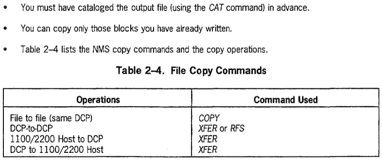
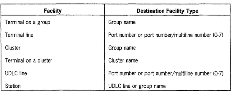
2-1. NMS Commands ... 2-2 2-2. Remote Node Network Address Identification ... 2-6 2-3. System Standard Qualifier Defaults . . . 2-16 2-4. File Copy Commands ... 2-41 2-5. MOVE Command Facility and Destination Types ... 2-127 2-6. File Copy Commands ... 2-143 2-7. UTS 60 Chart Titles and Labels ... 2-186 2-8. Telcon Software Debug Trace IDs ... 2-222 2-9. File Copy Commands . . . 2-240 2-10. NMS Command Error Messages ... 2-244
3-1. ILM Commands ... 3-4
)
4-1. 802.3 LAN LM NMS Commands ... 4-25-1. OSITS NMS Commands ... 5-2
6-1. TCP-IP Stack NMS Commands ... 6-2
7-1. File Copy Commands ... 7-3 7-2. Error Messages Defined by DDP ... 7-18 7-3. Warning Messages ... 7-20 7-4. Error Messages ... 7-21 7-5. IPC Class 3 Status Code Error Messages ... 7-22 7-6. IPC Class 4 Status Code Error Messages ... 7-23 7-7. IPC Class 10 Status Code Error Messages ... 7-24
,
01-0. IPC Class 128 Status Code Error Messages ... 7-24 7-9. IPC Class 129 Status Code Error Messages ... 7-25 7-10. IPC Class l30 Status Code Error Messages ... 7-26 7-11. IPC Class l31 Status Code Error Messages ... 7-26 7-12. IPC Class l32 Status Code Error Messages ... 7-27
8-1. CP Global ICW Bit Descriptions ... 8-5 8-2. lOP ICW Bit Descriptions ... 8-7
9-1. UCF Information for Documentation ... 9-5 9-2. DNS TRACE Commands ... 9-l3 9-3. Trace TypesjData Values ... 9-19
Tables
A-3. A-4.
)
About This Manual
Purpose
This reference manual is part of the operations subset of the DCP Series Telcon library. It explains the functions of the Telcon system.
The DCP Series Telcon network has three major software components:
• Telcon
• Communications Management System (CMS 1100)
• Distributed Communications Processor Operating System (DCP/OS)
This manual covers Telcon operations reference material only.
Scope
This manual addresses basic Telcon operations.
Telcon is a Unisys proprietary software product that processes transactions between a host and a DCP. Designed initially to support
as
2200 host computers, Telcon is based on the Distributed Communications Architecture (DCA). Telcon also serves as a platform support for Unisys program products and supports a variety of open systems communication protocols.DCA controls the Distributed Communications Processor (DCP), a major component of the OS 2200 system. In this manual, DCP refers to the DCP/5, 25, 30,35, 50, 200, or 600 unless stated otherwise.
This manual addresses the following Telcon operations:
• Telcon Network Management Services (NMS)
• Intelligent Line Module (ILM) NMS commands • 802.3 LAN Platform NMS commands
A L.. __ ... :_ .,, _____ I
I'1.UUU L • III., IWIGII UCII
• TCP-IP Stack NMS commands
• Remote File System (RFS)
• Instrumentation commands and messages
• CllST commands
• Software support procedures
Audience
This guide is for communication network operators, [systems] analysts, [systems] programmers, and others requiring a detailed description of NMS commands.
Prerequisites
This guide assumes the reader has advanced computer and communications understanding. It also assumes the reader has a basic understanding of Telcon software and DCA architecture.
How to Use this Manual
Commands are listed alphabetically within the following sections:
• Telcon NMS commands, with examples and descriptions (semantics) for each
• 11M NMS commands, with examples and descriptions (semantics) for each
• 802.3 LAN Platform NMS commands with examples and descriptions (semantics) for each
• OSITS NMS commands, with examples and descriptions (semantics) for each
• TCP-IP Stack NMS commands, with examples and descriptions (semantics) for each
• RFS commands used to transfer files in a DCP and Series 2200 network using Distributed Data Processing (DDP)
Systems analysts can use this manual to learn how to:
• Dump Telcon and analyze the results
• Write a User Communication Fonn (UCF)
Oiganization
This manual is divided into nine sections. Many sections contain quick-reference tables on the first page of the section. A glossary, bibliography, and index are included in the manual.
Section Description
About This Manual This section describes the purpose, scope, and notation conventions used to design the manual. This section also discusses the organization and additional product information.
Section 1 This section describes general NMS information Introduction pertaining to the location of specific NMS information,
NMS operating commands, and NMS command considerations.
Section 2 This section presents all NMS commands and their Network Management Services corresponding parameters and functions.
(NMS) Commands
Section 3 This section presents aU iLM NMS commands and their Intelligent Line Module (ILM) corresponding parameters.
NMS Commands
Section 4 This section presents all LAN Platform NMS commands 802.3 LAN Platform NMS and their corresponding parameters.
Commands
Section 5 This section presents all OSITS NMS commands and their Open Systems Interactive corresponding parameters,
Transport Services (OSITS) NMS Commands
Section 6 This section presents all TCP-IP Stack NMS commands TCP-IP Stack NMS Commands and their corresponding parameters.
Section 7 This section presents the commands used to request Remote File System (RFS) both local and remote file-related operations. This section Commands and Messages also lists and explains resulting messages. RFS
A ... _ ... a....:A' 1\11 ... 1
,",UVU!. • III;;:) IVIClI.IUal
Section Description
Section 8 This section presents NMS instrumentation commands
Instrumentation Commands and used to store the instrumentation buffers produced by the
Messages communications processor microcode. This section also lists and explains resulting messages.
Section 9 This section provides the instructions for logging a User
Software Support Information Communication Form (UCF).
Notation Conventions
This manual uses the conventions that follow to present command formats and other notations.
Notation Convention Example
Command formats Monofont Enter one of the following:
1. ABRT
PASS=name
2. ABRT PASS=name,PATH=n Command names ITALIC CAPS ABRT command
Descriptions Monofont Enter one of the following: Examples
1. ABRT
PASS=name
2. ABRT
PASS=name,PATH=n
Filenames italic Find the sp/ash.exe file in your directory.
Messages Monofont TRACE-TURNED ON
Parameters ITALIC CAPS ABRT PASS=name Parameter Values
Responses Monofont ABRT
PASS=name,PATH=n
Required keywords ITALIC CAPS The ABRT command terminates the specified
Telcon system and executes a Telcon dump.
About This Manual
Notation Convention Example
Screen displays Monofont Enter Command or Application number: 2
Statements ITALIC CAPS TYPE=ENTER MENU statement (Configuration or
Network Definition)
User entry bold italic Generation id? UTLGEN
Required Characters
You may need to use the following characters when entering a CMS 1100, Telcon, or DCP/OS command:
Character Description
Double colons ..
..
Separates some T elcon commands.I
Semicolons
,
Act as a continuation symbol when you continue a command on the next line. eMS 1100 commands usually require a space before thesemicolon; T elcon commands do not.
I
About This Manual
Command Conventions
The following conunand conventions are used in this manual:
Convention Reason for Use Example
Braces {} Encloses required parameters;
DEST=Jnn.nn.nn.nn
1
you must select one.tadr
1,adr2, adr3, adr4f
(Parameters not enclosed bybraces are also required.)
Brackets [1 Encloses optional parameters.
OS!
HELP[,command][,type]
Parameters may also appearstacked in the command syntax notation.
Braces within Enclose two or more optional
[ NODE= {
name
} ]
brackets [{} 1 parameters; you must select[[[n!]n!]n!]n
one of the parameters.
Parentheses () Encloses a list of parameters.
MOD=( NODR=n
)
One parameter from the list isLNKR=n, TRNK=name
required, however, more thanone or all of the parameters may be selected.
I
)
A hn'lf Thi ... 1\1I..:.l'u • ..:.1
... ..,.,..,w .. I II . . . "IIII4IIIWWI
Related Product Information
Documents are referenced in this manual using a shortened version of the title. To make it easy for you to find them in the table below, they are listed alphabetically by the shortened title, followed by the full title.
DocumentJPart Number Description
Buyer's Guide
to
DCP This guide provides marketing personnel and clients withCommunication Products detailed information about DCP hardware, software,
(74369828) networking connectivity, and product migration. It fills the gap between marketing brochures and technical manuals.
CMS 1100 Operations This manual provides operations information for the CMS
Reference Manual 1100 software. (7831 5694)
Communications Delivery The SRA describes new features, migration requirements, Software Release support, and ordering information. It also gives the content of
Announcement the release tape and specific ordering information. (74300088)
COMUS End Use This manual is a reference for using COMUS to install,
Reference Manual configure, and update OS 1100 software products on an OS (78307758) 1100 system. It describes COMUS commands and provides
examples of their use.
DCP lOS Operations This manual describes all DCP Operating System commands
Reference Manual and information. (7831 5702)
LAN Platform Configuration and This guide describes how to install and configure LAN Platform
Operations Guide software on a Distributed Communications Processor (DCP). It (7831 5512) includes an overview of the product, hardware and software
compatibility, descriptions of the required configuration statements, and examples of typical configurations. This guide also covers operations, with descriptions of the Network Management Services (NMS) commands, messages, and critical event notification and logging (CENLOG) procedures unique to LAN Platform.
OSITS Configuration and This guide describes how to install and configure OSI
Operations Guide Transport Services (OS ITS) software on a Distributed (7831 5587) Communications Processor (DCP). It includes an overview of
the product, hardware and software compatibility, descriptions of the required configuration statements, and examples of typical configurations. This guide also covers operations, with descriptions of the Network management Services (NMS) commands, messages, and critical event notification and logging (CENLOG) procedures unique to OSITS.
continued
DocumentjPart Number Description
TCP-/P Stack Configuration and This guide describes how to install and configure TCP-Ip
Operations Guide Stack software on a (DCP). It includes an overview of the (7831 5546) product, hardware and software compatibility, descriptions of
the required configuration statements, and examples of typical configurations. This guide also covers operations, with descriptions of the Network Management Services (NMS) commands, messages, and critical event notification and logging (CENLOG) procedures unique to TCP-IP Stack.
X.25 PSCS Configuration and This guide describes how to install and configure X.25 PSCS
Operations Guide software on a Distributed Communications Processor (DCP). It (7831 5470) includes an overview of the product, hardware and software
compatibility, descriptions of the required configuration statements, examples of typical configurations, and
information abo~rt the packet=svJitched netvJorks X.25 PSCS
Section 1
Introduction
Intrn~ll,..tinn
...
...,...
..,...
""'..
1 .. 1 NMS Information Included in This Book
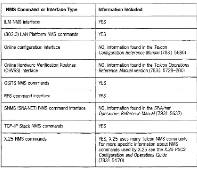
Table 1-1 describes the NMS information documented in this book.
Table 1-1. NMS Command Information
NMS Command or Interface Type Information Included
ILM NMS interface YES
(802.3) LAN Platform NMS commands YES
Online configuration interface NO, information found in the Telcon
Configuration Reference Manual (7831 5686)
Online Hardware Verification Routines NO, information found in the Telcon Operations
I
(OHVRS) interface Reference Manual version (7831 5728-200)
OSITS NMS commands YES
RFS command interface YES
SNMS (SNA-NET) NMS command interface NO, information found in the SNA/net
Operations Reference Manual (7831 5637)
TCP-IP Stack NMS commands YES
X.25 NMS commands YES, X.25 uses many Telcon NMS commands. For more specific information about NMS commands used by X.25 see the X.25 PSCS
Configuration and Operations Guide
)
1.2
Introduction
NMS Operating Information
The following subsections describe attributes common to all types of NMS commands used in this book.
For more detailed information on NMS concepts, see the Telcon Operations Guide
(7831 5785).
1.2.1 Entering Network Management Services
Step Action
l. Enter the $$OPEN command from any Telcon UNISCOPE@ or DCA type terminal. (See
.""' ... T ... J ... C' ... ,.J I I ... 1"'. ,:...1 ... r7,., ~c:. (Y'7':1£:1 .,f.,... : ... oh-... : ... t.. ... , ... "' ... "'&... ... CCf"'lDCf\.1
lilt:: ICJl,..UI' LIIU u~c::: UUIUC l/41"";U V/..JUJ IVI III':'UU\, .. UUII':' UII liUVV lV ClllCI lilt: ..)..;>V[ '-''f
command.) After the $$OPEN command executes, your screen displays a two-line
heading. Line 1 displays the Telcon product name, Telcon system level number, DCP PRCSR name from your configuration file, and the level number of your configuration if
your configuration specifies a configuration number. Line 2 contains a row of dashes separating the heading information from the rest of the screen. Lines 3 to 22 are blank. Line 23 contains a start-of-entry (SOE) character. NMS positions the cursor following the SOE.
Introduction
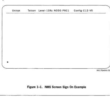
Figure 1-1 shows the NMS screen.
Unisys Telcon Level-lORx NODE-PRCI Config-C12-V5
L·
001 TG400.CDRJ
Figure 1-1. NMS Screen Sign On Example
Explanation
level-10Rl
Define the level when generating Telcon using COMUS. This level is the same as reported with the NMS STAT and SST commands.
NODE=PRCI
Define the DCP name in the configuration using the processor configuration statement. Config-C1 2-V5
)
Introduction
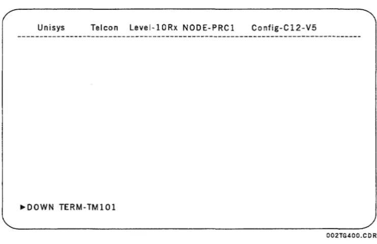
Figure 1-2 shows an example of an entered command. The command has not been transmitted.
Unisys Telcon Level-lORx NODE-PRCl Config-Cl2-V5
TERM-TMIOI
J
002TG400.CDR
Intrnrh ,,.tinn
. . . 1WI' . . . 1I
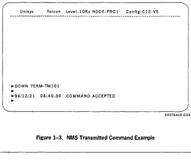
Figure 1-3 shows a command example and response after input. The DOWN command
has been transmitted.
Unisys Telcon Level-lORx NODE-PRCl Config-Cl2-V5
~DOWN TERM- TM 1 01
~
~94!12/2l 08:40:30 COMMAND ACCEPTED
~
Figure 1-3. NMS Transmitted Command Example
1.2.2 NMS Command Formats
Format
You must be familiar with the following NMS command fonnats before you can enter NMS commands properly.
The following illustrates a sample NMS command fonnat.
I
T
{DVC= name
}I
' FI LE=
name
name
CNCL FUNC= M
[,NODE={[[[nIJnIJnIJn}]
X.XFER)~l
l . 1~ J J
Explanation
CNCL
The command name is always entered first.
FUNC=
D~"':::lIrn.o.+o.,.C' <::11"0. an+ororl i""r"r"I.o.rli<::lfal\l "!Ioffn.V' +ho I""1"'\"""''''''''''=lInri n"':ll"""'''''' ~..,rI """"1"'11 hJ"\ ,..."".f.,... .. "rI i.." ... n' ... A"" ...
I ""1~III""L\"OI..;) U.\.; \".0111.\,,01 \,,\..1 UIIIII\:;;;iUIULvl)' ""Lvi "'llv ,",VIIIIIIUIIU IIQIIIt:;;, ailU \...QII LIt; 'C::tll'CIt:;U III Gilly UIUt::1 unless stated otherwise.
{}
Braces indicate a list of parameter choices. You must choose one. []
Biackets of any size indicate optional paiameteis.
[{}]
Braces within brackets enclose two or more optional parameters. You may choose one of the parameters.
liitioductioii
Example NMS command entries
1. CNCL FUNC=T. DVC=pat32
2. CNCL FUNC=X. XFER=2. NODE=prc1
NMS Prefixes and interlace Commands
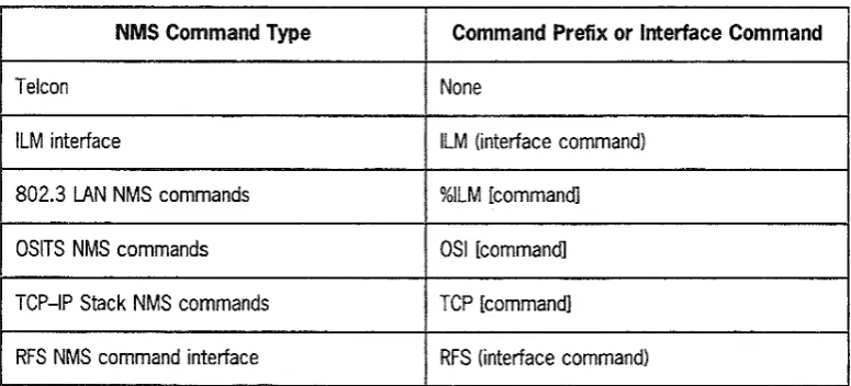
You must specify some types of NMS commands with a prefix or by entering a program product NMS interface. Table 1-2 shows command prefixes or interface commands used to enter specific commands included in this document.
Table 1-2. NMS Command Prefixes and Interface Commands
i i i
NMS Command Type Command Prefix or Interface Command
Telcon None
ILM interface ILM (interface command) 802.3 LAN NMS commands %ILM [command] OSITS NMS commands OSI [command] TCP-IP Stack NMS commands TCP [command]
RFS NMS command interface RFS (interface command)
You can also specify which Telcon node to which you want to direct the NMS
command by using the following parameter after the command or interface command:
{
name
}
NOOE=.[[[nl]nl]nl]n.
The NODE parameter is optional for most commands. This parameter specifies the name of the Telcon node or network address where the command will be executed. If you omit the NODE parameter, NMS directs the command to the Telcon node to which your console is logically connected. See Section 2.2 of
NMS Command Rules
II Ignore spaces and special characters before the command word.
II Parameters can appear in any order following the command word, unless
otherwise specified.
II You can replace the comma and the equal sign with a space to separate
parameters or parameter arguments. For darity in this document, a comma is
shown between the parameters and an equal sign is shown between the parameter identifier and its argument.
II Either uppercase or lowercase letters are acceptable.
II Parameter values are no more than eight characters long, unless stated otherwise.
G Numbers are denoted by ·n. Each base of the number has a different format as follows:
A decimal starts with a single number, such as 101. A hexadecimal starts with a leading zero, such as 0101.
An octal starts with a leading letter 0' and ends with a single quote, such as 0'101'.
A binary starts with a leading letter B, with the numbers following the B in single quotes, such as B'IOI'.
II Most commands can be abbreviated. However, use parameter abbreviations with
caution. If you receive a message that a cornmand is rejected, undefi...ned, or if you
receive unexpected results or responses, then reenter the command without parameter abbreviations.
All command abbreviations appear in parentheses following the command name on the page header. For example:
STAT(S)
or
COpy (CO)
If a command is not abbreviated in the page header, there is no
abbreviation for that command and you must enter the whole command name. For example:
ABRT(ABRT)
or
)
Section 2
Network Management Services (NMS)
Commands
This section describes NMS conunand attributes, including:
011 Definitions
011 Fonnats
011 Required parameters
011 Optional parameters
011 Examples
011 Responses
011 Explanations
Note: The headings at the top of each page show the full name of the NMS
command folkJwed, in parentheses, by an abbreviated form of the command
name. You can use the abbreviated form of the command name
to
execute the2.1
NMS Command Index
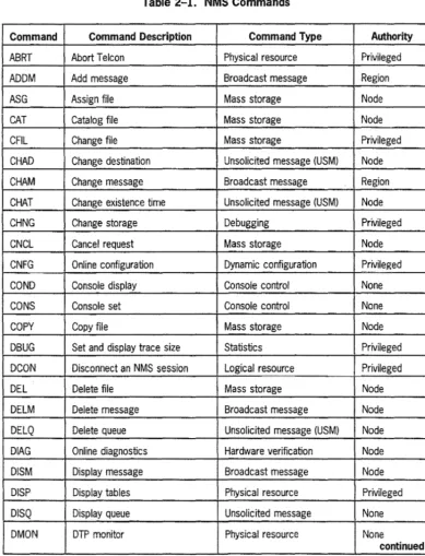
Table 2-1 provides an alphabeticailist of NMS commands for easy reference to this
section. The mnemonic, description, type and minimum authority required for execution are presented for each command. See the Telcon Operations Guide
(78315785) for an overview of NMS.
Table 2-1. NMS Commands
Command Command Description Command Type Authority
ABRT Abort T elcon Physical resource Privileged
ADDM Add message Broadcast message Region
ASG Assign file Mass storage Node
CAT Catalog file Mass storage Node
CFIL Change file Mass storage Privileged
CHAD Change destination Unsolicited message (USM) Node CHAM Change message Broadcast message Region CHAT Change existence time Unsolicited message (USM) Node
CHNG Change storage Debugging Privileged
CNCL Cancel request Mass storage Node
CNFG Online configuration Dynamic configuration Privileged COND Console display Console control None
CONS Console set Console control None
COpy Copy file Mass storage Node
DBUG Set and display trace size Statistics Privileged DCON Disconnect an NMS session Logical resource Privileged
DEL Delete file Mass storage Node
DELM Delete message Broadcast message Node DELQ Delete queue Unsolicited message (USM) Node DIAG Online diagnostics Hardware verification Node DISM Display message Broadcast message Node DISP Display tables Physical resource Privileged
Network Management Services (NMS) Commands
Command Command Description Command Type Authority
DMOR DTP monitor Repeat Physical resource None DOWN Bring facility down Physical resource Region
DTRC DNS trace Physical resource None
ENS Enterprise Network Services ENS Privileged
FRE Free file
I
Mass storage NodeHELP Help Help None
IDEN Identity Console control None
ILM Intelligent Line Module (ILM) ILM Privileged INIT Initialize DNS trunk Physical resource Privileged
iNS-P inspect memory Debugging
I
PrivilegedI
ISDM Initialize standard message file Broadcast message Region ITLN Initialize line Physical resource Region LCHG List change numbers Miscellaneous None LIST List configuration data Physical resource Privileged
)
LOGC Logging change Logging/statistics NodeLOGD Logging display Logging/statistics None LOGI Logging inspect Logging/statistics Privileged LOGR Logging restrictions Logging/statistics Privileged MOD Modify DNS network parameters Physical resource Privileged MOVE Move facility Physical resource Privileged MOVS Move facility Physical resource Privileged
MSG Message Miscellaneous Node
MSWT Matrix switch Physical resource Privileged NMSB Console display Console control None
ONLN Online Resiliency Privileged
QUIT Disconnect the NMS console Logical resource None session
RCVR Recover Physical resource Node
RESL Resiliency Resiliency Node
REST Restart T elcon without a dump Physical resource Privileged
Network Management Services (NMS) COmmands
Command Command Description Command Type Authority RFS Remote file system Remote file system (OOP) Privileged RMOV Resilient line move Physical resource Privileged SONS Status of ONS network Physical resource None
parameters
SECi initiaiize Security Facility
I
Security Privileged SECL List facilities in the Security Security PrivilegedManagement Information Base (SMIB)
SET Set time and date Physical resource Privileged SETI Set time and interval Statistics Node SNDM Send message Broadcast message Region
SST Short status Physical resource None
STAR OCP status repeat Physical resource None STAT Facility status Physical resource None
STBY Standby Resiliency Privileged
STOP Stop input/output Physical resource Region STOR Local storage Physical resource None STRT Start input/output Physical resource Region STIH Set error logging threshold Physical resource Node
SWT Switch Resiliency Node
TEST Test UOLC line Physical resource None TEXT Text attributes Console control None
TROF Trace off Statistics None
TRON Trace on Statistics Node
UP Bring facility up Physical resource Region UPOT Update ONS network Physical resource Privileged
parameters
XCMO External command Physical resource None XFER Transfer file from host to OCP or Mass storage Privileged
2.2
Format
NODE Parameter
This subsection describes the NODE parameter. The NODE parameter is included in the format of many commands described in this manual.
The NODE= parameter functionality has been expanded to include configuration statements, previously known as Network Definition Statement (NDS) types. The following configuration statements have been included in the NODE= parameter:
PRCSR, ADDRESS, NETADR, and XEU, in addition to an explicit DNS network
address. See the Telcon Configuration Reference Manual (7831 5686) for detailed information on NDS types.
You may use the NODE parameter (when allowed) to direct NMS command input to any desired destination in the network.
You may abbreviate the NODE= parameter to N.
={
name }NODE- [[[n!]n!]n!]n
Explanation
NODE=name
Is the T elcon node name unit mnemonic on which the command executes. The default is the Telcon node to which your console is logically connected.
NODE=[[nj]nj]nj]n
Is the network address of a remote DNS node. The first number specifies the subdomain number, the second number specifies the super cluster number, the third number specifies the simple cluster number, and the fourth number specifies the node number. Valid ranges are:
• The subdomain number range is from 1 to 65,535. The default is the local subdomain number.
• The super cluster range is from 1 to 255. The default is the local super cluster number.
• The simple cluster range is from 1 to 255. The default is the local simple cluster number.
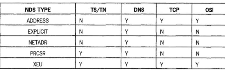
For NODE=n, you may omit the subdomain, supercluster, and simple cluster component parts of the network address. Any omitted component parts default to the network address component parts of the network address of the Telcon node to which you are logically connected. Table 2-2 shows which NDS types are used to identify each type of remote node.
Note: For the NODE parameter in a TS/TN environment, you must use the NODE=name format.
Table 2-2. Remote Node Network Address Identification
NDS TYPE TSjTN DNS Tep 051
ADDRESS N Y Y Y
EXPLICIT N Y N N
NETADR N Y N N
PRCSR Y Y N N
2.3
NMS Commands
2.3.1 ABRT -
Abort Telcon
Format
The ABRT command terminates the specified Telcon system and executes a Telcon dump.
1. ABRT
PASS=name
2. ABRT
PAss=name[.Rcw=n][.NODE={[[[~/Jnl]nIJn}]
Required
Parameters
PASS=name
Is the NMS password for the node to be terminated.
Optional
Parameters
RCW=n
Is used to set the run condition word (RCw). The range for
n
is O-FF. The default is O.{
name
}
NODE=
[[[nIJnIJn/Jn
)
ABRT (ABRT)
Example
ABRT
PASS=PA T123Response
1994/07/24 15:55:17
•••
Warning:NMS ABRT COMMAND RECEIVED FROM:
••• CONSOLE ID
=PU1CON
••• NODE 10
=PRC1
Note: This message is displayed on aU NMS active consoles tlwt are logicaUy attached to the Telcon node being aborted. In addition to this message, a
similar message is sent to the DCP/OS console.
Additional Discussion
If you use the standard T elcon runstream, the first result of executing the ABRT command is that a
Telcon dump is sent to DCP mass storage. The Telcon runstream then specifies the subsequent T elcon absolute and configuration file to execute, based on the path you entered to set the run condition word (RCW). See the T elcon runstream on your OS 2200 host in the standard T elcon source control files (sym, pcf, and reO. The runstream is copied to the sysS'sysjob file on the OCP
during the download host load phase. See the DCP/OS Operations Reference Manual (7831 5702)
for more information.
If you are running the standard Telcon runstream, the sysS'sysjob implements the following executions:
• RCW=O Default • RCW=l
Executes *TELCON.TELCON with *CONFIG. • RCW = 2
Executes *TEST.TELCON with *CONFIG.
II RCW = 3
Executes *TELCON.TELCON with NEW*TSTCFG. The following OCP lOS system utilities can interrogate the RCW:
• @IF
• @ELSE
• @ENDIF
• @RCW
The @RCW command can also alter the run condition word. For a detailed description of these
2.3.2 ADDM - Add Broadcast Message
The ADDM command inserts a new broadcast message.
Format
ADDM NUM=n
text
Required Parameters
NUM=n
Is the message number.
text
Is the message text, including carriage returns; 240 character maximum.
Optional Parameters
Example
None.-ADDM NUM 1
THIS
MESSAGE
IS
NOT
LONGER
THAN
240
CHARACTERS
Response
1994/07/24 12:15:37 ADDED MESSAGE
)
ADDM (ADj
Example
ADDM NUM=7 THE DCP WILL BE REBOOTED AT 8PM
Response
1994/07/24
12:20:56 ADDED MESSAGE
7 THE DCP WILL BE REBOOTED AT 8PM
Considerations
• Do not end a line with trailing blanks (spaces). Different terminal types transmit different input and blanks may cause unexpected results.
• To put trailing blanks on a line, enter the blanks and then put an alphanumeric character at the end.
ASG (Aj
2.3.3 ASG - Assign Tape File
Format
The ASG conunand specifies physical tape file attributes. The tape system uses the attributes to locate and access user files. You must assign a tape file before a user program can complete an open request for the file.
1. ASG FILE=name
2. ASG FILE=name[.LTYP=type][.SKIP=n][.DNSY=density][.VOL=name/ ... ]
[.NODE={~~f~/Jn/]n/]n}]
Required Parameters
FILE=name
Is the name of the user-specified tape file.
Optionai Parameters
LTYP=1ype
Indicates label type of the tape. Values include:
I Standard labels are skipped during positioning and not processed by the tape system. L Standard labels.
U Unlabeled tape (default).
IS Scratch tape with standard labels; they are skipped during positioning and not processed by the tape system.
LS Scratch tape with standard labels. US Unlabeled scratch tape. The default is US. SKIP=n
Is the number of files skipped before the subject file on the first or only tape volume.
ASG fA)
DNSY=density
Specifies the recording density of the tape. It can be:
H 1600 bps
L 800 bps The default is H.
This parameter is effective oniy for output tapes written from ioad point. in aii other cases, hardware from the existing data at the beginning of the tape determines the density. VOL=name
Specifies the volumes on which the file resides. You can specify up to eight volumes for a file. The maximum length of a volume name is six characters.
For multiple volumes, each volume ID is separated by a slash (j).
VOL must be specified unless the LTYP value is IS, LS, or US.
fname }
NODE1[ [[
n/] n/J n/J nSee Section 2.2 of this manual for a description of the NODE parameter.
Note: The current level of the tape system does not process tape labels; therefore, the parameter
values Land LS have the same effect as I and IS.
Example
ASG FILE=KATE
Response
2.3.4 CAT - Catalog a File
Format
The CAT command catalogs a file (which is assigned a name by the command) on mass storage.
• VOL=name DSKR
{ I
~Kname IFDC
CAT FILE=
*nam~ . .SIZE=n DTYP- FDDSqua77f7e~name SCS
SCSD
[
.{NODEi~fr~1]
nl] nl] n}j]
XTS=namel
1.
CATFILE={~~;!e
I
qua 7 i fi e~name
2.
CAT
FILE={~~;!e
1[.SIZE=n{.~ToYL~=name}]
qua7ifie~name • name
{
name }
FI LE= *name
qua 7 j f j ett-name
CAT (CA)
"'name
Is the basic name of the file with the default qualifier; eight character maximum, including a-z, 0-9, -, and $. Refer to Table 2-3.
qualifier
Is the qualifier that establishes the uniqueness of the file name, six character maximum, including a-z, 0-9, -, and $. Refer to Table 2-3.
Optional Parameters
SIZE=n
Is the number of 256-byte blocks to allocate on mass storage for this file. The default size is 128 blocks.
VOL=name
Is the name of the volume of which the file is a portion; six character maximum. The default is any available volume.
DTYP=name
Is the type of mass storage device on which you want to catalog your file. Valid types are as follows:
DSKR
DSKF
IFDe
FDDS
SCSW
SCSD
WDSK
RAMD
Removable cartridge disk Fixed cartridge disk Integrated diskette Double-density diskette
Winchester 8441 disk or controller mass storage (8441jintegrated DCP /15 and 50 mass storage) Type 8441 diskette
Winchester 8409 disk RAM disk
,..I1T
',..11 \
"'...
,"'''/
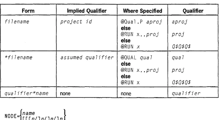
Table 2-3 lists the system standard qualifier defaults.
Table 2-3. System Standard Qualifier Defaults
Form Implied Qualifier Where Specified Qualifier
filename
project id
@Qual ,P
aproj
aproj
else
(,;lDII" x, ,proJ
proj
'!::!'j"\UI'(
else
@RUN
x0$0$0$
*fi
Iename
assumed qualifier
@QUAL
qua7
qua7
else
@RUN x,
,proj
proj
else
@RUN x
0$0$0$
qua
Iifier*name
I
noneI
nonequa7ifier
{
name
}
NODE=
[[[n/Jn/Jn/Jn
See Section 2.2 of this manual for a description of the NODE parameter. XTS=name
Indicates the name of an external termination system. VOL and DTYP are mutually exclusive.
Examples
Example 1
CAT FILE=UNIQUE,VOL=MOND,SIZE=100,NODE=FEPB
Response
1994/07/24
11:24:34 CATALOG COMPLETE
Example 2
CAT FILE=TELFIL
CFll (CFj
2.3.5 CFIL - Change File
Format
The CFIL conunand causes Telcon to switch from the current configuration file to a
new file under the following conditions:
• You can open the specified file
• You can validate the specified file as a Telcon configuration file
• All currently active facilities exist in the new file
After executing the CFIL conunand, all subsequent internal configuration access
requests use the new file for the duration of the Telcon program execution, or until the next CFIL command execution. When using the CFIL conunand, specify the same
file name that you previously specified on one or more CNFG (online configuration)
commands. See the Telcon Configuration Reference Manual (7831 5685) for
information about the C'NFG command.
Notes:
1. You can use the CFIL command only with a file that has been created or
modified through online configuration.
2. CFIL switch processing requires that all facilities in the old file exist in the new
file by the same name, type, and order.
If
not, the file switch aborts and displaysthe facilities in question. Either add the facilities to the new file or mark them
inactive (DOWN) in the old file. You can only insert facilities at the end of the
old file configuration.
3.
If
you added an XEU, NETADR, or INN parameters and you are running DSF(RUNID=DSA), the additions wiU not be in the DSF directory.
1.
CFILFILE={~~~~e
}qua
7i fi efJname
CFIL (CFj
Required Parameters
FILE=
name
Is the basic name of the new configuration file. Refer to Table 2-3.
*name
Is the basic name of the file with the default qualifier; eight character maximum, including a-z, 0-9, -, and $. Refer to Table 2-3.
qualifier
Is the qualifier that establishes the uniqueness of the file name; six character maximum, including a-z, 0-9, -, and
$.
Referto
Table 2-3.Note: You must use the name parameter when you name a file. You can optionally use the "name
or qualifier*name parameters to designate the filename. The system provides defaults for
omitted parameters, as described in Table 2-3.
Optional Parameters
{name }
NODE=
[[[nl]nl]nl]nSee Section 2.2 of this manual for a description of the NODE parameter. XTS=name
Example
Indicates the name of an external termination system as defined by a DeATS configuration statement.
CFIL FILE=BILL
Response
CFll (CF)
Additional Discussion
CFIL processing tests for the following conditions:
• Non-existent file • Non-configuration file • Missing active facilities • Same file
If the file you specify is the same as the current file, no switch occurs and an error message is displayed. If any OCP/OS file-access error results from opening, reading, or writing to the new file, the switch is aborted and an error message is displayed to reflect the OCP lOS file-access error. See the DCPjOS Operations Reference Manual (7831 5702) for more information about file-access codes.
When the CFIL command successfully completes, the following operator display message (using PRC1 as an example) displays on you console:
1994/07/24
13;02;16 ***DCP= PRC1 SYSTEM INITIALIZATION COMPLETE
(This message is not displayed if a CONS command indicates you have not turned on your OPDS
messages.)
Some of the changes or additions you made to this new file by using online configuration become effective immediately after the CFIL command is processed (unless the facility is marked DOWN).
Other changes do not take effect until T elcon is forced to access the configuration file for a changed statement, such as through an UP, DOWN, ITLN, or SS command. See the Te/con End Use Guide
(74360736) for descriptions of the SS commands. Some other changes do not take effect until T elcon restarts with the new configuration file specified in the T elcon runstream.
When Telcon restarts, it uses the file your runstream specifies. If you want Telcon to restart with the new switched file, edit your Telcon runstream to change the file specification on all appropriate
@TELCON processor call statements. See the DCPjOS Operations Reference Manual (7831 5702)
for information about the @£D commands.
If you allow T elcon to restart with the default T elcon runstream, T elcon uses the runstream that exists on the OCP in file sysS'sysjob in element TELCON. See the Telcon Installation Guide (7831 5645) for
2.3.6
CHAD - Change USM Destination
The CHAD command changes the destination of unsolicited messages (USMs).
Format
1. CHAD
FROM=name.TO=name
2. CHAD
FROM=name.TO=name[.MSG=name][.ORIG=name]
Required Parameters
FROM=name
Identifies destination; original (TERMINAL/SITE name) destination of the queued messages.
TO=name
Identifies destination; new (TERMINAL/SITE name) destination to which messages are queued.
Optional Parameters
Example
MSG=name
Identifies the message to be moved. Default is all queued messages.
ORIG=name
Identifies terminal of message sender. Default is all senders.
CHAD FROM=PU1 CON,TO=PU3CON
Response
1994/07/24
10:48:57 CHAD COMPLETE
MESSAGES QUEUED TO TERMINAL PU1CON
EMPTY
MESSAGES QUEUED TO TERMINAL
CHAM (CHAM)
2.3.7 CHAM - Change Broadcast Message
The CHAM command replaces an existing broadcast message in the file s@stdmnn with a new message. (Also see the ISDM command later in this section.)
Format
CHAM NUM=n
text
Required Parameters
NUM=n
indicates number of the message you want to change.
text
is the message text, including carriage returns; 240 character maximum.
Optional Parameters
None
Example
CHAM NUM=l TODAY IS FRIDAY AUGUST 2
Response
1994i07i24
09:37:12 NEW STANDARD
Mt~~AGtI " U " 11111 I I " U " 11111\