Volume 2009, Article ID 231587,15pages doi:10.1155/2009/231587
Research Article
Space-Frequency Block Code with Matched Rotation for
MIMO-OFDM System with Limited Feedback
Min Zhang,
1Thushara D. Abhayapala,
1Dhammika Jayalath,
2David Smith,
3and Chandra Athaudage
41College of Engineering & Computer Science, Australian National University, Canberra, ACT 0200, Australia 2Faculty of Built Environment & Engineering, Queensland University of Technology, Brisbane, QLD 4001, Australia 3National ICT Australia Limited, Canberra, ACT 2601, Australia
4Department of Electrical & Electronic Engineering, University of Melbourne, Melbourne, VIC 301, Australia
Correspondence should be addressed to Thushara D. Abhayapala,[email protected] Received 30 November 2008; Revised 19 April 2009; Accepted 24 June 2009
Recommended by Markus Rupp
This paper presents a novel matched rotation precoding (MRP) scheme to design a rate one space-frequency block code (SFBC) and a multirate SFBC for MIMO-OFDM systems with limited feedback. The proposed rate one MRP and multirate MRP can always achieve full transmit diversity and optimal system performance for arbitrary number of antennas, subcarrier intervals, and subcarrier groupings, with limited channel knowledge required by the transmit antennas. The optimization process of the rate one MRP is simple and easily visualized so that the optimal rotation angle can be derived explicitly, or even intuitively for some cases. The multirate MRP has a complex optimization process, but it has a better spectral efficiency and provides a relatively smooth balance between system performance and transmission rate. Simulations show that the proposed SFBC with MRP can overcome the diversity loss for specific propagation scenarios, always improve the system performance, and demonstrate flexible performance with large performance gain. Therefore the proposed SFBCs with MRP demonstrate flexibility and feasibility so that it is more suitable for a practical MIMO-OFDM system with dynamic parameters.
Copyright © 2009 Min Zhang et al. This is an open access article distributed under the Creative Commons Attribution License, which permits unrestricted use, distribution, and reproduction in any medium, provided the original work is properly cited.
1. Introduction
A multiple-input multiple-output (MIMO) communication system has an increased spectral efficiency in a wireless channel. It can provide both high rate transmission and spatial diversity between any transmit-receive pair. The appropriate space time block code (STBC) allows us to achieve, or approach, channel capacity for the flat fad-ing propagation channel with multiple antennas [1–4]. Moreover, an orthogonal frequency division multiplexing (OFDM) system transforms a frequency selective fading channel into a number of parallel subsystems with flat fading. It can eliminate the inter symbol interference (ISI) completely by inserting a long enough cyclic prefix (CP). The MIMO-OFDM system has attracted much attention for future broadband wireless systems and has already been implemented in IEEE802.11n, WiMax [5] and 3G-LTE systems [6,7].
For MIMO-OFDM systems, various space-time/ frequency codes have been developed to achieve spatial, multipath, and temporal diversities by coding across multiple antennas, subcarriers, and OFDM symbol intervals [8]. All existing STBCs, for example, [1, 9, 10], can be converted into space-frequency block codes (SFBCs) simply by spreading the time domain signal of STBC within the frequency domain. This conversion works well if adjacent subcarrier channels are highly correlated, for example, Alamouti code [1] proposed to be deployed within the LTE system [6]. However this kind of direct conversion [11] is not optimal and fails to achieve valuable frequency diversity that can improve system performance.
order where L is the fixed channel order (the number of paths) and Nt is the number of transmit antennas. The channel order provides an upperbound in the rank of the frequency correlation matrix of the OFDM system [15]. Hence by employing more than a threshold number of subcarriers, full spatial and frequency diversities can be achieved. However the channel orderLmight be large, for example, L+ 1 = 20 in [16], and vary with users and scatterer movement, raising questions about the practical implementation of these SFBCs.
On the other hand, the design of SFBC provides a fundamental understanding so that a variety of space-time-frequency block codes (STFBCs) are proposed for particular system requirements and channel conditions. Essentially these STFBCs do not differ significantly from either SFBC or STBC. Some STFBCs have assumed that consecutive OFDM intervals are static during a period of time. For example, a rate one STFBC is proposed in [17] by combining orthogonal STBC [18] and linear dispersion codes [9, 19], and also proposed in [20,21] using quasiorthogonal block codes [22]. Alternatively some STFBCs have assumed that consecutive OFDM intervals are independent (or slightly correlated) during a period of time so that temporal diversity could be achieved. For example, the rate one STFBC proposed in [23] extends SFBC in [13] into all space, time, and frequency domains. High rate full diversity STFBCs are proposed in [24,25] using a layered algebraic design.
The SFBC proposed in [12,23] does not require knowl-edge of the channel power delay profile (PDP) at the transmit end. However it is verified only for specific channel condi-tions and provides an upperbound of performance so that the diversity lose may happen. To overcome this problem and also optimize the system performance, perfect knowledge of channel PDP is required by the transmit antennas in the optimization process proposed in [13] and further high rate SFBC design proposed in [24,25]. Such an assumption might not be feasible for a practical implementation. Moreover, the optimization process proposed in [13] adjusted the subcarrier interval to improve the performance. But the optimal subcarrier interval might not be a factor ofNcwhere
Ncis the number of subcarriers of a MIMO-OFDM system.
Hence partial subcarriers of the system cannot achieve such optimal subcarrier interval after grouping. Furthermore, a MIMO-OFDM system is usually divided into a number of MIMO-OFDM subsystems by subcarrier grouping. In a multiuser scenario each user will be allocated one or more subsystems. This property leads to diverse optimal subcarrier intervals for different subsystems and users. Then a new problem of subcarrier grouping is raised since all users in the system will compete with each other to get a better allocation of subcarriers.
Because of relatively large channel order in real propaga-tion scenarios, achieving full space and frequency diversity is not a top priority but how to achieve a given transmit diversity order efficiently across both space and frequency domains is a more important question. Moreover, consider-ing the difficulty in realization of full knowledge of channel PDP at the transmit end, and the limitation of optimization for subcarrier interval, a novel matched rotation precoding
(MRP) is proposed in this paper. At first, the basic structure and design criteria of SFBC demonstrate the repetition and rotation patterns, which do not exist in the traditional STBC design. Moreover, the proposed SFBC design structure focuses on the scenario of partial knowledge of channel PDP known by the transmit antennas through the link feedback. Then a rate one MRP and a multirate MRP are proposed, both of which are capable of achieving full transmit diversity for the MIMO-OFDM system with an arbitrary number of antennas, subcarrier interval, or subcarrier grouping. The rate one MRP has a relatively simple optimization process, which can be transformed into an explicit diagram. The optimal rotation angles of MRP can be derived explicitly, or even intuitively in some cases. On the other hand, the multirate MRP has a more complex optimization process but has better spectral efficiency than the rate one MRP. Hence a better performance can be achieved by the multirate MRP if the same bit transmission rate is assumed. It is also capable of achieving a relatively smooth balance between system performance and transmission rate without significantly changing the coding structure.
The rest of the paper is organized as follows. Section2
describes a model for the MIMO-OFDM system and reviews the correlation structure between space and frequency domains. Section 3 presents design criteria of SFBC and reveals the distinct repetition and rotation patterns. Design structures for scenarios with full or limited knowledge of PDP are also compared and investigated in this section. Then Section4introduces a rate one MRP with limited feedback knowledge and corresponding optimization process. And Section5introduces a multirate MRP with limited feedback knowledge and corresponding optimization process. Sec-tion6provides simulation results, and Section7concludes the paper.
Notation 1. Matrices and vectors are denoted by boldface letters. The (·)T, (·)∗, and (·)†are defined as matrix trans-pose, complex conjugate, and adjoint of complex conjugate transpose, respectively. The process of “vec” is defined as a matrix reconstruction which stacks a matrix columnwise to form a column vector. ⊗ and ◦ are defined as Kronecker product and Hadamard product, respectively.1aand1a×bare defined asa×aanda×ball one matrices, respectively.Iais defined as ana×aidentity matrix.
2. MIMO-OFDM System Modelling
2.1. Subcarrier Grouping for the MIMO-OFDM Model. We consider a MIMO-OFDM system withNttransmit antennas,
Nr receive antennas and Nc subcarriers. The frequency
selective channel is assumed to be static (timeinvariant) within at least one OFDM symbol intervalTs. Each transmit and receive pair hasL+1 resolvable delay paths with the same PDP, for example, SCM [26] and COST207 [27]. A block of data symbols is transmitted over each transmit antenna and passed through aNc-point inverse fast Fourier transform and followed by the appending of a CP. The length of CP is chosen to be long enough to remove the ISI completely. At each receive antenna the CP is removed at first and then a fast Fourier transform is applied. Hence the MIMO frequency selective fading channel is decoupled intoNcparallel MIMO flat fading channels.
To reduce system complexity while preserving both diversity and coding gain, a MIMO-OFDM system typically is partitioned into Ns MIMO-OFDM subsystems where
Ns ≥ 1. It is pointed out in [28] that the MIMO-OFDM system capacity with grouping can approach the channel capacity without grouping very closely. Hence the performance of the system is evaluated by the averaged performance of all subsystems. Here we consider a subsystem with P subcarriers selected from a total of Nc subcarriers where P is an arbitrary integer greater than Nt. The subcarriers in the subsystem are equally separated from each other with a positive integer interval δ. The optimization process by tuning subcarrier interval δ was proposed in [13]. However due to the limitations of implementation, the subcarrier interval δ is fixed in a MIMO-OFDM subsystem in this paper. Therefore, it is assumed that
δ = Nc/P where a denotes the largest integer less
than or equal to a so that the subcarriers are separated as far as they can be in the subsystem. The rest of (Nc −
δP) < P subcarriers could be used as guard intervals to separate OFDM symbols. Then a MIMO-OFDM system is partitioned into Ns = δ MIMO-OFDM subsystems who preserve exactly same second order characteristics. Hence the proposed SFBC design only focuses on an arbitrary MIMO-OFDM subsystem. For a multiuser scenario, each user can be allocated one or more MIMO-OFDM subsystems depending on the system complexity and requirement. The block diagram of a MIMO-OFDM system is shown in Figure1.
The channel frequency responsehmn(p) over thepth sub-carrier in the MIMO-OFDM subsystem between transmit antennamwhere (m ∈ [1,. . .,Nt]) and receive antennan where (n∈[1,. . .,Nr]) is given by
hmnp= L
=0
mn,e−j2π((p−1)δ+1)τ/Ts, (1)
where p ∈ [1,. . .,P] and ∈ [0,. . .,L], τ and mn,
are the delay and complex amplitude coefficient of theth path, respectively, and Ts is the OFDM symbol interval. The channel frequency response between transmit and
receive antennas for thepth subcarrier in the MIMO-OFDM subsystem is denoted by
Hp=
⎡ ⎢ ⎢ ⎢ ⎢ ⎣
h11
p · · · h1Nr
p
..
. · · · ...
hNt1
p · · · hNtNr
p ⎤ ⎥ ⎥ ⎥ ⎥
⎦, (2)
where each entryhmn(p) is given by (1). Then thePNt×Nr
channel matrixHis constructed by stacking up these channel matricesH(p) columnwisely and shown as
H=H(1)T,. . .,H(P)TT. (3)
Suppose that the transmitted symbol vectorSis defined asS =[s1,1,. . .,s1,Nt,. . .,sP,1,. . .,sP,Nt] where two subscripts
denote specific subcarrier and transmit antenna, respectively. Moreover, the transmission power of vectorSis normalized within each SFBC design and each MIMO-OFDM subsys-tem. It is given byE[SS†] = P. Hence the receive signal of each subsystem, aPNr×1 vectorY, can be expressed as
Y=
ρ NtSvec
H+Z, (4)
where S = {(INrP⊗11×Nt)◦(1NrP×Nr ⊗S)}. The channel
state information H is assumed to be perfectly known at the receive end, but not known at the transmit end.ρis the average signal to noise ratio (SNR) at each receive antenna, independent of the number of transmit antennas and receive antennas. The noise vectorZis assumed to be additive white Gaussian noise with zero mean and unit variance.
2.2. Correlation Structure of the MIMO-OFDM Subsystem.
The MIMO-OFDM subsystem is assumed to have arbitrary spatial correlation structures at both transmit and receive ends. The spatial correlation matrix between two ends is separable because of independent outgoing and incoming propagation [29,30]. Furthermore, with the assumption that the space, time, and frequency domains are independent of each other [13], the correlation coefficient between the channel frequency responsehmn(p) andhmn(p) is given by
Ehmnphm∗np=RBS(m,m)RMS(n,n)RFp,p ,
(5)
where scalars RBS(m,m), RMS(n,n), and RF(p,p) are transmit spatial, receive spatial, and frequency correlation coefficients respectively. They are defined as
RBS(m,m)=Ehmnph∗mnp,
RMS(n,n)=Ehmnph∗mnp,
RFp,p=Ehmnph∗mnp =wpRDw†p,
RD(, )=Emn,∗mn,
.
(6)
Furthermore, the frequency correlation matrixRFis given by
C
C
S
S
1 1
SFBC
SFBC Input
Subsystem Ns Subsystem Ns
Subsystem 1 Subsystem 1
Concate nation
IFFT+CP
IFFT+CP
F
requency selecti
ve
F
adine c
hannel
Nt Nr
CP removed +FFT CP removed +FFT
De-concat enation
Sphere decoding
Output
Sphere decoding
. . . .
. . .
. . .
. .
Figure1: SFBC block diagram for a MIMO-OFDM system.
TheP×(L+ 1) matrixWis shown as
W=w0,. . .,wL=
⎡ ⎢ ⎢ ⎢ ⎢ ⎣
w1
.. .
wP
⎤ ⎥ ⎥ ⎥ ⎥ ⎦=
⎡ ⎢ ⎢ ⎢ ⎢ ⎣
1 · · · 1
..
. · · · ...
w0
P · · · wLP ⎤ ⎥ ⎥ ⎥ ⎥ ⎦, (8)
where the entry wp in matrix W is defined as wp =
ej2π(p−1)δτ/Ts. Moreover, the MIMO-OFDM subsystem has
an underlying assumption of 2πδτ/Ts=/ 2kπ+ 2πδτ/Tsfor
∀ /=,, ∈[0,. . .,L] andk∈Z. Otherwise the MIMO-OFDM subsystem will suffer the loss of diversity gain.
Therefore, we have
EvecHvec†H=RMS⊗RF⊗RBS, (9)
where entries of correlation matricesRMS,RF, andRBS are given by (6).
3. Analysis of SFBC Design
In this section the basic design criteria of SFBC are reviewed and distinct rotation/repetition patterns are revealed to show the specialty of SFBC.
3.1. Design Criteria. The average pairwise error probability (PEP) between the codeword C and C over all channel realizations can be upper bounded by [31]
PC−→C≤
ρ
4Nt
−rank(Λ)⎛
⎝rank(Λ) i=1
λi(Λ) ⎞ ⎠
−1
, (10)
where rank (Λ) andλi(Λ) are the rank and theith nonzero eigenvalue of the covariance matrix Λ, respectively. The matrixΛis further given by
Λ=EΔSvecHvec†HΔS†
=ΔS{RMS⊗RF⊗RBS}ΔS†
=RMS⊗ΔSRBSΔS†◦RF,
(11)
where theP×NtmatrixΔSis stacked up fromΔSand given
by
ΔSm=Δs1,m,. . .,ΔsP,m
T
,
ΔS=ΔS1,. . .,ΔSNt.
(12)
Each row vector of ΔS is transmitted by Nt transmit
antennas through the same subcarrier, and each column vector is transmitted by P subcarriers through the same transmit antenna. Hence to improve system performance, both coding gain and diversity gain should be optimized by carefully designing (ΔSRBSΔS†)◦RF, but both gains are independent of receive spatial correlation.
For instance, if RF ≈ 1P, for example, when the subcarrier interval δ = 1 and the value of Nc is relatively large, the design of SFBC has no difference with traditional STBC in which the coding gain is optimized by a subsequent structure ofΔSRBSΔS. If thesePsubcarriers are independent from each other [17], thenRF = IP. The design criterion is simplified as maximizing Pp=1( Nt
m=1Δsp,m2). It has
a simple lowerbound, NtP(Pp=1
Nt
m=1Δsp,m)2/Nt which
could be optimized by linear dispersion codes [32].
3.2. Structure Analysis with Full Knowledge of PDP. Some further assumptions are descripted in this section. It is assumed that the knowledge of channel PDP is fed back to the transmit antennas through uplink transmission or data feedback. Therefore time delaysτ and corresponding delay powerσ2are perfectly known at the transmit end. And at the same time the receive end knows the channel state informationH perfectly for the decoding process. The SFBC design with limited knowledge of PDP will be discussed next and compared with the scenario of full knowledge of channel PDP.
The channel between themth transmit antenna and the
nth receive antenna experiences frequency-selective fading induced byL+1 independent wireless propagation paths. The coefficientmn, is assumed to be an uncorrelated circularly
symmetric complex Gaussian random variable with zero mean and varianceσ2 given by the channel PDP, which is sorted in a decreasing order so as toσ02≥ · · · ≥σL2. Hence we
haveRBS=INt andRMS=INr. Furthermore, the matrixRD
is a diagonal matrix given byRD(,)=σ2and L=0σ2=1.
The number of subcarriers in the MIMO-OFDM subsystem is assumed to be P ≤ Nt(L+ 1) and P > Nt. Therefore equation (11) shows that the maximal achievable transmit diversity isP.
By utilizing these assumptions and definitions, the covariance matrixΛin (11) is given by
Therefore if the covariance matrix Λ has full rank, the determinant ofΛis given by the following.
(1) IfP =Nt(L+ 1) (full spatial and frequency diversity
as achieved in [13]), orRD =(1/(L+ 1))IL+1(uniform PDP
as adopted in [12]), we have
det(Λ)=
⎛ ⎝L
=0
σ2
⎞ ⎠
NtNr
det(Ω)2Nr
, (14)
where Ω is a P ×Nt(L+ 1) complex square matrix and
reconstructed as
Ω =ΔS1◦w0,. . .,ΔSNt◦w0,. . .,
ΔS1◦wL,. . .,ΔSNt◦wL, (15)
whereΔSmis themth column vector from matrixΔS
(2) IfNt< P < Nt(L+1) andRDis not an identity matrix, we have
det(Λ) =detΩΩ†Nr , (16)
where Ω is a P × Nt(L + 1) complex matrix that is reconstructed as
Ω =σ0ΔS1◦w0
,. . .,σ0ΔSNt◦w0
,. . .,
σLΔS1◦wL,. . .,σLΔSNt◦wL. (17) Remark 1. Equations (14) and (16) show that the design of SFBC is separable from the delay powerσ only if P =
Nt(L+ 1) orRD is an identity matrix. Hence two types of matrixΩare given in (14) and (16) separately. The matrixΩ in (14) is independent ofσ, and more generally the matrixΩ in (16) is embedded withσ. Moreover, the matrixΩreveals the characteristics of repetition and rotation patterns of the SFBC which do not exist in the traditional STBC design. The matrix Ωis a pattern of ΔS which is repeatedL+ 1 times within the matrix column by column. Each copy is also rotated by a specific column vectorwand further shaped by a scalarσfor some cases. Hence ifP=Nt(L+ 1), the matrix
Ωis a square matrix. The goal of the design is simplified into optimizingΩin (14) so thatΩshould be full rank (full spatial and frequency diversity) anddet(Ω) needs to be maximized. IfNt < P < Nt(L+ 1), the goal of design is to optimizeΩin (16) so thatΩΩ†has full rank ofP(full spatial diversity but partial frequency diversity) and det(ΩΩ†)
needs to be maximized.
A similar expression to (11) can be found in [13]. But the Hadamard product within (11) may conceal some valuable characteristics. Hence proposed repetition and rotation patterns shown in (14) and (16) can simplify the code design process and give us an internal observation of each specific SFBC. For example, the rate one SFBC in [12] with the assumptions ofL+ 1 =2,Nt =2 andP = 4 is simplified as optimizing the determinant of the following matrix:
Ω=
⎡ ⎢ ⎢ ⎢ ⎢ ⎢ ⎢ ⎣
w0
1Δs1,1 0 w11Δs1,1 0
0 w20α1Δs2,2 0 w12Δs2,2
w0
3Δs3,1 0 w13Δs3,1 0
0 w40α3Δs4,2 0 w14Δs4,2
⎤ ⎥ ⎥ ⎥ ⎥ ⎥ ⎥ ⎦
, (18)
where Δs2,1 = Δs4,1 = Δs1,2 = Δs3,2 = 0 in [12]. Then
det(Ω) = 1−φ22Δs
1,1Δs2,1Δs3,2Δs4,2 where φ =
ej2πδ(τ1−τ0)/Ts. The proposed SFBC in [12] will lose the
diver-sity gain for specific channel PDP or subcarrier intervalδ, for example,φ = ±1 whenδ(τ1−τ0)/Ts = 0.5. The problem
of diversity loss of the SFBC is not paid much attention because of the relatively complex design structure involving Hadamard products. In order to overcome diversity loss, an optimization process was proposed to adjust the subcarrier intervalδin [13].
Moreover when comparing STBC and SFBC designs, the STBC could be considered as special applications of the SFBC with highly correlated subcarriers in the MIMO-OFDM subsystem. Hence we have w0 = w = wL. Then
the matrix Ω has the maximal diversity gain Nt (spatial diversity only). Therefore the frequency diversity of the MIMO-OFDM system is achieved by a SFBC with properly designed repetition/rotation patterns shown in equation (14) and (16).
The minimum value ofdet(Λ)over all possible code-word error matricesΔC =C−C, for specific constellation
A, is denoted as coding gainξand given by:
ξ=min
ΔC
1
!
Nt[det(Λ)]
1/2PNr. (19)
3.3. Structure Analysis with Limited Knowledge of PDP. The channel PDP is assumed to be perfectly known by the transmit antennas in [13] for the purpose of optimization, and also in [8] for the purpose of high transmission rate. This assumption might be feasible for an indoor propagation scenario with relatively slow variation of channel-second order statistics. However, it is infeasible for an outdoor propagation scenario in which there are moving surrounding scatterers with large channel orders, for example,L+ 1=20 in [16]. Moreover for a multiuser scenario, each user has its own particular channel PDP, which increases the burden of feedback significantly. Hence it is more reasonable to assume that only partial PDP, for example, a limited number of paths with dominant delay power, is known by transmit antennas through data feedback or uplink transmission. The SFBC design with limited PDP can reduce both design complexity and system complexity. Therefore it is assumed that limited knowledge of PDP, only the first largestσ2and corresponding delaysτwhere∈[0,. . .,Γ−1], is known by the transmit antennas andΓ< L+ 1.
For simplicity P is assumed to be an integer multiple of Nt (not a prerequisite) and P = NtΓ. Therefore (16) should be a starting point. The first P column vectors within the matrix Ω defined in (16) are chosen to form a new matrix Ω1. The remaining Nt(L+ 1) −P column
vectors of Ωform a matrix Ω2. Therefore, both matrices
Ω1 andΩ2are subblock matrices ofΩ. The column vector
permutation will not change the determinant of ΩΩ† so that det(ΩΩ) = det(Ω1Ω†1 +Ω2Ω†2). Let eigenvaluesλi(A)
of an arbitrary matrix A be arranged in increasing order. SinceΩΩ†, Ω1Ω†1 and Ω2Ω†2 are Hermitian matrices and
also positive semidefinite,λi(ΩΩ†)=λi(Ω1Ω1†+Ω2Ω2†)≥
det(ΩΩ†) ≥det(Ω1Ω1†)= det(Ω1)2. Then the
determi-nant ofΩΩ†has a lowerbound which can be expressed as
""
"detΩΩ†"""≥ det(Ω1)2=
⎧ ⎨ ⎩
Γ−1
=0 σ2 ⎫ ⎬ ⎭ Nt
det(Ψ)2
, (20)
where the matrixΨis shown as
Ψ=ΔS1◦w0,. . .,ΔSNt◦w0,. . .,
ΔS1◦wΓ−1,. . .,ΔSNt◦wΓ−1
.
(21)
Therefore the coding gain lowerbound ˘ξ for specific SFBC can be expressed as
ξ≥ξ˘= !1
Ntdet(Ψ)
1/PΓ−1 =0
σ1/Γ
. (22)
This shows that the design of SFBC can be converted into optimizing the matrix Ψ in (20) so as to improve the coding gain lowerbound ˘ξgiven in (22). Perfect knowledge of channel PDP may not be required (or even be infeasible), but full transmit diversity order of P can be guaranteed always by optimizing the coding gain lowerbound. Generally the powers of delay paths are less important than the time delays in an SFBC design because the construction of the matrix Ψ is independent to the delay power. The SFBC designs proposed in this paper are based on the coding gain lowerbound with limited knowledge of PDP.
4. Rate One Matched Rotation Precoding
In this section a rate one SFBC with MRP is proposed. The rate one MRP has a relatively simple structure and easy optimization process when compared to the high rate SFBC. The corresponding optimization process is also discussed.
4.1. Rate One SFBC. The construction of the rate one MRP is proposed here to optimize the coding gain lowerbound ˘ξ in (22) . Assuming thatsp,m=spejφp,mandS =[s1,. . .,sP]T,
we haveΔsp,m=Δspejφp,mand
ΔSm=ΔS◦Φm, (23)
whereΔS = [Δs1,. . .,ΔsP]T,Φm = [ejφ1,m,. . .,ejφP,m]T, and
m∈[1,. . .,Nt]. Then the matrixΨin (22) can be expressed as
Ψ=ΔS◦Φ1◦w0,. . .,ΔS◦ΦNt◦w0,. . .,
ΔS◦Φ1◦wΓ−1,. . .,ΔS◦ΦNt◦wΓ−1.
(24)
The P×Nt matrixΦis defined asΦ = [Φ1,. . .,ΦNt].
Hence each specific rotation angleφp,m inΦis assigned to
the pth subcarrier and themth transmit antenna. Then we have
detΨΨ†=detVV†
P
p=1
"" "Δsp"""
2
, (25)
where the square matrixVand the Hermitian matrixVV†
are shown as follows:
V= ⎡ ⎢ ⎢ ⎢ ⎢ ⎣ w0
1ejφ1,1 · · · w10ejφ1,Nt · · ·w1Γ−1ejφ1,1 · · ·wΓ1−1ejφ1,Nt
..
. · · · ... · · · ... · · · ...
w0
PejφP,1 · · ·w0
PejφP,Nt · · ·wPΓ−1ejφP,1 · · ·wΓ−1
P ejφP,Nt ⎤ ⎥ ⎥ ⎥ ⎥ ⎦, (26)
VV†=
⎡ ⎢ ⎢ ⎢ ⎢ ⎢ ⎢ ⎢ ⎢ ⎢ ⎢ ⎢ ⎢ ⎢ ⎢ ⎢ ⎣ Γ Γ− 1 =0
e−j2πδτ/Ts
Γ−1
=0
e−j4πδτ/Ts · · ·
Γ−1
=0
e−j2(P−1)πδτ/Ts
Γ−1
=0
e−j2πδτ/Ts Γ
Γ−1
=0
e−j2πδτ/Ts ...
Γ−1
=0
ej2π(P−2)δτ/Ts
..
. ... ... ... ...
Γ−1
=0
ej2π(P−1)δτ/Ts
Γ−1
=0
ej2π(P−2)δτ/Ts · · · · · · Γ
⎤ ⎥ ⎥ ⎥ ⎥ ⎥ ⎥ ⎥ ⎥ ⎥ ⎥ ⎥ ⎥ ⎥ ⎥ ⎥ ⎦ ◦ ⎡ ⎢ ⎢ ⎢ ⎢ ⎢ ⎢ ⎢ ⎢ ⎢ ⎢ ⎢ ⎢ ⎢ ⎢ ⎢ ⎣ Nt Nt
m=1
ej(φ1,m−φ2,m) · · ·
Nt
m=1
ej(φ1,m−φP,m)
Nt
m=1
ej(φ2,m−φ1,m) N
t · · ·
Nt
m=1
ej(φ2,m−φP,m)
..
. ... ... ...
Nt
m=1
ej(φP,m−φ1,m)
Nt
m=1
ej(φP,m−φ2,m) · · · N
t ⎤ ⎥ ⎥ ⎥ ⎥ ⎥ ⎥ ⎥ ⎥ ⎥ ⎥ ⎥ ⎥ ⎥ ⎥ ⎥ ⎦
=Rδ◦Rφ.
The matrix Rδ in (27) is a Hermitian Toeplitz matrix and related to time delays τ of dominant paths, where ∈
[0,. . .,Γ−1], and given subcarrier intervalδ. The matrix
Rφ = ΦΦ† is a Hermitian matrix and related to rotation
anglesφp,m.
The principle of the MRP is to construct a proper rotation matrix Rφ to match with matrix Rδ so as to maximize the coding gain lowerbound. It should be pointed out that the matrixRδis not a channel frequency correlation matrix, although they are similar. Thus rotation anglesφp,m
of Φ are determined by both time delays of propagation and subcarrier interval of subsystems. Furthermore the precoding process demonstrated in [12] can be regarded as a special application of rotation and power normalization for
Φgiven by
Φ1=√21 0 1 0T, Φ2=√20 1 0 1T, (28)
and the precoding process demonstrated in [13] can also be summarized as
Φ1=√21 1 0 0T, Φ2=√20 0 1 1T, (29)
along with the extra optimization process of subcarrier intervalδfor given channel PDP.
It is also evident in (25) that the question of maximizing the coding gain lowerbound in (22) yields two independent optimization problems: maxAPp=1Δsp for specific
con-stellation Aand maxφdet(VV†) for specific correlation matrixRδ. Hence, we denote that
˘
ξA=maxA P
P=1
"" "Δsp"""
1/P
, (30)
˘
ξECG= !1N
tdet(V)
1/PΓ−1 =0
σ1/Γ
, (31)
which is also called as extrinsic coding gain (ECG) in [13], and is always less than one. Therefore the coding gain lowerbound can be expressed as
˘
ξ=ξ˘Aξ˘
ECG. (32)
To maximize ˘ξA for a given constellation A, a linear dispersion constellation code is proposed for flat fading channels [9] and adopted by some SFBCs [12,13,17]. The codewordCis precoded by a complex unitary square matrix
Θso that
S=CΘ, (33)
where the codewordC =[c1,. . .,cP] is a 1×P vector. And
c1,. . .,cPare complex scalars chosen from a particular r-PSK
or r-QAM constellationA. It is assumed that both the real parts and the imaginary parts ofc1,. . .,cPhave a variance of
1/2 and are uncorrelated, so we haveE[cic∗i]=1 andE[c2
i]=
0 where,i∈[1,. . .,P].
We will not discuss construction details of Θhere. The matrix Θ is assumed to be a Vandermonde matrix and is given by
Θ=√1
P ⎡ ⎢ ⎢ ⎢ ⎢ ⎢ ⎢ ⎢ ⎣
1 · · · 1 · · · 1
θ1 · · · θi · · · θP
..
. ... ... ... ...
θP−1
1 · · · θiP−1 · · · θPP−1 ⎤ ⎥ ⎥ ⎥ ⎥ ⎥ ⎥ ⎥ ⎦
, (34)
where for a QAM constellation and P = 2t (t ≥ 1), the parameters θi are given by θi = ej((4i−3)/2P)π where i ∈
[1,. . .,P]. Moreover, if P = 2t3q (t ≥ 1,q ≥ 1), the parametersθi are given byθi = ej((6i−5)/3P)π. Therefore we
have ˘ξA = Δmin/β whereΔmin is the minimum Euclidean
distance in constellation A andβ2 = P if P is an Euler
number or a power of two; otherwiseβ2=1/(21/P−1).
4.2. Optimization Process. The optimization process of the rate one MRP will focus on ˘ξECG given by (31). Therefore
a proper rotation matrix Φ is designed to maximize the coding gain lowerbound ˘ξfor a given correlation matrixRδ. In contrast, the optimization in [13] can be regarded as an optimization process of matrix Rδ by adjusting the value ofδ but fixing rotation matrixΦ. Adjusting the subcarrier interval δ is an efficient way of improving the subsystem performance. However, it also raises a difficulty of subcarrier grouping which must balance the averaged performance of all subsystems and the optimal performance of individual subsystem because of the conflict of subcarrier allocation.
The construction method of rotation anglesφp,mmight
not be unique, but here for simplicity we assume thatφ2,1=0
andφp,m=(p−1)φ2,mfor∀p,m. Therefore, the determinant
ofVV†is a function withNt−1 variablesφ1,m wherem ∈
[2,. . .,Nt]. Therefore, the coding gain lowerbound for the proposed rate one MRP is given as
˘
ξ=ξ˘Aξ˘ECG=βΔ!minN
t
Γ−1
=0
σ1/Γ
×
>l(m>m)
"" ""2 sin
πδτ
TS −
πδτ
Ts +
φ1,m−φ1,m
2
"" ""1/P
≤ √
ΓΔmin
β
Γ−1
=0
σ1/Γ
≤Δminβ ,
(35)
where ,,m,m are integrals, , ∈ [0,. . .,Γ−1], and
m,m ∈ [1,. . .,Nt]. The first upperbound of (35) can be achieved only with certain conditions and specific channel PDP. For instance, ifP=NtΓ=10, propagation delays must
be uniform and given byτ = (3Ts)/(Pδ). Then rotation angles given byφ2,m =6(L+ 1)(m−1)π/Pcan achieve this
upperbound. Moreover the second upperbound (35) can be achieved with a further condition of uniform delay power so thatσ2
As an example, the case of P = 4 and Nt = 2 is considered. A limited number of suboptimal rotation angles
φ2,2can be derived by differentiation of (35) and are given by
φ2,2=
⎧ ⎪ ⎪ ⎪ ⎨ ⎪ ⎪ ⎪ ⎩
kπ
2arccos
1 2+
1 2cos2
πδ
Ts(τ0−τ1)
+kπ,
(36)
wherek ∈ Z. Then the optimal rotation angleφ2,2can be
obtained by comparing the coding gain lowerbound using these derived candidates.
For the case thatP is not an integer multiple ofNt and
P < NtΓ, the process of optimization is not much different. The matrixΩ1 in (20) is constructed by truncating first P
column vectors from the matrixΩand then yields the coding gain lowerbound ˘ξ. Therefore the matrixVwill be similar to (26), but the coding gain lowerbound ˘ξ given by (35) will be slightly different. For example, ifP =3 andNt =2, the targeted matrixVin the optimization process for the rate one MRP is given by
V=
⎡ ⎢ ⎢ ⎢ ⎣
w0
1ejφ1,1 w01ejφ1,2 w11ejφ1,1
w0
2ejφ2,1 w02ejφ2,2 w21ejφ2,1
w0
3ejφ3,1 w03ejφ3,2 w31ejφ3,1
⎤ ⎥ ⎥ ⎥
⎦. (37)
The corresponding optimal rotation angleφ2,2is given by
φ2,2=kπ−πδT
s(τ0−τ1), (38)
wherek∈Z.
4.3. Optimization Visualization. The optimization process for the rate one MRP can be visualized by diagrams. It would be interesting to observe the optimization process for the case ofP=4 andNt=2 through Figure2(a)which describes two delay paths as two points in the unit circle located in the first quadrant. Each point represents one dominant delay path. After being rotated by a certain angle φ2,2 clockwise, two
points are then moved into the second quadrant. Hence the optimization process is to look for a best rotation angleφ2,2
that can maximize the product of lengths of the four dashed lines connecting these four points in Figure2(a). Through the visualization of optimization process, it is feasible to get optimal rotation angles instinctively for some cases without complicated calculation. For example, it is easy to obtain the optimal rotation angle φ2,2 = π through Figure 2(a)
and another optimal rotation angle φ2,2 = π/2 through
Figure2(b).
The visualization of optimization contains two simple steps. The first step is to putΓpoints in the unit circle whose angles, 2πδτ/Tswhere ∈ [0,. . .,Γ−1], are determined by corresponding time delays and subcarrier interval. The second step is to rotate these points simultaneously with a same rotation angle φ2,m where m ∈ [1,. . .,Nt]. And
such rotations are repeatedNt times and each time creates a new set of Γ points. Therefore after these rotations, a total ofNt sets corresponding toNtΓpoints are created and
+φ2,2
πδτ1
Ts
+φ2,2
2πδτ0
Ts
2πδτ1
Ts
2πδτ0
Ts
(a)
+
+φ2,2
φ2,2
2πδτ0
Ts
2πδτ1
Ts
2πδτ1
Ts
2πδτ0
Ts
(b)
Figure2: Visualization of optimization for the caseP=4 andNt= 2.
spread around the unit circle. Therefore there areΓ2N
t(Nt−
1)/2 lines connecting these points among different sets, for example, four lines in Figure2. Beware that the connection lines between points within a same set are irrelevant to the optimization process because these lines are unchangeable (determined by the time delays of channel). The angleφ2,1
is assumed to be zero here so that onlyNt−1 rotations are optimized.
The optimization process is to maximize the prod-uct of lengths of these connection lines. The optimal case is that total NtΓ points are uniformly distributed around the unit circle with an exact separation angle 2π/(NtΓ). This case gives the best performance for the specific subsystem and achieves the coding gain upperbound derived in (35) and [12]. Moreover, the STBC proposed in [34] has some similarity with the rate one MRP in terms of optimization strategy. The optimal constellation rotation in [34] is designed for a particular constellation with a single rotation and space diversity, but the rate one MRP is designed for particular propagation channel (independent of constellation) with multiple rotations and space-frequency diversity. Hence the rate one MRP can be visualized as a SFBC optimizing “channel Euclidean distance.”
Table1: COST207 typical urban six-ray power delay profile.
Time delay (μs) 0.2 0.5 0 1.6 2.3 5.0 Delay power 0.379 0.239 0.189 0.095 0.061 0.037
Table2: Optimal rotation angle for COST207.
P φ2,2 ξ˘ECG
3 107π/180 0.6865
4 π 0.7566
5 129π/180 0.5228
6 141π/180 0.7082
for all p ∈ [1,. . .,P]. It is assumed that only limited PDP of COST207 MIMO channel, that is, time delay τ shown in Table 1 where ∈ [0,. . .,Γ−1], is actually known by the transmit antennas. It is also assumed that Γ = P/Nt
whereadenotes the smallest integer greater than or equal to a. Hence if P = 3, 4, then Γ = 2 delays are known by the transmit antennas. And if P = 5, 6 then Γ =
3.
Since the proposed rate one MRP is composed of two independent optimization processes and ˘ξA is only related to the constellationA, we focus on ˘ξECGonly which is highly
related to the specific channel PDP known by the transmit antennas. Figure3shows the variations of ˘ξECGof the MRP
for a variety of values of φ2,2 and P. All peak points in
Figure 3 with corresponding coordinates of φ2,2 and ˘ξECG
are summarized in Table2. The optimization of coding gain lowerbound ˘ξ can be used to search for an approaching optimal performance since only partial PDP is known. But full transmit diversity can always be guaranteed. Moreover, full transmit diversity is achieved for same cases even if the coding gain lowerbound ˘ξ equals to zero. Hence the condition that the lowerbound ˘ξshould be greater than zero is a sufficient condition to achieve full transmit diversity. The optimal rotation angleφ2,2is varied from case to case. At last
the selection of column vectors forΩ1will affect the design
process and results of optimization. But it is known that if more column vectors are built insideΩ1(it also means better
knowledge of PDP at the transmit end), the optimization process will be closer to optimal.
On the other hand the optimization process of subcarrier interval δ is still feasible for the proposed rate one MRP. Figure 4 shows the changes of the ˘ξECG of the rate one
MRP for a variety of values of φ2,2 and δ. For arbitrary
subcarrier intervalδ, the rotation angleφ2,2can be adjusted
to achieve the optimal performance. Subcarrier interval δ is fixed toNc/Pin this paper considering limited choices
of subcarrier intervalδbecause of the conflict of subcarrier allocation if the performance of all users in a multiuser scenario needs to be optimized simultaneously by adjusting subcarrier interval.
Remark 2. The rate one MRP with limited PDP is pro-posed for the circumstance that the transmit antennas have
P = 3
P = 4
P = 5
P = 6 0
0.1 0.2 0.3 0.4 0.5 0.6 0.7 0.8
0 20 40 60 80 100 120 140 160 180
The c
o
ding gain lo
w
er
b
ound
ξECG
φ2.2 (deg)
Figure 3: ˘ξECG of rate one MRP versus rotation angleφ2,2for a
MIMO-OFDM system withδ = 512/P,Nt =2,Nc =512, and given COST207 typical urban six-ray power delay profile.
0 1 1
2 2
0 50 100
1500
0.5 1.5
2.5 3
3 3.5
4 5 6 7 8
ξECG
φ2,2 (radian) δ
Figure4: ˘ξECGof the rate one MRP versus rotation angleφ2,2and
δfor a MIMO-OFDM system withP =4,Nt=2,Nc =512,Γ= P/Nt = 2 and given COST207 typical urban six-ray power delay profile.
only partial or the imperfect knowledge of the channel PDP through the feedback from the receive antennas or uplink transmission. It is capable of reducing both system complexity and SFBC design complexity significantly. Better optimization process requires more knowledge of channel PDP. Moreover, the rate one MRP can overcome the drawback of diversity loss in [12] for specific propagation scenarios, and mitigate the limitations of subcarrier interval and subcarrier grouping. It can always achieve full transmit diversity and approach to optimal performance.
5. Multirate Matched Rotation Precoding
MRP, and better performance if the same bit transmission rate is assumed. It also can achieve relatively smooth balance between the performance and the transmission rate without a significant configuration change. The optimization process of the proposed multirate MRP is also discussed.
5.1. Multirate SFBC. The multirate MRP is proposed here to optimize the coding gain lowerbound ˘ξ denoted in (22). Assuming thatsp,m = sp,mejφp,m andSm = [s1,m,. . .,sP,m]T,
we haveΔsp,m=Δsp,mejφp,mand
ΔSm=ΔSm◦Φm, (39)
whereΔSm = [Δs1,m,. . .,ΔsP,m]T,Φm = [ejφ1,m,. . .,ejφP,m]T
andm∈[1,. . .,Nt]. The matrixΨin (22) can be expressed as
Ψ=ΔS1◦Φ1◦w0,. . .,ΔSNt◦ΦNt◦w0,. . .,
ΔS1◦Φ1◦wΓ−1,. . .,ΔSNt◦ΦNt◦wΓ−1.
(40)
ThenΨΨ†is shown in (41) as follows:
ΨΨ†= ⎡ ⎢ ⎢ ⎢ ⎢ ⎢ ⎢ ⎢ ⎢ ⎢ ⎢ ⎢ ⎢ ⎢ ⎢ ⎢ ⎣
Γ Γ−1
=0
e−j2πδτ/Ts
Γ−1
=0
e−j4πδτ/Ts · · ·
Γ−1
=0
e−j2(P−1)πδτ/Ts
Γ−1
=0
ej2πδτ/Ts Γ
Γ−1
=0
σ2
e−j2πδτ/Ts · · ·
Γ−1
=0
e−j2π(P−2)δτ/Ts
..
. ... ... ... ...
Γ−1
=0
ej2(P−1)πδτ/Ts
Γ−1
=0
ej2π(P−2)δτ/Ts · · · · · · Γ
⎤ ⎥ ⎥ ⎥ ⎥ ⎥ ⎥ ⎥ ⎥ ⎥ ⎥ ⎥ ⎥ ⎥ ⎥ ⎥ ⎦
◦
⎡ ⎢ ⎢ ⎢ ⎢ ⎢ ⎢ ⎢ ⎢ ⎢ ⎢ ⎢ ⎢ ⎢ ⎢ ⎢ ⎢ ⎢ ⎣
Nt
m=1
""Δs1,m""2 Nt
m=1
s1,mΔs∗2,mej(φ1,m−φ2,m)
· · ·
Nt
m=1
Δs1,mΔs∗P,mej(φ1,m−φP,m)
Nt
m=1
Δs2,mΔs∗1,mej(φ2,m−φ1,m)
Nt
m=1
""Δs2,m""2 · · · Nt
m=1
Δs2,mΔs∗P,mej(φ2,m−φP,m)
..
. ... ... ...
Nt
m=1
Δs1,mΔs∗P,mej(φP,m−φ1,m)
Nt
m=1
ΔsP,mΔs∗2,mej(φP,m−φ2,m) · · ·
Nt
m=1
""ΔsP,m""2
⎤ ⎥ ⎥ ⎥ ⎥ ⎥ ⎥ ⎥ ⎥ ⎥ ⎥ ⎥ ⎥ ⎥ ⎥ ⎥ ⎥ ⎥ ⎦
=Rδ◦Rψ.
(41)
The rotation matrixΦRfor the symbol transmission rate
Ris denoted asΦR=[Φ1,. . .,ΦNt].
The Hermitian matrixΨΨ† is the Hadamard product of two matrices Rδ and Rψ denoted in (41). The matrix
Rδis related to both time delaysτ of paths and subcarrier intervalδ. But the matrixRψof the multirate MRP is more complicated than the matrixRφdenoted in (27). It is related to the proposed rotation matrix ΦR and also the specific constellationA.
Supposed that the vector S is defined as S =
[(S1)T,. . ., (SNt)T]. The precoding process of the multirate MRP with transmission rateRis given by
S=CΘR, (42)
where the codewordC=[c1,. . .,cQ] is a 1×Qvector where
c1,. . .,cQare complex scalars chosen from a particular r-PSK
or r-QAM constellationA. The symbol transmission rate is
denoted asR =Q/P. It is assumed that both the real parts and the imaginary parts ofc1,. . .,cQ have a variance of 1/2
and are uncorrelated, so we haveE[cic∗i]=1 andE[c2i]=0
wherei∈[1,. . . Q].
The matrix ΘR is an Q×NtP complex coding matrix satisfying the following power normalization equation:
traceΘRΘ†R
=NtP. (43)
Hence the codeword C is dispersed from Q dimensional vector toNtPtransmission data across both frequency and space domains. The value of integerQcan be chosen from 1 toNtPso that the symbol transmission rateRcan be varied from 1/Pup toNt.
is a unitary square matrix and assumed to a Vandermonde matrix given by (34). Hence we have
ΘNt =Θ. (44)
When the bit error rate (BER) performance of the MIMO-OFDM subsystem is worse than the expected perfor-mance, the transmission rateR can be reduced to achieve better BER performance without decreasing constellation size or significantly changing the coding structure. Thus whenR ≤ Nt,Q = RPandΘR is aRP×NtP matrix. The coding matrixΘRcan be obtained by simply truncating first
RP row vectors from the coding matrixΘNt and applying
power normalization using (43). Hence the matrix ΘR is given by
ΘR=
Nt
RΘQ×PNt, (45)
whereΘQ×PNtis a truncated matrix fromΘNt.
MatricesΘR andΦR are key matrices for the multirate MRP where the rateRranges from 1/PtoNt. They can even summarize coding structures of most existing SFBCs as a variety of matrix pairsΘRandΦR. The matrixΘRcan dis-perse the information of a codewordCintoNtPsubchannels but it cannot guarantee full diversity gain or the optimal performance. The matrix ΦR can guarantee full transmit diversity and optimize the coding gain simultaneously for specific channel PDP known by transmit antennas. Hence it is strongly related to constellationA, correlation matrixRδ
and designed matrixΘR.
Remark 3. The rotation matrixΦRfor arbitrary rateRcan
be assumed to be the same as the matrixΦNt designed for
the highest rateNt, that is, ΦR = ΦNt for allR. Therefore
if matricesΘNt andΦNt can achieve full transmit diversity
P at the highest rate Nt for the MIMO-OFDM subsystem; full transmit diversity can be guaranteed at each transmission rate R if the matrices ΘR are derived fromΘNt andΦR =
ΦNt. Hence the multirate MRP can generate a series of lower
rate SFBCs and reduce design complexity significantly. The explanation is the following.
The codeword errorΔCfor the transmission rateRcan be obtained by assigning zeros to the last (Nt−R)Psymbols ofΔCfor the transmission rateNt. Thus the set ofΔCfor the rateRactually becomes a subset of ΔCfor the rateNt. Therefore, for the lower transmission rateR, the size of subset ofΔCis smaller giving a larger coding gain and better BER performance. The rotation matrixΦRcan be either specially designed for a specific rate Rand symbol constellationA, or kept unchanged asΦNt for simplicity. The matrixΘRcan be obtained by simply truncation and power normalization from the matrixΘNt. Full transmit diversity ofP is always guaranteed in the multirate MRP.
5.2. Optimization Process. The optimization process of the multirate MRP will be more complicated than the rate one MRP. The determinant of ΨΨ† given by (41) is affected by elements of both matrixRδand matrixRψ. The
subcarrier interval is fixed toδ = Nc/Pso that the matrix
Rδ is unchanged. The matrix Rψ is related with specific constellationA, designed matrix ΘR, and rotation matrix
ΦR. The optimization process adjusts both matricesΘRand
ΦRsimultaneously.
The matrixΘRis given by (44) and (45) according to the transmission rateR. And for the simplicity, we assume that
φp,m=(p−1)(m−1)φ2,2for allp,minΦR. The determinant
ofΨΨ†given by (41) is a polynomial equation with only one variableφ2,2and det(ΨΨ†)= det(Ψ)2. The optimization
process of the multirate MRP has only one unknown variable
φ2,2for an arbitrary MIMO-OFDM subsystem.
Remark 4. If ejφ2,2 is an algebraic number of degree greater
than NtP2 over K which is the extension field containing
all the entries ofΘR, the ring of complex integersZ(j), and
ej2πδτ/Tswhere∈[0,. . .,Γ−1], then full transmit diversity Pis guaranteed for all QAM constellation. This property can be derived from the determinant expression ofΨdenoted in (41).
The high rate SFBC proposed in [8] has a similar rule as to above. But the proposed multirate MRP has utilized a rotation matrixΦRdesigned for the scenario with limited channel PDP, and also defined a smaller extension fieldK compared to [8]. Moreover, despite relatively high complexity and difficulty in the optimization process, the multirate MRP always takes advantage of a portion of information about propagation paths for arbitrary channel PDP, so that it is feasible to generate a decision table for optimization in advance at the transmit end. Therefore such a table can be stored and reused without the requirement of another calculation.
5.3. Examples. As an example the optimal rotation angleφ2,2
is generated for COST 207 typical urban scenario defined in Table1. The propagation channel knowledge is assumed to be limited so that only τ, where ∈ [0,. . .,Γ−1], are perfectly known by the transmit antennas where Γ =
2. The MIMO-OFDM system has two transmit antennas, 512 subcarriers, and a bandwidth 16 MHz. Each MIMO-OFDM subsystem has four well-separated subcarriers and the subcarrier interval is assumed toδ=128.
For a QPSK constellation, the coding gain lowerbound ˘
ξof the multirate MRP is maximized by a computer search overφ2,2varying from 0 toπ. The step size isπ/180 so that
the algebraic degree meets the condition of Remark4. The optimal rotation anglesφ2,2for a variety of transmission rates
Rare shown in Table3. Moreover the optimal rotation angle
φ2,2 = 168π/180 gives the largest coding gain lowerbound
at the highest transmission rateR = 2. Hence the rotation angle φ2,2 can be fixed to 168π/180 without jeopardizing
the transmission diversity according to Remark3. Therefore the coding gain lowerbound ˘ξ corresponding to φ2,2 =
168π/180 for different ratesRare also included in Table3
for comparison.
Table3: Transmission rateRversus optimal rotation angleφ2,2and
corresponding coding gain lowerbound ˘ξfor the Multirate MRP in a MIMO-OFDM subsystem withP=4,Nt=Γ=2, and QPSK for COST 207 Typical urban six-ray power delay profile.
R φ2,2 ξ˘ ξ˘whenφ2,2=168π/180
1/4 π 1.07 1.0626
2/4 π 0.7566 0.7514
3/4 164π/180 0.5660 0.3493 4/4 154π/180 0.4231 0.3025 5/4 95π/180 0.3048 0.2706 6/4 99π/180 0.2641 0.2337 7/4 165π/180 0.2076 0.2004 8/4 168π/180 0.1874 0.1874
0 0
1.5 1
1 2
3 2
3 4 0 20 40 60 80 100 120 140 160 180
φ2,2
2πτ0δ/Ts 2πτ
1δ/Ts 0.5
2.5 3.5
Figure 5: Decision table of the optimal rotation angle φ2,2 for
multirate MRP in a MIMO-OFDM subsystem withP = 4,R =
Nt=Γ=2, and BPSK constellation.
an example of a decision table for a BPSK constellation and the transmission rateR =2. Thez-axis in the figure shows the optimal rotation angleφ2,2for a specmific channel PDP
which has two dominant delays marked by corresponding
x and ycoordinates. Hence it would be easy to determine the optimal rotation angle φ2,2 for an arbitrary
MIMO-OFDM subsystem and channel PDP once such a decision table has been generated. It is also shown that if 2πτ0δ/Ts=
2πτ1δ/Ts+ 2kπwherek∈Z, the coding gain lowerbound ˘ξ
would be equal to zero with a potential loss of diversity gain.
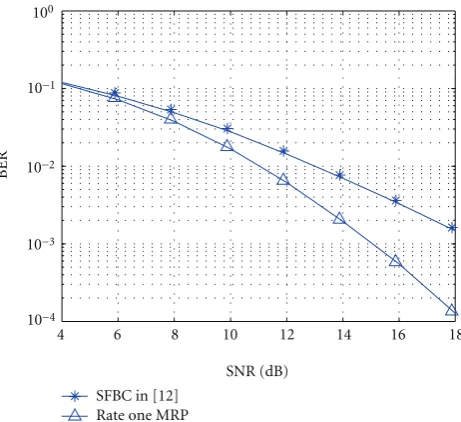
6. Simulation Results
To illustrate the performance of the rate one MRP and the multirate MRP, we performed some simulations and made comparisons with existing SFBC given in [12]. For example, if P = 3, transmitted symbols S (P ×Nt matrices) using
the rate one MRP and the SFBC in [12] are given by the following, respectively,
S=
⎡ ⎢ ⎢ ⎢ ⎣
s1 s1
s2 s2ejφ2,2
s3 s3e2jφ2,2
⎤ ⎥ ⎥ ⎥
⎦, S= ⎡ ⎢ ⎢ ⎢ ⎣
√
2s1 0
0 √2s2
√
2s3 0
⎤ ⎥ ⎥ ⎥
⎦, (46)
4 6 8 10 12 14 16 18
BER
SFBC in [12] Rate one MRP
SNR (dB) 100
10−3
10−4
10−1
10−2
Figure6: Performance of the rate one MRP and the SFBC in [12] for the MIMO-OFDM system withNt = 2,Nr = 1,Nc = 512, andδ=128 in the propagation scenario with uniform PDP of two paths.
where S = [s1,s2,s3] = CΘ. The constellation A of the
codewordC is chosen to be quaternary phase-shift keying (QPSK) or 16QAM. The precoding matrix Θ is given by (34). The optimal rotation anglesφ2,2of the rate one MRP
are given by the second column of Table 2. The channel state informationH and the rotation anglesφ2,2are perfectly
known by the receive antennas. However limited knowledge of channel PDP is available at the transmit side. The decoding process is unified at first in all simulations according to [35]. The same sphere decoding [36, 37] is used at the receive antennas for each subsystem and each SFBC. The bit error rate (BER) performance is averaged over all MIMO-OFDM subsystems and channel realizations.
6.1. Diversity Loss. The SFBC without optimization pro-cess might lose the diversity gain for specific propagation scenario. It has not been completely recognized but this problem can be overcome by adjusting subcarrier interval
δ or applying proposed MRP. We assume that the MIMO-OFDM system hasNt = 2,Nr = 1, 16 MHz Bandwidth, andNc = 512 subcarriers. Each subsystem hasP =4 well-separated subcarriers and a fixed subcarrier intervalδ=128. The propagation scenario has only two delay paths or two dominant delay paths. It is shown in (14) that for this kind of system setting and propagation scenario, the powers of paths are irrelevant to the SFBC design process. Hence it is assumed that the wireless channel has uniform delay power andσ2=1/2 for simplicity. The time delays are assumed to
τ0=0 andτ1=2Ts/Nc. The rate one MRP is compared with
the SFBC in [12] with an exactly same system configuration. The optimal rotation angleφ2,2of the rate one MRP for this