20th International Conference on Structural Mechanics in Reactor Technology (SMiRT 20) Espoo, Finland, August 9-14, 2009 SMiRT 20-Division 4, Paper 1629
Residual Stress Analysis of an Overlay Weld on a Dissimilar Metal Weld
Kang Soo Kim
a, Ho Jin Lee
a, Bong Sang Lee
a, I. C. Jung
b, J. G. Byeon
b, K. S. Park
ba
Korea Atomic Energy Research Institute, 150, Dukjin-dong, Daejeon 305-353, Korea
, e-mail:kskim5@kaeri.re.kr
b
Doosan Heavy Industries and Construction Co., 555 Gwigok Dong, Changwon 641-792, Korea
Keywords: Residual Stress, Dissimilar Metal Weld, X-ray Method, Hole Drilling Technique, FEM Model.
1
ABSTRACT
In recent years, the dissimilar metal welds, Alloy 82/182 welds, used to connect the stainless steel piping and low alloy steel or carbon steel components in a nuclear reactor piping system have experienced a cracking due to a primary water stress corrosion (PWSCC). It is well known that one reason for the cracking is the residual stress by the weld. But, it is difficult to estimate the weld residual stress exactly due to many the parameters for welding process. In this paper, a Butt model weld specimen of was manufactured and the residual stresses of the weld specimen were measured by the X-Ray method and a Hole Drilling Technique. These results were compared with the result of the Butt FEM Model to confirm the confidence of the FEM input. Also, an analysis of the 3 FEM models made by the ABAQUS Code was performed to estimate the weld residual stress on a dissimilar metal weld exactly. 3 FEM models are the Butt FEM model, the Repair FEM model and the Overlay FEM model and are made as the 2D plane–strain model. A thermal analysis and a stress analysis were performed on each model and the residual stresses for each model were calculated and compared respectively.
2
INTRODUCTION
3
METHODS AND RESULTS
3.1 Experimental measurement of the residual stress
The material and the thermal properties for each dissimilar metal are shown in Table 1. The number of pass at the dissimilar weld part is 31 and the heat input of the welding condition was presented in Table 2. Butt weld specimen is shown in Fig. 1. The plate size of the SUS 316L and the SA 508 Gr3 is 330x330x40 mm respectively. The edge of the SA508 plate became the buttering by Alloy 182 and two plates were welded by a filler. The material of the filler and the buttering was Alloy 182. The size of the groove bottom and the buttering was 3 mm and 6 mm respectively. The measurement dislocations for the residual stress are shown in Fig. 2. The X-Ray measurement equipment and the Hole Drilling measurement equipment are shown in Fig. 3 and Fig. 4 respectively.
Table 1. Material and thermal properties @ 21 oC
E (GPa)
Poisson’ s Ratio
Thermal Expansion Thermal Conductivity (W/mm oC)
Specific Heat (J/Kg oC)
SA 508 192 0.29 1.15E-5 5.19E-2 460.24
SUS 316L 195 0.27 1.53E-5 1.29E-2 451.45
Alloy 182 214 0.27 1.22E-5 9.72E-3 397.48
Table 2. Heat input of the welding condition
Weld method Current (A)
Voltage (V)
Weld speed (cm/min)
Pass 1-2 GTAW 120-130 10-12 9-10
Pass 3-11 SMAW 120-130 21-24 13-15 Pass 12-31 SMAW 135-140 23-26 15-16
Figure 3. X-Ray measurement equipment Figure 4. Hole Drilling measurement equipment
Figure 5. Results of the experimental measurement
The results of the experimental measurement are shown in Fig. 5. Where, S11( x) is the transverse stress in the welding direction and S33( z) is the stress in the welding direction. As shown in Fig. 5, X-Ray measurement values and Hole Drilling measurement values show a trend which is in agreement at the weld part and SA 508 plate. But, the S11 values of X-Ray and Hole Drilling measurement values at the SUS 316L plate show a big deviation.
3.2 Butt FEM Model
Butt FEM Model is shown in Fig. 6 and consists of the SUS316 plate (330x330x40 mm) and the SA508 plate (330x330x40 mm). This model is made by the ABAQUS/CAE Code and the 2D plane–strain model. A thermal analysis and a stress analysis were performed on this model and the residual stresses were calculated. “Element birth” technique for the meshing and a lumping method for the bead simulation were used. 10 passes were used by the lumping method instead of the actual 31 passes. The fixed boundary condition was applied at the end the SUS 316 plate and a roller boundary condition at the end of the SA 508 plate.
4-node DC2D4(Diffusive Heat Transfer or Diffusion Elements) was used for the thermal analysis and the 4-node CPE4R(Plane Strain Elements) was used for the stress analysis. The total nodes and elements of this model are 7140 and 7409 respectively. 10 W/m2 oC as the convection coefficient was used for the weld convection and the phase transfer was not considered.
Figure 6. Butt FEM Model Figure 7. Temperature distribution of the 6th pass
Figure 8. S11( x) distribution of the Butt FEM Model Figure 9. S33( z) distribution of the Butt FEM
Model
Where, S11( x) is the transverse stress in the welding direction and S33( z) is the stress in the welding direction. As shown Fig. 10, The experimental values(S11) by the X-Ray method and the results of the Butt FEM Model have an especially large deviation at the SUS 316L plate, but as a whole, these experimental values have a trend which is in agreement with the Butt FEM Model.
3.3 Repair FEM Model
Repair FEM Model is shown in Fig. 11. A half of the plate thickness from the bottom part was removed and welded again by using a filler (Alloy 182).
Figure 11. Repair FEM Model
The total nodes and elements of this model are 10867 and 10648 respectively.
For the Repair FEM model, 8 passes were used by the lumping method instead of the actual 20 passes and the temperature distribution in the case of the 7th pass is shown in Fig. 12. The results of the stress analysis are shown in Fig. 13 and Fig. 14 respectively. Fig. 13 is the stress distribution of S11( x) and Fig. 14 is the stress distribution of S33( z).
Figure 12. Temperature distribution of the 7th pass
Figure 13. S11( x) distribution of the Repair FEM Model Figure 14. S33( z) distribution of the Repair
Figure 15. Result comparison of the Repair FEM Model and the Butt FEM model
The analysis results of the Repair FEM model and the Butt FEM Model are represented in Fig. 15. We know that the stresses of the Repair FEM Model are on a whole higher than that of the Butt FEM Model. Therefore, we know that the Overlay weld is needed to lower the stress level at the weld part, the SUS 316L plate and the SA 508 plate.
3.4 Overlay FEM Model
Overlay model is shown in Fig. 16. The top part of the plate was overlaid by the filler (Alloy 152).
Figure 16. Overlay FEM Model
Totally, 3 layers were overlaid. The total nodes and elements of this model are 12119 and 11835 respectively. Total weld passes consist of 3 passes for the Overlay FEM model and the temperature distribution in case of the 2nd pass is shown in Fig. 17. In case that the 2 layer was overlaid, the results of the stress analysis are shown in the Fig. 18 and Fig. 19 respectively. Fig. 18 is the stress distribution of S11( x) and Fig. 19 is the stress distribution of S33( z).
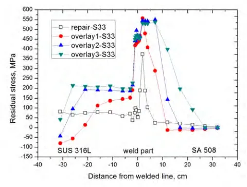
Whenever each layer was overlaid, a thermal analysis and a stress analysis were done respectively. The stress results according to the distance from the welded line on the 1st layer weld, the 2nd layer weld and the 3rd layer weld are presented in Fig. 20 and Fig. 21. Also, the results of the Repair weld are presented in Fig. 20 and Fig. 21. The stress results in the thickness direction of the weld part in case of the 1st layer weld, the 2nd layer weld and the 3rd layer weld are presented in Fig. 22 and Fig. 23. Also, the results of the Repair FEM Model and the Butt FEM Model are presented in Fig. 22 and Fig. 23.
means that the stresses in the welding direction(S33= z) due to the overlay weld were elevated. In case that the loads are applied in the welding direction at the plate structure including the dissimilar weld part, the structure might be weak. Therefore, more parametric studies (change of boundary condition etc.) are need. The stress results for the 1st layer weld, the 2nd layer weld and the 3rd layer weld at the weld part are presented in Table 3. As shown in Table 3, we know that the stresses of S11 and S33 are lowered by increasing the number of layers. If the 4th layer will be overlaid, the stresses of S11 and S33 will be lowered more.
Conclusively, we say that the Overlay weld lowers the stress in the welding part because the result stress is the resultant value of the S11 and S33. The S11 stress and the S33 stress in the thickness direction at the weld part are presented in Fig. 22 and Fig. 23 respectively.
As shown in Fig. 22, the S11 stress level in the thickness direction at the weld part converges to nearly 0 MPa according to an increasing number of layers and the S33 stress as shown in Fig. 23 converges to nearly 500 MPa according to an increasing number of layers. This means that the stress changes of the tension and the compression stress become constant. Therefore, we can say that the Overlay weld has good benefits with a view to a stress relaxation and a PWSCC.
Figure 17. Temperature distribution of the 2nd pass
Figure 20. Results of the Overlay FEM Model (S11)
Figure 21. Results of the Overlay FEM Model (S33)
Figure 23. FEM results of the Overlayweld (S33 through thickness)
Table 3. Stress results for each layer at the weld part
S11 (MPa) S33 (MPa)
Overlay 1 288 557
Overlay 2 142 545
Overlay 3 75 531
4. CONCLUSIONS
The experimental values by the X-Ray method and the Hole Drilling Technique for the Butt weld have a trend which is in agreement with the Butt FEM results. On a whole, the Repair weld elevated the stresses. We know that an Overlay weld for a relaxation of the stress at the welding part is needed. Overlay weld lowers the stress at the welding part. The stresses of S11 and S33 are gradually lowered by increasing the number of layers. The S11 stress in the thickness direction at the weld part converges to nearly 0 MPa according to an increasing number of layers and the S33 stress converges to nearly 500 MPa according to an increasing number of layers. This means that the stress changes of the tension and the compression stress become constant. Therefore, we can say that the Overlay weld has good benefits with a view to a stress relaxation and a PWSCC.
ACKNOWLEDGEMENTS
This work has been carried out under the nuclear R & D program supported by the Doosan Heavy Industries and Construction Co., Korea.
REFERENCES
ABAQUS, 2004. Standard User’s Manual, version 6.4. ABAQUS Inc., Pawtucket, RI, USA.
Brust et al., 1997 Brust, F. W., Zhang J. And Dong P., “Pipe and Pressure Vessel Cracking: the role of weld induced residual stress and creep damage during repair” SMIRT 14
David et al., 2005 David W. Wu, Raymond K. Yee, “Structural and Thermal Analyses of Pressure Vessel Bottom Head with Penetration Holes”, Proceedings of ASME PVP Conference 2005, PVP2005-71084, pp. 1-7.
Dong et al., 2000 Dong, P. and Brust, F. W., “Welding Residual Stresses and Effects on Fracture in Pressure Vessel and Piping Components: A Millennium and Review and Beyond” Journal of Pressure Vessel Technology.
Fricke et al., 2006 S. Fricke, E. Keim, J. Schmidt, “Numerical weld modeling – a method for calculating weld –induced residual stress“, Nuclear Engineering and design, pp 139-150.
Kim et al., 2008 K. S. Kim, H. J. Lee, B. S. Lee, I. C. Jung, J. G. Byeon and K. S. Park, “Residual Stress Analysis of an Overlay Weld on a Repair Weld”, Transactions of the Korean Nuclear Society Autumn Meeting.
King, 2003 King, C. P., “PWSCC of Alloy 600 Type Materials in Non-Steam Generator Tubing Applications-Survey Report Through Tune 2002”, EPRI