Thermal Analysis of the Molten Lead Kettle
Failure at the Galvanizing Plant and Development
of Novel Design Using CFD Techniques
Prasad Manoj
1, Prasad Sonal
2, Patel Amit
2, 3L & T – Chiyoda Limited, Vadodara, Gujarat, India1
Dept. of Mech. Engg., Fac. of Tech. & Engg., The M. S. University of Baroda, Vadodara, Gujarat, India2,3
Corresponding Author3
ABSTRACT: The present work discusses problem of failure of kettle holding molten lead in a galvanizing plant. A CFD code Fluent was used to solve the problem using computational approach. The geometry is built in the GAMBIT environment and 3D solvers for turbulence, combustion and radiation heat transfer was applied. The study revealed the detection of the hot spot exactly at the same location of the kettle that was observed at the plant. This confirms the validity of the CFD Model. Based on this model the suggestions are made to overcome kettle bulging. For this two approaches are suggested. They are, differential heating of the kettle and the reduction in the width of the burner. The effect of both these alternatives is studied using a CFD model and the effectiveness of the results are discussed and compared using dimensionless surface parameter representing the temperature distribution and flue gas temperature.
Based on the results obtained an improvised geometry for the kettle heating is proposed. The proposed novel design has the following features:
50% reduction in the fuel consumption and lower start-up time.
Separation of the zone of mechanical and thermal stresses and lower concentration of thermal stresses.
Increase in the heat transfer area and a reduction in the heat losses through the exhaust.
Reduction in the amount of lead used for the operation.
KEYWORDS: Galvanizing process, kettle failure, CFD code, pattern factor, kettle bulging.
I. INTRODUCTION
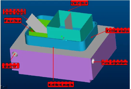
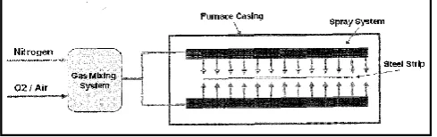
Galvanizing of steel is an energy intensive process and is carried out by passing of hot steel sheet in the pool of molten zinc. The sheet is cleaned prior to the galvanizing by allowing it to dip into the mixture of water and a cleaning agent (flux, which is ammonium chloride). Lead is used as a preheating agent and the sheet to be galvanized passes from the pool of molten lead before finally enter the molten pool of zinc. Molten pool of lead and zinc (in that order) is kept in the kettle. Fig. 1 shows the schematic of a galvanizing process. Due to the difference in the density, both the molten metal retain in the kettle as an immiscible. Molten zinc being light floats over the molten lead. A floating container, without having base is used to hold the molten zinc, so that the sheet may enter a pool of molten zinc from the bottom, after passing through (or after getting preheated) the pool of molten lead.
The thermal energy input required for sustaining molten lead and zinc is transferred from the combustion products that travel in the furnace region. Four burners located as shown in Fig.1, allows the flame to propagate in the corridor of the furnace and the combustion products surrounding the kettle. The duct for the flue gas exhaust is at the bottom of the kettle base, which is followed by the chimney.
Fig. 1 Schematic of Galvanizing process
Production of the galvanized sheet is carried out on the continuous basis. Cold rolled MS sheet, wound over cylindrical mandrill with the axis of rotation horizontal with the feed rate of 32 m/min is the input for the galvanizing process. Fuel for the burners is Furnace oil (FO) or Light Diesel Oil (LDO). Presently the total fuel consumption for all four burners is of the order of 100 liters/hr. Since lead is preheating agent for the sheet, consumption of lead is negligible. However, zinc consumption for the production rate of the sheet mentioned above is 500 kg/hr. Mass of the lead and zinc available at any time for the galvanizing are 140 and 20-21 MT respectively. Inside dimensions of the kettle are 3700(l) x 2400(w) x 1800(h), and thickness of the kettle plate is 50 mm. 351 mm of the kettle wall height is projected to the ambient air.
II. REVIEWOFLITERATURE
Present section discusses the common issues that influence the galvanizing process and the current trend prevailing in the industry.
Hot dip galvanising is the most popular method of corrosion protection. Under this the steel articles are immersed in
molten zinc at 860 F (460⁰C) to form frozen metal on the surface. Drawbacks of this technique include the expense of
heating parts at high temperature and generation of by-products such as zinc alloys, zinc oxides and smoke. Under recent policy the reduced acceptable lead levels in coating is recommended, since lead from galvanized coated steel may dissolve in the water. Such dissolved lead if consumed by human, may accumulate in human bodies with deleterious results. Another issue is the effect of molten salt layer on top of zinc (top flux) that causes kettle smoke and ash evolution, which are harmful to the human.
As an alternate to this lead free batch technology is recommended. The process used by „ThermoPrep‟ is of such type. The process protects the steel surfaces with a thermally stable flux by preheating parts to 400 to 450 F (204–
232⁰C) in separate furnace and then immersing them in molten lead free zinc for a short period of time. The use of
thermally stable pre-flux would eliminate the need for top-flux which will reduce associated wastes. The proposed method has advantages like, 20-30% productivity increase with significant reduction in energy, top ash and smoke reduction, 15% coating thickness reduction to meet specification requirement, elimination of top-flux use on the kettle, ability to produce defect-free and lead-free zinc coating and increased kettle life [3].10-
Fig. 2 Schematic of ThermoPrep process
The issue of oxidation of alloying element is a major concern while carrying out the galvanizing. New steel grades (refereed as advanced high strength steels) with a very high yield point having a high elongation capacity have been developed over the years to meet the demands of higher safety and lower weight in the car industry. These steel raise some problems because some of the alloying elements such as manganese, silicon, aluminum, chromium may result in a thin layer of oxides on the steel surface during the annealing operation preceding the dipping in the galvanizing bath. This oxidation harms the zinc wettability and thus the quality of coating. The solution which is proposed is to subject the strip surface to temperature and atmosphere conditions fit for quickly and deeply oxidizing the alloy components in the direct fired furnace which is part of annealing furnace, thereby avoiding migration of oxidisable elements towards the surface followed by reducing the iron oxide back to iron in the radiant tube section. Then steel strip is dip in Hot dip galvanizing line where the oxygen content is 0.5 to 10%. The oxygen values above 10% the oxide layer did not have the desired composition and the growth rate of the oxide layer is too high resulting in thick oxide layers. At oxygen values below 0.5% the oxidation process was too slow and the oxide layer remained too thin. In a preferable embodiment the gas mixture comprises an oxygen content of between 2 to 4.5%. In an embodiment the oxidation of the
steel strip surface or surfaces takes place between 650 ⁰C and 900 ⁰C.
steels (AHSS). During annealing in the continuous annealing furnaces of hot-dip galvanizing lines, the alloying elements of AHSS form selective oxides. This can lead to undesirable quality defects during the coating process. The dewpoint control and the oxidation/reduction technique are key technologies for the hot-dip process of AHSS [16].
A dual-purpose production plant for cold rolled steel sheets and hot-dip galvanized steel sheets comprising, successively disposed in series is also found to have taken place. Such plants consist of a heating zone, a soaking zone, a primary cooling zone, an over-aging zone equipped with a controlled cooling facility, a molten galvanizing zone, an intermediate cooling means, a secondary cooling zone, a temper rolling means, and a chemical treatment means, and a bypass means for directly connecting over-aging zone and secondary cooling zone with each other. Another object is to provide a plant for producing deep drawing hot-dip galvanized steel sheets, particularly for car bodies, having zinc plating with good adhesive strength and having excellent performance characteristics as well as for producing galvanized steel sheets of high strength steel which is hardened by solid solution and dual-phase structure [18].
The flux-galvanizing process serves as a viable process for the continuous galvanizing of steel sheet. Although it has its own unique processing problems, such as the formation of flux fumes and flux ashes that need to be handled as waste products, it is a method of galvanizing that allows the construction of a galvanizing line without the expense of the typical large annealing furnace associated with the hydrogen cleaning method. For many producers of galvanized sheet, the annealing of steel sheet is an integral part of the complete steel processing procedure, and they incorporate the annealing furnace into the galvanizing line so that the hydrogen cleaning concept can be used. But, for those smaller manufacturers who want to purchase steel sheet and apply a zinc coating for corrosion protection, a flux galvanizing line is an alternative process – one that requires less capital expenditure [11].
Furnace burners are key component in galvanising. There are basically three types of furnaces or burners used in practice, flat flame burner, force circulation burners, high velocity burners. The plants mostly are found to have end firing type, the major advantage under this are, uniform kettle wear, better fuel efficiency and low maintenance, especially in case of the failure of the burner. With correctly designed furnace if the burner tube fails, the flame is directed along the gallery and not into kettle. Failure of flat flame burner and side wall mounted high velocity burners with a cranked firing tube can burn out the kettle in less than 48 hours, if the firing tubes fail or the flame pitched forward. The high velocity gas or oil-fueled burners are mounted into one or two diagonally opposite corners of a continuous gallery running 360 around kettle. The output momentum of the burners firing at upto 500 ft/sec causes a rapid recirculation of hot gases around the kettle producing high rates of heat transfer for all available points on the kettle. The bulk flow of the recirculating gases absorbs the intense local burner heat redistributing it evenly around the periphery of the kettle. This result in high operating efficiency and uniform heat transfer both around the kettle and over its depth leading to low uniform kettle wear [10].
When a gaseous fuel is mixed with air within its limits of flammability the mixture can be burned to release heat. Only 90% of the heat is usefully available. The rest 10 % of the heat can be attributed to either heat lost in production of steam in the products of combustion, heat loss through the furnace insulation, heat lost in heating kettle or Heat lost with flue gases from the furnace [10].
It is essential to account for the system efficiency for the galvanising plant. The system efficiency is defined as the gross heat input which is transferred from the combustion products as they pass through the furnace. The system efficiency can be derived as a function of the volume of the excess air used in combustion and of the temperature of the flue gases upon the exiting the furnace. Complete combustion of the fuel cannot be achieved with less than 0% excess
air. Another limitation is if the zinc temperature is 840 F (450⁰C) than the flue gas temperature should be more than
840 F (450⁰C). From this parameters maximum theoretical system efficiency for a furnace operating on natural gas is
Wear of kettle is most crucial issue while deciding the operational issues of the galvanizing plant. In heating galvanizing baths, temperature uniformity is of prime importance, as these evens out the wear rates at different parts of the kettle and gives longer life. Temperature Uniformity is best achieved by the convective heat transfer, which results from circulating hot gases around the bath at a high speed. As the gas speed increases so the temperature of the gas required for heat transfer falls. Lower as temperatures give less storage of residual heat, better control and lower case losses as well as enabling more cost-effective use of materials. Firing at high output also gives more efficient mixing in the burner and eradicates the production of poisonous carbon monoxide, which is caused by incomplete combustion. It also means that the burner can be accurately set at one firing rate to use the minimum amount of excess air. It is therefore advantageous to fire the burners at the highest output that can be achieved without giving rise to local high heat transfer effects in the immediate vicinity of the burners. This is the area where very careful furnace design is required [10]. Kettle wear is a function not only of the temperature to which the kettle is over-heated but the time for which that over-heating occurs. In order to understand galvanizing furnaces and select a furnace for a galvanizing plant, some of the basic heat transfer principles involved in kettle heating must be understood. Heat produced in the galvanizing furnace must be efficiently transferred to the molten zinc bath. Inefficient heating can lead to uneven heating of the kettle walls and large temperature gradients to which the steel kettle is exposed. When steel is exposed to variations in temperature, or gradients, it degrades faster than if maintained at a constant temperature. This is constantly occurring in the galvanizing kettle because portions of the kettle wall remain hotter than other sections due to the constant temperature changes in the zinc bath. In order to extend the life of the galvanizing kettle, heat must be applied as evenly as possible to the kettle walls, as well as to maintain the zinc bath as close to a constant temperature as possible.
Another way large temperature gradients can occur is when heat is not supplied to the kettle fast enough when heavy work is put through the bath. The burners must be able to supply heat to the kettle as soon as it is lost, as the result of cooler steel being dipped into the molten zinc. The temperature drop of the kettle is also dependent on the amount of zinc in the kettle. The temperature of large kettles will not drop as much as smaller kettles when the same piece of steel is dipped in each. Potential problems may arise when the galvanizing kettle is not heated uniformly. Uneven heating of the galvanizing kettle allows for degradation of the kettle walls as a direct result of hot spots formed adjacent to areas where larger amounts of heat are directed. The kettle wall requires monitoring to ensure that “hot spots” have not developed because they grow very quickly and may result in kettle failure. Once formed, these hot spots grow at an exponential rate. When kettle wall thickness is lost, heat transfers through the thinner portions at a faster rate than other sections of the wall of greater thickness. This is because these hot spots cause the thickness of the galvanizing kettle wall to decrease in only these areas. The heat has a lower thermal resistance to overcome once a hot spot is formed as a result of the thinning wall. The heat losses are decreased when hot spots develop allowing more heat to be transferred through the kettle wall, which ultimately could result in a hole. Kettle walls must be probed regularly to ensure that hot spots have not begun to develop. If kettle wall thickness is thought to be lost in areas where the flame is directed, those areas should be repaired immediately because holes in the kettle wall will develop soon thereafter. [12]
The most common fuel used to heat galvanizing kettles is natural gas. LPG is sometimes used depending on availability and price. In the past, diesel oil fired systems were used to heat conventional galvanizing kettles. Often the choice of heat source is made due to availability; whatever heat source is the cheapest and most readily available is usually chosen to heat the kettle. Electricity can also be used to heat steel galvanizing kettles. Via electrical induction, kettles are heated by coils placed in locations similar to those of gasfired kettles. Electrical heat is the perfect heating means for a galvanizing furnace because the radiant heat produced by resistance elements is very uniform, but the high cost of electricity usually precludes the use of electrical heating [12].
III.PROBLEMSTATEMENT
After a few weeks of operation bulging of the kettle is found to occur at the base of the kettle wall both at the longer as well as shorter side. This may leads to the development of cracks and lead to total failure of kettle.
Significant bulging at longer side is observed as compared to shorter side. It appears „prima facie’, that bulging is due
IV.MODELINGTHEGALVANIZINGFURNACE
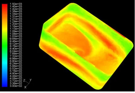
The system is modeled, meshed and exported in Fluent CFD solver. The various components of the galvanizing furnace are, Furnace or combustion zone, Burner, Exhaust duct, Kettle with floating containers of zinc and flux, and sheet to be galvanized, in the form of stationary load. The outside wall of the furnace in contact with ambient air is considered as insulated. All other walls of the kettle, at sides and bottom are considered to be conductive. Species transport model is used for combustion. The temperature distribution at the outer surface of the kettle for the given geometry and the corresponding boundary conditions, solved in Fluent 6.1 and the temperature distribution over the surface of the kettle is as shown in Fig. 3. It can be observed that the kettle surface temperature is higher at the bottom of the vertical walls of the kettle. Further, it can be stated that presence of such temperature concentration zone are significant at the bottom wall-2, as compared to wall-1.
Fig. 3 Temperature over the surface of kettle
It is interesting to note that at these very places, the actual furnace wall showed the presence of mechanical stress. Mechanical stress increases continuously, traversing from top to bottom for all walls. Further possibility of buckling increases with increase in the unsupported length (traversing away from corners). Wall-2 is highly susceptible to failure under buckling stress compared to wall-1. It can be observed for the kettle wall, if considered as beam, that buckling stress will be prominent in the direction parallel to the base (in this case, the beam is subjected to the condition of „both end fixed‟). In contrast to this, buckling stress in the direction perpendicular to the base will be less prominent (in this case the beam is subjected to the condition of „one end fixed and one as free‟). Hence zone of high mechanical stress is at bottom of the wall-2. Fig. 3 suggests that the zone of high thermal stress is, same as earlier, at the bottom of wall-2. The kettle bulging is a metal failure, caused due to the thermally induced mechanical stresses at the bottom of the longer sides of the kettle. At the base of the kettle, one can observe that mechanical stresses are due to the hydrostatic load of molten lead, where thermal stresses are also present. However, the presence of several small square projections over which the kettle is resting, actually reduces free length and makes structure stronger against the possible failure from bottom. For the purpose of thermal stress analysis and to compare various alternatives for the solution of thermal stress included bulging, a single, unified and dimensionless number called „Pattern Factor‟ (PF) is proposed. PF is defined as a ratio of the difference of temperature (i.e. maximum and average) over the average temperature of the zone under consideration.
max avg
avg
T
- T
PF =
T
… … (1)
When average temperature prevails over the entire region under consideration, the thermal stress will virtually vanish. In other words, any alternative, which results in to lower value of PF, must be preferred.
Consideration of the temperature ratio in the definition of pattern factor may be attributed to the following:
1. It is the non-uniform temperature distribution that is responsible for the generation of the buckling stress that leads to bulging.
The flue gas temperature can also be another important parameter for determining the effectiveness of the heat transfer. Since not only the uniform deployment of the heat to the walls of kettle is important, but also the maximum heat transfer to the wall is accounted in overall cost determination. Therefore uniformly distributed heat flux at a possible maximum rate ensures an effective thermal performance and efficient galvanizing process.
V. PROPOSEDALTERNATIVES
Two possible alternatives are proposed to tackle the problem of bulging of kettle:
1. Different fuel consumption rate at the burner of the furnace (for burner 1 & 3), and
2. Adopting smaller width, W between the furnace wall and kettle surface.
1. Introduction of different fuel Consumption Rate
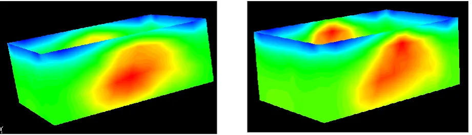
Referring Fig. 3 it can be observed that reasons for concentrated thermal stress at the bottom of the kettle walls (wall 1 & 2) are higher heat released by the hot flue gases. Flow pattern of the flue gases suggest that the heat released by burner 1 & 3 at wall-1, reaches at the bottom of wall-2, leads to higher PF. Hence fuel reduction at the burner-1 is tried. Under this option, two reduced fuel consumptions (one with 25% & with 50% of the rated value), are studied.
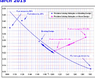
From Figs. 4 & 5, it can be seen that in the case of 25% fuel reduction, concentration of thermal stress is shifted to little upward at wall-2. In case of 50% reduction, the concentration of thermal stress is shifted significantly upward. Both attempt decouples the thermal and mechanical stresses, and reduced the chances of bulging.
VI.RESULTSANDDISCUSSION
Table 1 and Fig. 7 summarize the results of the alternatives attempted with respect of PF and TF. It is observed that
with the decrease in the fuel consumption, PF scenario worsens (TF reduces for obvious reasons). On the other hand
option of reduction in the width gives lower (better) PF, and hence uniform heat transfer pattern. Amongst all options, this option provides the uniform heat availability at the inside walls of the kettle, i.e. to molten lead (refer column 1 of
Table 1). However, for this option higher value of TF, hints poor utilization of the fuel. Although, this option may be
attractive for the management, since this allows management to meet its production demand (with lower down time), at the cost of little additional fuel consumption. For existing design it is observed that for all the alternatives, product of
PF and TF is almost constant. Hence out of the two alternatives (uniform and maximum heat transfer) all alternatives
address only one aspect at the cost of another. Referring to the Fig. 7 it appears that any alternative will essentially
follow a characteristic line, which is a hyperbolic in nature for the two given parameters, namely PF & TF.
Above characteristic suggest constrain imposed in the existing design in terms of the location of the burners. Hence in order to generate better PF, greater control over both, number and location of the burners are essential. This suggests that in order to optimize both, uniform and maximum heat transfer, entire designs must be modified and problem of bulging should be attempted with a fresh thinking (refer Fig. 7).
Fig. 6 Reduction in the furnace wall gap Fig.7 PF v/s TF for various alternatives
Tmin Tmax
PF TF
Tmax Tavg
304 918
0.2912 1165
915 445
Fuel ↓ by 50%
308 976
0.3775 1087
961 441
Fuel ↓ by 25%
308 995
0.4239 1119
1000 435
Width ↓ by 50%
321 930
0.1175 1302
927 521
Novel design
Tmax PF T
F
Tavg
Fuel consumption 50 lit/hr
798.00 0.31
90 1289
531.00
Fuel consumption 55 lit/hr
862.00 0.23
14 1206
534.00
Table1.PF & TF for existing design Table 2.PF & TF for Novel design
VII. NOVELDESIGNOFGALVANIZINGPROCESS
Figs. 8 & 9 illustrate the schematic of a conceptual galvanizing process. Movement of the sheet in the novel design is kept similar to that in the existing design, also the order in which sheet encounters molten lead and zinc is kept similar. For the simplicity cross section of sheet to be galvanized, kettle and furnace all are considered of circular cross sections. This also gives obvious benefit in the meshing.
To obtain better temperature distribution and control two sets of burners (with four burners in each sets offset by 45º) are provided in the design. Set-1 is exclusively for the preheating of the sheet in the lead, whereas set-2 is used to provide heat source for the molten zinc and better control over the galvanizing process.
Fig. 8 Schematic of novel design
Fig. 9 Schematic of novel design
Design also provides an opportunity to reduce the heat loss to environment from the exposed molten metal. In this case exposure of molten lead to the environment is eliminated, while the same for the molten zinc is kept constant at
615 Wm-2. Separate heat transfer sections for lead and zinc heating enable one to apply PF only to the zinc container.
To analyze the effectiveness of this design two options are tried one with the total fuel consumption as 50 lit/hr and second with 55 lit/hr.
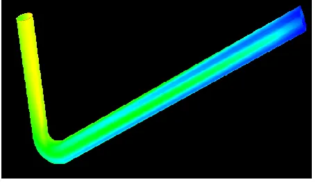
Fig. 10Temperature distribution at the Kettle
Fig. 10 shows the temperature distribution at kettle wall containing the zinc corresponding to the fuel consumption of 50 lit/hr. insignificant uneven temperature distribution can be observed in the zone. Since the number of burners proposed is eight the design is in a better position to eliminate the uneven temperature distribution. It can also result in
the lower values of PF and TF. When the values of PF and TF for both the options are compared with the values
obtained from earlier alternatives (refer Fig.7), it is observed that increasing the fuel consumption from 50 to 55 lit/hr,
both PF and TF reduces. In this way, it is possible to achieve the objective of uniform and maximum heat transfer
simultaneously.
REFERENCES
[1] A.F.Brancelli,C.Mongiello,C.Noviello,F.R.Picchia “Parametrical Analysis of a Biogas Fuel Combustion Process in a Chamber in St eady-State Condition” ,European Combustion Meeting ECM 2005,
[2] Saeed Jahangirian,Abraham Engeda,Indrek S. Wichman “Thermal and Chemical Structure of Biogas Counter flow Diffusion Flames” Energy and Fuels 2009 ,Vol.23,pp.5312-5321,2009
[3] Steel Project Fact Sheet “Energy-Efficient Process For Hot-Dip Batch Galvanizing”
[5] Naoharu Yoshitani, Member, IEEE, Akihiko Hasegawa,,”Model-based Control of Strip Temperature for the Heating Furnace in Continuous Annealing”,IEEE Transactions On Control Systems Technology,Vol.6.,No.2,pp.146-156,March 1998
[6] S G Blakey, S B M Beck, “Energy Consumption and capacity utilization of galvanizing furnaces”, Proceedings of the Institution Mechechanical Engineers, Part E : Journal of Process Mechanical Engineering , ISSN 2041-3009,Vol. 218 ,pp.251-259
[7] Brochure Sang Chareon Hot Dip Galvanize Company Limited, “Hot Dip galvanized Coating Procedure”, Certified ISO 9001:2008 [8] Bureau of Energy Efficiency, “Detailed project Report on Temperature Control in Zinc Bath in Galvanizing”, Galvanizing and Wire
Drawing SME Cluster, Report No. HWR/WDG/TCG/14
[9] European Patent Inventor : Davies,Iwan Oswyn 1970 CA Ijmuiden (NL),”Method of galvanizing a steel strip in a continuous hot dip galvanizing line”, Application number: 10193219.2 ,Date of publication 30.05.2012, Bulletin 2012/22
[10] C.S.Mason, Western Technologies,Inc. “Extending the Operating Life Of the Galvanizing Kettle”, [11] GalvInfoNote 2.7,”Galvanizing –The Use of Chemical Fluxes”, Rev 0,Jan-07
[12] John Krzywicki, Thomas langill, Ph.d., “Heat Sources & Furnaces”, Galvanizing Note, Process and Design Notes On Hot Dip Galvanizing”, American Galvanizers Association,Vol 6,No.1,June 2003
[13] Thomas H.Cook, Consultant ,Hot Springs, S.D., “Hot-Dip Galvanizing Technology”,pp19-28,August 2000
[14] Varun Singhadia, “To Study and analysis Energy Efficiency in A Galvanizing with CO2 Capturing Plant in Kailash Const. At Ricchai
Jabalpur (M.P) India”, International Journal of Emerging Technology and Advanced Engineering, ISSN 2250-2459,ISO 9001:2008 Certified Journal, Vol. 3,Issue 12,pp 354-358,December 2013
[15] “Secretary of State‟s Guidance for Hot Dip Galvanizing Processes”, Process Guidance Note 2/2,Issue 1.0,Published October 2004
[16] Martin Norden, Marc Blumenau, Rudolf Schonenberg,“ Recent Trends in Hot-Dip Galvanizing of Advanced High-Strength Steel at ThyssenKrupp Steel Europe”,pp 67,February 2013
[17] Akhil P. Deote, Dr. M.M.Gupta, Prof. D.R.Zanwar, “Process Parameter Optimization for zinc Coating Weight Control in Continuous Galvanizing Line”, International Journal of Scientific & Engineering Research, ISSN 2229-5518,Vol. 3,Issue 11,November-2012
[18] U.S.Patent, Inventor: Hideo Yokoyama, Ikuhashishi, Ichiro Shimbashi,Koichi Sakurai,both of Kitakyusyushi, Munetsugu Matsuo, Kawasakishi, all of Japan, “Dual-Purpose Plant For producing Cold Rolled Steel Sheet and Hot-Dip Galvanized Steel Sheet”, Application No. 295316, Filed Aug.24,1981
[19] U.S.Patent,Inventor: PaulFontaine,Ermlandstr. 45,D-4018 Langenfeld,Klaus Frommann, Meerbusch,Rolf Michel,Drensteinfurt, all of Fed. Rep. of Germany, “ Single or two-sided galvanizing Plant”, Application No. 177545,PCT No.PCT/EP87/00410
[20] Sarlin, Zinc Furnace “Furnace for hot dip galvanizing built around a steel kettle”
[21] N. Stockwell, C. Zhang,T. Ishii and Y. hino “Numerical Simulations of Turbulent Non-premixed Combustion in a Regenerative Furnace”, ISIJ International, Vol. 41 (2001), No. 10, pp. 1272–1281.
[22] S. Yun, M.F. Lightstone, M. J. Thomson,“An evaluation of beta PDF integration using the density-weighted PDF and the un-weighted PDF”, International Journal of Thermal Sciences,Vol.44, Issue 5, pp.421–428, May 2005
[23] A. Saario, A. Rebol, P.J. Coelho, M. Costa, A. Oksanen “Heavy fuel oil combustion in a cylindrical laboratory furnace: measurements and modeling “,ECCOMAS 2004,24-28 July 2004
[24] Mustafa Ilbas “The effect of thermal radiation and radiation models on hydrogen–hydrocarbon combustion modeling”, International Journal of Hydrogen Energy,Vol. 30,pp.1113 – 1126,August 2005
[25] F. Catoire, J.E.D. Gauthier, M.F. Bardon and A. Benaissa ”Quasi-steady state evaporation model for real multi-component fuel droplets”, Journal of the Institute of Energy ISSN 0144-2600,Vol.72,pp.134-142,1999.
[26] D. A. Jones and D.B. Clarke “Simulation of a Wing-Body Junction Experiment using the Fluent Code” Published by DSTO Platforms Sciences Laboratory, June 2005
[27] Walter L. Weaver,” Calculation Envelope: RELAP5-3D & Fluent CFD Using Segregated Solvers” Idaho National Engineering and Environmental Laboratory, August 25, 2004.
[28] Sarah M. Stitzel ,”Flow field computations of combustor-turbine interactions in a gas turbine engine” Virginia Polytechnic Institute and State University February 7, 2001
[29] H-J Tomczak, G Benelli, L Carrai and D Cecchini “Investigation of a gas turbine combustion system fired with mixtures of natural gas and hydrogen”, IFRF Combustion Journal-2002, ISSN 1562-479X ,Article Number 200207, December 2002
[30] L.S.Caretto, A.D.Gosman, S.V.Patankar, and D.B.Spalding,"Two Calculation Procedures for Steady, Three –Dimensional Flows with Recirculation”, Proceedings of the third International conference on Numerical Methods in Fluid Mechanics, Lecture notes Physics, Springer-Verlag, Vol. 19, pp. 60-68.