18th International Conference on Structural Mechanics in Reactor Technology (SMiRT 18) Beijing, China, August 7-12, 2005 SMiRT18- K09-4
THE DEVELOPMENT OF CRFD PROGRAM FOR CONTROL ROD
ASSEMBLY DROP TIME ANALYSIS
Lei Sun *
Yongtao Wei
Nuclear Power Institute of China Sichuan University, P.R.China
P.O.Box 622-207,
Chengdu, P.R.China 610065
Phone number: +86-028-85908234
E-mail: [email protected]
Jianhua
Yu
Fangyu Gu
Sichuan University, P.R.China Nuclear Power Institute of China
P.O.Box 622-207,
Chengdu, P.R.China 610065
ABSTRACT: Control rod drop time is one of the most important parameters for the safety of Nuclear Power Plant. With a deep study on this issue, a FEM program CRFD of reactor control rod drop time and history analysis is developed. The theory and program structure of CRFD is introduced in this paper. And three examples are listed for verification.
Keywords: Control Rod Assembly, Control rod drop time, Object-oriented finite element method
1 Description of CRFD Code
CRFD(control rod falling down) program is developed with C++ language, and running on C++ Builder system. The whole program consisted of about 4150 sentences.
The main characteristics of CRFD are listed as fellow:
a. CRFD program is a two-dimension FEM program. The base element is 2-D Beam; b. Input load type: Node Displacement and Node Force;
c. Time history loads are input with multi-points;
2 MECHANICS MODEL
2.1 Control Equation
Supposing the control rod assembly, guide bush and guide tube are elasticity bodies, the coupling vibration
equation is set up:
) , ( ) , ( ) ( ) ( 2 3 2 2 2 2 2 2 t x R t x P t x u I c x u I E x t u c t u m
Ai a i i i si i i i
i ∂ ∂ = +
∂ + ∂ ∂ ∂ ∂ + ∂ ∂ + ∂ ∂ +
ρ Eq.1
i
i
A
ρ
: Mass/unit length;E
iI
i:Stiffness;i
c
: Viscosity damping coefficient;si
c
: Damping coefficient of strain rate;
P
i(
x
,
t
)
: Seismic Load ;m
a:Addition mass of fluid;
R
i(
x
,
t
)
: Impact force at the time t;u: Cross displacement of component;
x:Local coordinate along the axis of control rod.
The kinematics equation of control rod assembly in upright direction is:
)
(
)
)
,
(
(
0 2 2t
F
dx
t
x
R
mg
t
z
m
n L i−
⋅
−
=
∂
∂
∑ ∫
μ
Eq.2m: The mass of control rod assembly;
z
:Upright displacement of control rod falling;)
)
,
(
(
0
R
x
t
dx
n L
i
∑ ∫
⋅
μ
:Total friction resistance;
μ
:Friction coefficient;F
(
t
)
:Fluid resistance;L:Length of control rod; n:Number of control rods.
2.2 Impact Model
The contact and impact between control rod and guide tube is a harmonious non-completely elasticity impact. In the program, the constructed force function basing on energy conservation law、momentum conservation law
and impulse law is used to define
R
(
t
)
.4 2 2 0 ) 2 1 ( ) 2 1 ( 1 )
(t a a t Ct a t Ct
F s t F t t F t F
K
m
m
m
m
E
v
v
m
m
x
v
v
m
m
m
m
C
e
x
K
C
a
v
v
m
m
m
m
C
e
x
K
C
a
x
K
a
)
(
)
(
2
)
(
)
(
)
1
(
120
80
)
(
)
1
(
30
24
2 1 2 1 2 1 2 2 1 0 1 2 2 1 2 1 5 0 4 2 1 2 2 1 2 1 3 0 2 1 0 0+
+
−
−
=
−
+
⋅
+
−
=
−
+
⋅
+
+
−
=
⋅
=
2 2 1 2 2 1 2 1)
)(
1
(
)
(
2
m
m
e
v
v
m
m
E
s−
−
+
=
m1, m2: The mass of two bodies impacted,
C
t: Contact time of impact,0
x : The Max. transformation between two bodies impacted,KF: Contact stiffness,
s
E
: Kinetic energy consumed in impact process,e: Restore coefficient of impact.2.3 Contact
Direct restraint method applied in the program is a method to deal with contact problem. It can tail the motion track of object. When contact happened, the motion restraint (non-relative motion in normal and sliding motion in tangent) and node force (press in normal and fraction resistance in tangent) are loaded on the nodes as boundary conditions. This method has a high precision for contact description and general adaptability. It does not add other special contact element, and does not deal with complicated contact condition. It also does not increase the freedom degrees of analysis system.
2.4 Friction Resistance
Coulomb Friction model is adopted to calculate the Friction resistance. When there is no-sliding motion between contact faces of two components,
F
frcN
'
μ
≤
Eq.4aWhen there is sliding motion between contact faces of two components,
F
frc=
μ
N
Eq.4bfrc
F
: Friction force;N
: Normal pressure force on contact face;'
μ
: Max. static friction coefficient;μ
: Active-friction coefficient。2.5 Fluid Resistance
range vibration、 contact judging and impact force calculation); another one is to calculate fluid resistance. In the section of structure vibration calculation, the finite element model is built up using two-dimension Beam element. It analyzes the vibration and the motion of control rod assembly under loads (force and displacement). In the section of fluid resistance calculation, theory and experiential formula are used. It could analyze fluid resistance of column moving in rounded tube.
Getting node, element, material
and load files
Start
Reading node,element and materialdata
Formingmass and stiffnessmatrix of element
Formingmass, stiffnessand damping matrix of structure
t=t0+Δt t0=0
Reading boundary conditions
Solution cross vibration equation
) ( ) ( )
(t u t u t
u 、 、
Contact judgment Penetration
judgment Reducing Δt to analyze again
Getting impact force
Friction force Calculation falling equation
Judgment the motive component reaching the last position
Output the time
End
Calculation fluid resistance
No
Falling position and velocity at upward time
No Yes
No Yes
t
t
t
=
+
Δ
4 VERIFICATION
For check up the validity of theory and program, three examples are selected for verification as follow.
4.1 Example 1
Example 1 is theory case to analyze displacement response of water tower under shock load. Analysis parameter: weight of water tower W=96.6kN, stiffness K=2700kN/m. Using Duhamel integral, theory response value is listed in table 1 and Fig. 2 to Compare the Calculation results.
Table 1 Displacement response comparison between theory and numerical results
Unit
:
mm
T(s) 0.0 0.005 0.010 0.015 0.020 0.025 0.030 0.035 0.040 0.045 0.050
p(kN) 0.0 19.32 38.64 57.96 77.28 96.60 77.28 57.96 38.64 19.32 0.0
Theory result 0.0 0.20 1.7 5.5 11.4 17.6
Numerical result 0.0 0.28 1.9 5.8 11.8 19.1
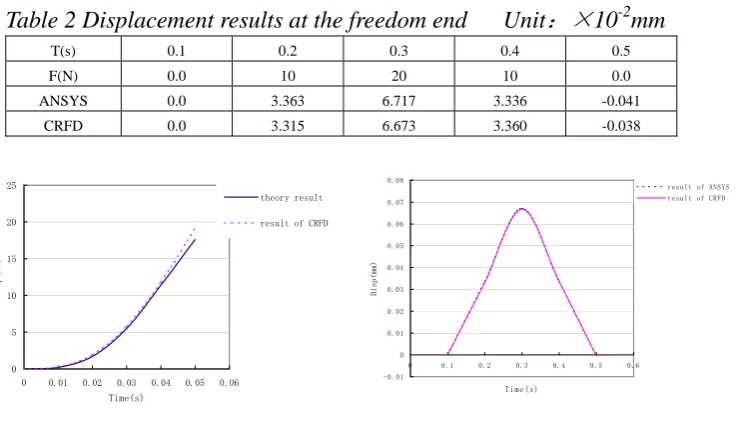
4.2 Example 2
Example 2 is a numerical analysis case. There is beam 2m length, one end is fixed, and another end loaded force F is free. Input parameter: cross section area A=2×10⁻⁴m2; area moment of inertia I=4×
10-6
m4
;elastic modulus E=2×10¹¹Pa;The results comparison are shown in table 2 and Fig. 3.
Table 2 Displacement results at the freedom end Unit
:×
10
-2mm
T(s) 0.1 0.2 0.3 0.4 0.5
F(N) 0.0 10 20 10 0.0
ANSYS 0.0 3.363 6.717 3.336 -0.041
CRFD 0.0 3.315 6.673 3.360 -0.038
Fig.2 Results of example 1 Fig. 3 Results of example 2
4.3 Example 3
Example 3 is a test case. The analysis object is a specimen of Control Rod Drive Line of Qingsan phase II, The motive components of analysis object are a hank of 24 control rods and drive rod. The guide components are guide tube in fuel assembly, lower and upper guide bush. Four different displacement seismic loads are input at the four points of drive line structure (bottom plant of fuel assembly、upper plant of fuel assembly、the cross of lower and upper guide bush and the top of upper guide bush) as same as seismic test do. The time of control rod falling from maximum hanging position to the entrance of contraction segment of guide tube (t5) and to the end of guide tube (t5+t6) are calculated. The SSE seismic is input. Analysis model is shown in Fig.4. The comparison between analysis results and test results are shown in table 3 and Fig.5. Analysis results are shown in Fig.6~9。
0 5 10 15 20 25
0 0.01 0.02 0.03 0.04 0.05 0.06 Time(s)
Disp(mm)
theory result
result of CRFD
-0.01 0 0.01 0.02 0.03 0.04 0.05 0.06 0.07 0.08
0 0.1 0.2 0.3 0.4 0.5 0.6
Time(s)
Disp(mm)
Table3 The Control rod falling time comparison between analysis results and test
results Unit
:
s
t5 t5+t6
Analysis Test Analysis Test
Falling without load 1.39 1.24 1.94 1.80
SSE 1.40 1.34 1.98 1.89
1.414 times SSE 1.43 1.41 2.11 1.98
1.6 times SSE 1.55 1.50 2.15 2.07
Fig.6 Time history of control Fig.7 Time history of control
rod displacement under rod falling velocity under
different seismic loads different seismic loads
Guide assemblyControl rod assembly
S1
S2
S3
S4
Input seismic load
Add-structure
(contact Judgment)
Fig.4 Analysis model
Fig.5 Displacement time history comparison
between test and analysis
-500 0 500 1000 1500 2000 2500 3000
0 0.5 1 1.5 2 2.5
Time(s)
Fraction force(N) 0
0.5 1 1.5 2 2.5 3 3.5 4
0 0.5 1 1.5 2 2.5
Time(s)
Veloci
ty(
m
/s)
SSE 1.414 times SSE 1.6 times SSE Time (s)
Dis
p
lacem
ent
(
mm)
Test result
Fig.8 Time history of fluid Fig.9 Time history of friction force
resistance under SSE under SSE
5 CONCLUSION
The finite element program CRFD developed by this paper can carry out the time history analysis of control rod falling from maximum hanging position to the end of guide tube, and the test parameters required are just friction coefficient, restore coefficient of impact and contact time.
CRFD program have several characteristics as fallow:
a. The constructed force function coming from energy conversation law、 momentum conversation law and impulse law is used to calculate impact force. The impact model can embody the impact characteristics better;
b. Adopting direct restrain method to deal with contact problem, solving the judgment of dynamic contact well;
c. Using the method of combination of theory and experience formula to calculate fluid resistance, putting it breaking away from test mensuration preliminary;
d. Adopting object-oriented programming method to develop CRFD, making the program better with reliability and expansibility.
Through several verifications, it is approved that the CRFD program is effective. It can be applied to take a pre-judgment of rationality of driveline system in design stage of reactor for designer.
Reference:
[1] T.J.Chung, Finite Element Analysis in Fluid Dynamic, McGraw-HillInc., 1978
[2] J. Stabel H. P. Fuchs, Influence of seismic excitation on the drop time of control assemblies in PWR’s, Transactions of the 9th International Conference on Structural Mechanics in Reactor Technology, P1121~1125 [3] Rusan. Krajcinoric, Vibration of two coaxial cylindrical shell containing fluid, Nuclear Engineering and Design, 30(1974), P242∼248
0 500 1000 1500 2000 2500 3000 3500
0 0.5 1 1.5 2 2.5 Time(s)
Fl
ui
d
re
s
is
ta
nc
e(
N)
-500 0 500 1000 1500 2000 2500 3000
0 0.5 1 1.5 2 2.5
Time(s)