The Mixed Oxide (MOX) Fuel Fabrication Facility Project
McConaghy, John M.1), Johnson, James V. 2), Bradley, Terry L. 1), Li, Chin T. 1), Meisenheimer, James K. 1), Tsai, Nien C. 1) 1) Duke Cogema Stone & Webster, Charlotte, NC
2) United States Department of Energy, Washington, DC
ABSTRACT
A team comprised of Duke Engineering & Services Inc., Cogema, and Stone & Webster Inc. will design, build, and operate a mixed oxide (MOX) nuclear fuel fabrication facility to be constructed at the US DOE’s Savannah River Site (SRS). The facility will convert surplus weapons-usable fissile material to fuel for commercial nuclear reactors. The project will be licensed by the US Nuclear Regulatory Commission (NRC). The primary, multistory, facility includes a MOX processing area, an aqueous polishing area, and a shipping and receiving area. These structures are designed and constructed to the requirements typically used for safety-related systems and structures at nuclear power plants. The paper presents an overview of the MOX fuel fabrication facility, the project description and schedule, regulatory requirements and design criteria, structure safety classifications, and seismic structures. The primary focus is on analysis and design of seismic structures, including natural phenomena hazards and soil-structure interaction.
INTRODUCTION
The Mixed Oxide (MOX) Fuel Fabrication Facility (MFFF) will be located at the US DOE’s Savannah River Site. The MFFF is designed to produce completed MOX fuel assemblies for use in domestic commercial nuclear power reactors. The feed material is depleted uranium oxide and surplus plutonium oxide from the Pits Disassembly and Conversion Facility (PDCF) supplied by the Department of Energy (DOE). The plutonium oxide is first “polished” to remove impurities. The MOX fuel fabrication process consists of blending this plutonium oxide with depleted uranium oxide, forming the mixed oxide into ceramic pellets, loading the pellets into fuel rods, and assembling the fuel rods into fuel assemblies. Once assembled, the fuel assemblies are transported to specific domestic commercial reactors for use as nuclear fuel. The MFFF is designed to process 3.5 metric tons of plutonium annually, for a total disposition of 33 metric tons of plutonium (as oxide). The MFFF will be licensed by the Nuclear Regulatory Commission. The primary structures will be designed and constructed similar to “nuclear safety related” structures for US nuclear power plants. Major schedule milestones for the project are as follows:
Complete Design - 2002 Start Construction - 2003 Begin Operations - 2006 Mission Complete - 2021
FACILITY DESCRIPTION
Site
The MFFF comprises an area of approximately 41 ac (16.6 ha). Approximately 17 ac (6.9 ha) of the site are developed with buildings, facilities, or paving. The remaining 24 ac (9.7 ha) are landscaped in either grass or gravel. No highways, railroads, or waterways traverse the MFFF site, and the movement of material and personnel to and from the MFFF site takes place via the SRS internal road system.
A double fence perimeter intrusion detection and surveillance (PIDAS) fence surrounds the Protected Area of the MFFF. The Protected Area occupies approximately 14 ac (5.7 ha) and is roughly square in shape. The MFFF Administration Building and the Gas Storage Facility are located outside the PIDAS barrier. The Secured Warehouse Building, which is located adjacent to the site access road, is an integral part of the outer PIDAS security barrier. All other buildings and facilities of the MFFF lie within the Protected Area. The site plan and major buildings are shown in Figure 1. The general site yard elevation is approximately 270 ft (82.3 m) above mean sea level (MSL), well above the elevation of any anticipated site flooding.
SMiRT 16, Washington DC, August 2001 Paper # 1254
Buildings
Primary MFFF structures include the MOX Fuel Fabrication Building (BMF), the Emergency Diesel Generator Building (BEG), Standby Generator Building (BSG), Secured Warehouse Building (BSW), Administration Building (BAD), Technical Support Building (BTS), and the Reagents Processing Building (BRP). They provide for safe, secure, and efficient performance of all MFFF functions. In particular, the site layout and facility features satisfy stringent security criteria for safeguarding the special nuclear material utilized at the MFFF. This paper focuses on the design of the BMF.
The BMF is approximately 400 ft (122 m) by 400 ft (122 m) by 70 ft (21.3 m) high and is composed of three areas. The MOX Processing Area (BMP) contains three basic floor levels and numerous, smaller, intermediate platforms to accommodate a variety of process equipment and operations. The Aqueous Polishing Area (BAP) has seven basic floor levels. The Shipping and Receiving Area (BSR) has three basic floor levels. All three areas have a common roof level. The BMP and the BSR base levels are at grade and the BAP base level is approximately 17 ft (5.2 m) below grade. Figure 2 and Figure 3 illustrate the conceptual arrangement of the BMF.
The structural framing system for the BMF consists of reinforced concrete columns, beams, concrete shear walls, floor, and roof slabs. The base mat of the entire BMF is approximately 4 ft (1.22 m) thick. Exterior walls of the MOX Fuel Fabrication Building are reinforced concrete with an additional outer reinforced concrete retaining wall. This wall, which is part of the outer security barrier, is separated from the exterior wall of the BMF. The space between the two walls is filled with an engineered fill material that provides security functions. The roof system also includes an engineered fill material topped with a reinforced concrete slab.
Foundation Conditions
A preliminary assessment of the subsurface conditions encountered at the MFFF site indicates that the site is suitable to support the proposed structures. Because of the size and weight of the BMF, it is anticipated that approximately 15 ft (4.6 m) of high quality engineered structural fill will be required to properly control settlement of the mat foundations of the BMF and BEG, and to provide adequate bearing capacity for static and seismic loading conditions. Analysis is being performed to define specific treatment and preparation requirements that will be required for the foundation systems.
Figure 1 MFFF Site Plan
1
A E54891.75 N80120.25
F AREA
BSR
BMP
BAP BTS
BRP BSW
BSG BAD
UGS
LEGEND:
BAD Administration Bl dg
BTS Technical Support Bldg BSR Shipping & Receiving BAP Aqueous Polishing BMF MOX F uel Fab. Facility
BSW Secure Warehouse BRP Reagents Bldg
BSG Standby Diesel Gen. .
BEG Emergency Diesel Gen. UGS Gas Storage Facility BMF
BEG
Figure 2 BMF Ground Floor Plan
Figure 3 Section Through BMF
AQUEOUS POLISHING AREA
DESIGN CRITERIA
The MFFF will be licensed by the Nuclear Regulatory Commission (NRC). Licensing requirements are defined in 10 CFR 70, Domestic Licensing of Special Nuclear Material. NRC expectations for the MFFF are communicated in a project-specific Standard Review Plan, NUREG-1718. Three categories of structural design requirements are defined for the MFFF. The categories and loading conditions are summarized as follows:
• Seismic Category I (SC-I) – Normal, severe, and extreme environmental loads, including the design basis earthquake and tornado, which are applied to principal structures, systems and components (SSC).
• Seismic Category II (SC-II) – Normal, severe, and extreme loading with extreme loads limited to the design basis earthquake. These loads are applied to structures whose failure could adversely impact principal SSCs (e.g. secondary seismic interaction).
• Conventional Seismic (CS) – Normal, severe, and extreme loads with extreme loads limited to conventional seismic loads as specified by the Uniform Building Code.
The BMF and the Emergency Diesel Generator Building are the primary SC-I structures. The design basis natural phenomena hazards (NPH) are defined in Table 1. The codes, standards, loads, and load combinations used for design and construction of SC-I structures are similar to those used in the design of “nuclear safety related” structures for US nuclear power plants. Concrete design for the BMF is in accordance with ACI-349, Code Requirements for Nuclear Safety-Related Concrete Structures, and structural steel design in accordance with AISC N690, Specification for the Design, Fabrication and Erection of Steel Safety-Related Structures for Nuclear Facilities.
Table 1. Summary of MFFF Site Design Criteria
Criterion Value
Severe Wind (SC-I and SC-II)
Three-second wind speed: 130 mph (209 km/hr)
Missile criteria: 2- by 4-inch (5- by 10-cm) timber plank, 15 lb (6.8 kg) at 50 mph (80.5 km/hr); max. height 50 ft (15.2 m)
Extreme Wind/Tornado (Wind Loads)
(SC-I)
Three-second wind speed: 240 mph (386 km/hr) Atmospheric pressure change: 150 psf (7182 Pa) Rate of pressure drop: 55 psf/sec (2633 Pa/sec) Tornado Missile Spectrum
(SC-I)
2- by 4-inch (5- by 10-cm) timber plank Mass: 15 lb (6.8 kg)
Horizontal Impact Speed: 150 mph (241 km/hr) Vertical Impact Speed: 100 mph (161 km/hr) Maximum Height: 200 ft (61 m)
3-inch (7.6 cm) diameter standard steel pipe Mass: 75 lb (34 kg)
Horizontal impact speed: 75 mph (121 km/hr) Vertical impact speed: 50 mph (80.5 km/hr) Maximum height: 100 ft (30.5 m)
3000-lb (1361 kg) automobile
Horizontal impact speed: 25 mph (40.2 km/hr), rolls and tumbles
Wind (CS) Basic winds: 107 mph (172 km/hr)
Floods (SC-I) Design basis flood level: 207.9 ft (63.4 m) above MSL Probable maximum flood level: 224.5 ft (68.4 m) above MSL Precipitation (SC-I) Accumulative precipitation:
Fifteen minutes: 3.9 in (9.9 cm) One hour: 7.4 inches (18.8 cm) Three hours: 14.1 inches (35.8 cm) Six hours: 16.7 inches (42.4 cm) Twenty-four hours: 22.7 inches (57.7 cm)
Snow and Ice Loads (SC-I) Snow/ice loading: 10 psf (479 Pa) Seismic (Ground Motion)
(SC-I and SC-II)
STRUCTURAL ANALYSIS AND DESIGN
The structural analysis and design of the BMF is performed using the finite element code ANSYS. This finite element model serves two purposes. First, a modal analysis is performed to obtain the frequencies and associated mass participation of the building to correlate with the frequencies of a 3-D stick model used for soil structure interaction (SSI) analysis. The second purpose is to provide design forces to support the stress analysis for the various loading combinations of dead loads, live loads, wind loads, soil pressure loads and seismic loads according to ACI Code requirements.
The ANSYS model for the BMF uses shell elements to model the walls and slabs and beam elements to model floor beams and columns. The model reflects the principal structural features of the building, consistent with the objective of determining the frequency and forces for the building. The mass of the walls, slabs, beams and columns is distributed over the plate and beam elements used to model these components. The mass of major pieces of equipment is applied as concentrated masses, lumped at the equipment center of gravity by mass element. Figure 4 illustrates the ANSYS model of the BMF
The Block Lanczos method in ANSYS is used to extract the first few fundamental modes from the finite element model of the BMF. The frequency and participating mass information from this modal analysis is used to fine-tune the 3-D stick model to be used in the SSI analysis. In the ANSYS modal analysis, the bottom of the foundation mat is fixed and 25% of live load is included in the mass calculation.
The basic loading conditions such as dead load, live load, wind load, tornado load, lateral soil pressure load and seismic load are applied to the ANSYS finite element model of the building to perform the stiffness analysis to obtain the forces and moments. In this analysis, the soil foundation is modeled by soil springs at the bottom of foundation mat. The factored loading combinations are developed using an ANSYS post processing routine. Combinations of factored loads are similar to those used for nuclear power plant structures. In the post processing, the element outputs can be grouped by the wall or slab with the same thickness and column or beam with the same size. Then, the maximum force and moment from the group can be used to design those walls, slabs, beams and columns.
SOIL-STRUCTURE INTERACTION ANALYSIS
For the design of the SC-I MOX Fuel Fabrication Building (BMF), the seismic loads are determined considering the effect of soil-structure interaction (SSI). The SSI analysis follows the guidelines described in Sections 3.7.1 and 3.7.2 of NUREG 0800 for nuclear power plants. The Duke Engineering & Services (DE&S) version of the SASSI (System for Analysis of Soil-Structure Interaction) code is used in the seismic SSI analysis to properly model the structural embedment and the foundation soil extending from the finished grade to the bedrock. The properties and configuration of the soil layers and bedrock are based on the free-field site response analysis discussed previously, which accounts for the strain dependency of the soil shear modulus and damping. To account for the variability in soil properties, three soil conditions are considered. These are the best estimate, lower bound and upper bound soil conditions.
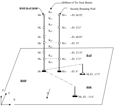
The BMF structure is modeled as two separate lumped-mass sticks, one representing the main structure and the other representing the surrounding retaining walls. The two sticks are interconnected at four different elevations where the two structures are coupled with steel beams. The roof and floor slabs are assumed rigid for the purpose of the SSI analysis. The eccentricity between the center of mass and center of rigidity at each floor is explicitly modeled in the stick representing
Figure 5 BMF 3-D Stick Model
Stiffness of Tie -back Beams
BMP,BAP,BSR Security Retaining Wall Kx1
M9 M14 --El. 66.92’
Ky1
Kx2
M8 • M13 --El. 52.5’
Ky2
M7 --El. 40.83’
Kx2
M6 M12 --El. 35’
Ky2
M5 --El. 23.33’
Kx2 BAP
M4 M11 --El. 17.5’
Ky2
M3 M10 --El. 0’
M1 El. -17.5’
BMP
BSR Z
Y N
M2--El. –11.0’
assumed rigid in the lumped-mass sticks representing the structure, the foundation mats are also assumed rigid to maintain consistency in the modeling assumption. The structural damping for the reinforced concrete BMF structure is 7% of critical.
The seismic input motion to the seismic SSI analysis is the free-field design earthquake motion specified at the finished grade. Three synthetic time histories are generated for use as the three components of the seismic input ground motion. The synthetic time histories conform to the guidelines specified in Section 3.7.1 of NUREG-0800. They are statistically independent of each other. Both their response spectra and power spectral density (PSD) function envelop the corresponding design spectra and minimum target PSD function, respectively.
The SSI analysis is repeated for each of the three soil conditions. Two types of seismic response are extracted from the SSI analyses. The first type of response consists of the maximum seismic acceleration and torsional moment at each floor elevation. These are applied as equivalent static seismic loads in the static analysis of the finite element model of the integrated MFFF structure in order to determine the seismic forces/moments in the various structural elements. The second type of response includes the floor response spectra generated at each floor elevation for use in the seismic design of supported systems, structures and components. At each of the roof or floor elevations, the floor response spectra calculated from the SSI analyses for the three soil conditions are first enveloped. The floor spectrum envelope is then broadened by
±15% to account for the effects of the uncertainty in structural properties, modeling and SSI analysis techniques. For systems, components and equipment located at or near the center of a flexible roof or floor slab panel, an additional vertical response spectrum envelope is generated at the center of the corresponding floor slab panel to account for the effect of the additional dynamic amplification due to the floor slab flexibility.
GEOTECHNICAL ENGINEERING
The MFFF is located on sediments of the Atlantic Plain in South Carolina, which are stratified layers of sand, clay, limestone and gravel. In general, the site soils are over-consolidated and quite stiff. The depth to crystalline bedrock at the MFFF is approximately 835 ft (255 m). The upper soil units at the MFFF site consist of nearly level to slightly sloping, well-drained soils. The depth to groundwater at the MFFF site is greater than 60 ft (18.3 m).
In the immediate region of the MFFF at SRS, there are no known capable faults. Several faults have been identified from subsurface mapping and seismic surveys, the largest of which is the Pen Branch Fault. There is no evidence of movement within the last 38 million years along this fault. Historically, two large earthquakes have occurred within 186 mi of SRS. The largest of these, the Charleston earthquake of 1886, had an estimated Richter scale magnitude ranging from 6.5 to 7.5. The SRS area experienced an estimated peak horizontal acceleration of 0.10g during this earthquake. This distant historical event dominates the seismic hazard at the MFFF site. Earthquakes capable of producing structural damage are not likely to occur in the vicinity of SRS.
A project-specific field exploration and laboratory test program was conducted for the MFFF. Initial results confirm that subsurface conditions encountered at the MFFF site are consistent with those reported in previous geotechnical investigations for the nearby F-Area at SRS. No unusual subsurface or conditions were encountered at the MFFF site.
During the site investigations, some isolated soft zones were identified at depths greater than 90 ft (27.4 m) on the MFFF site. These are consistent with soft zones encountered in previous investigations in the adjacent F-Area. The exploration borings and cone penetration test holes were used to define approximate limits of any substantial soft zones encountered. Critical structures, such as the BMF and the BEG, have been located so that they are not directly over any identified thicker soft zone units. Both static and dynamic analysis will be performed to evaluate the potential effect of any soft zones that may be located near or beneath any of these critical structures. If analyses demonstrate that soft zones at depth will collapse with motions associated with the Design Earthquake, potential resulting surface settlements will be evaluated. The building structures will be reinforced to withstand the calculated settlements or relocated so that they will not be adversely affected by settlement determined at foundation grade.