Division IX (include assigned division number from I to X)
STRUCTURAL STRESS ANALYSIS OF SOCKET WELDED PIPE WITH
WELD DEFECT
Seung-Jae Kim1, Hyun-Jae Lee1, Dong-Min Lee2, Yun-Jae Kim3 1
Graduate Student, Mechanical Engineering, Korea University, Korea 2
Principal Research Engineer, Technology Research & Development institute, KEPCO Plant Service & Engineering, Korea
3
Professor, Mechanical Engineering, Korea University, Korea
ABSTRACT
Small bore pipes in secondary piping system are usually socket welded and during welding process, incomplete penetration defect is formulated. To predict fatigue life of socket welded pipe with defect using FE, structural stress method is used. In this paper, structural stress analysis for defect geometries are studied. To consider crack propagation, equivalent structural stress is derived using stress intensity equation of socket welded pipe from FE analysis. Using equivalent structural stress, master S – N curve of socket welded pipe is proposed as a result of this paper.
INTRODUCTION
Secondary piping systems in power plant are consisted of various small bore pipes which are usually socket welded for connection. These socket welded pipes are under fatigue and vibration conditions, which can affect system life. Also, geometrical discontinuity region and defect due to incomplete penetration can increase stress concentration and cause crack initiation which lead to fatigue failure. In addition, each structures with various defect sizes, lengths and weld geometries could have different S-N curve and fatigue life. For that reason, to evaluate fatigue life of new defect in structure, additional fatigue tests should be performed. These cost a lot of money and time to predict structure life. For that reason, prediction methods of fatigue life of structures which include geometric discontinuity region are being developed to lower the cost of maintenance.
To evaluate fatigue life considering geometric discontinuity, Nominal stress approach method is proposed. The method uses nominal stress to calculate stress, which can evaluate structure easily. However, because area of geometric discontinuity region is so small that calculated stress proposes too conservative result. In order to lower the conservative, stress concentration factor which can consider stress concentration because of geometric discontinuity is used. This method is known as notch stress approach method. These methods can predict stress easily, however, additional tests should be performed when predict another structural life of geometry.
In order to evaluate structural life without additional tests, hot spot stress approach is proposed. FE analysis is used for calculating stresses. Extrapolation using stress values at some distances from geometric discontinuity is used to predict stress. Hot spot stress approach can predict stresses without additional experiment of another cases. But, hot spot stress is affected by stress values which are used to extrapolation, mesh size effect could be a problem.
As one of method to evaluate fatigue life of structures using FE analysis, Structural stress method is developed by P. Dong. This method can predict stress and fatigue life of discontinuity region using FE analysis without additional experiment Also, structural stress method shows mesh-insensitive result different from notch stress approach.
Defects are inserted at socket weld region and categorized by defect size along thickness and length along radial direction. Applied stresses are modified using structural stress method using FE analysis. Structural stress tendencies and stress intensity factors depend on defect size and length are proposed. As a result of this paper, master S-N curve of socket welded pipe considering fracture mechanics is proposed.
SOCKET WELED PIPE FATIGUE TEST
Socket welded pipe specimen
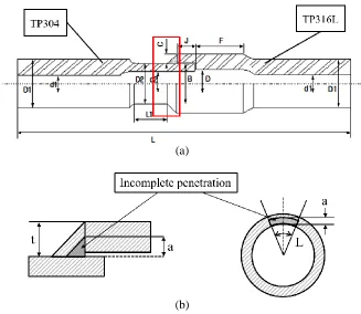
In order to evaluate fatigue life and S-N curves of socket welded pipe with incomplete penetration defect, socket welded pipe specimen for 4 - point bending fatigue is designed. As shown in Figure 1 (a), socket pipe made of TP316L and straight pipe made of TP 304 are socket welded. Thickness of socket weld is 4.9 mm and shape is isosceles right angle. Diameters and length of specimen are shown in Table 1. In socket weld region, incomplete penetration defect is inserted. The shape of weld defect is as same as socket weld shape, isosceles right angle. The defect is categorized by a/t as a ratio of defect size and thickness of weld and L as a defect length calculated by degree, as depicted in Figure 1 (b). 4 – point bending fatigue test cases are set considering size a/t and length L of defect.
(a)
(b)
Figure 1. Geometries of socket welded pipe specimen with incomplete penetration defect, (a) socket welded pipe and (b) incomplete penetration defect
Table 1: Dimensions of socket welded specimen.
D1 D2 d1 d2 t J F C B D L L1
Dimension
(mm) 30.0 26.7 16.0 18.9 3.9 12.5 24.0 4.90
Max. Min. Max. Min.
4 - bending fatigue test
4 – point bending fatigue test is performed using hydraulic tensile/fatigue tester (INSTRON - 8801, 8502) as shown in Figure 2. Bending stress is applied to both side of specimen using simply supporting grip. Applied bending stress is determined by average bending stress of outer and inner diameter of socket pipe region. Fatigue stress is applied as stress ratio R = σmin/ σmax = -1.
Figure 2. 4 – point bending fatigue tester
S – N Curve of socket welded pipe with incomplete penetration defect
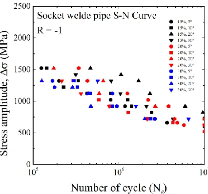
As a result of fatigue test, S – N curves of each defect cases are proposed as shown in Figure 3. Because of difficulty to insert weld defect, defect geometries are different in spite of same defect cases. From that reason, it is difficult to find defect size and length effect on fatigue life of socket welded pipe. However, Crack initiates at incomplete penetration region and mostly propagates along weld thickness direction, 90o as shown in Figure 4. 0o and 45o direction crack propagations are also observed while crack propagated along 90o direction in some cases.
Figure 4. Fatigue crack propagation observation
STRUCTURAL STRESS ANALYSIS
Definition of structural stress
Incomplete penetration defect in socket welded region may have various geometries, so it is in-efficient to test for each defect to evaluate fatigue life of socket welded pipe. To avoid additional test and evaluate stress, P. Dong proposed mesh-insensitive structural stress using FE analysis.
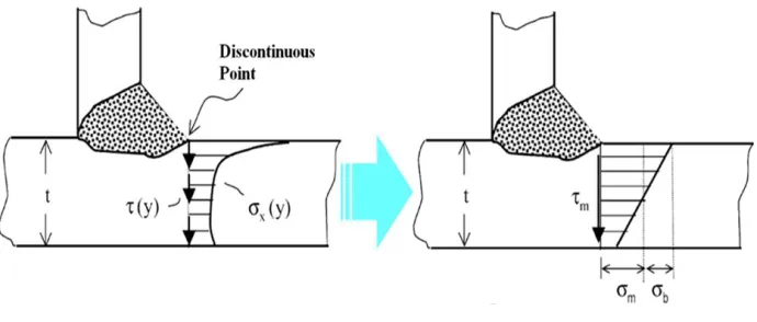
Structural stress is defined as sum of membrane and bending stress. Theses stresses are calculated using force and moment equilibrium along crack propagation direction as shown in equation 2, which enables structural stress mesh-insensitive. Calculated structural stress represents stress at discontinuous point of structure. In this paper, nodal force and moment along crack propagation direction are used to calculate membrane and bending stress.
Figure 5. Concept of structural stress approach
s m b
(1)
2 2
0 ( ) 0 ( )
2 6
t t
m b x xy
t t
y ydx y dx
0
1
t m xdx
t
(3)
2
2
0 0
6
( ) ( )
2
t t
b x xy m
t y ydx y dx
t
(4)
Structural stress analysis of socket welded pipe specimen
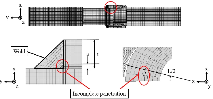
In this paper, to predict fatigue life of socket welded pipe without additional test, structural stress is used to develop master S – N curve based on proposed S – N curve. From the result of fatigue test, 0o, 45o, 90o crack propagation is determined to structural stress calculation direction. In order to evaluate structural stress along each direction, FE models which have incomplete penetration defect are designed. Figure 6 shows designed 1/2 FE model. All incomplete penetration defects are designed as an ideal geometry as same as Figure 1 (b). ABAQUS CAE is used for modelling. And 40,000 to 70,000 2nd order 3D elements are used.
Boundary conditions are determined to simulate 4 – point bending fatigue test. Figure 2 shows that 4 grips are simply support the specimen. Hence, node sets of 1/4 and 3/4 of specimen length are fixed to x direction. Also, each sides of specimen node sets are coupled to x axis to apply bending moment as same as fatigue test. Elastic FE analysis is used to calculate structural stress, and used young’s modulus of TP 304 and TP316L are 193 GPa. Poisson ratio
υ
of two materials are determined as 0.3. Commercial program ABAQUS 6.13-4 is used for FE analysis.Figure 6 FE Model of socket welded pipe specimen
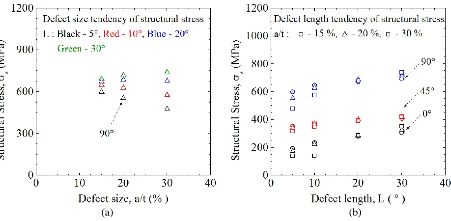
As a result of structural stress approach when fatigue load is applied, structural stress amplitude distribution along defect length is proposed in Figure 7. In Figure 7, the maximum stress amplitude is located at the centre of defect and this tendency is same for all crack propagation directions. When maximum stress amplitudes of direction are compared, structural stress along 90o direction has maximum value as shown in Figure 7.
increased, tendency is changed by crack length. If defect length is longer than 20o, structural stress increases. Different from this result, structural stress decreases when defect length is shorter than 20o. These results represent that in case of evaluate fatigue life of socket welded pipe, both incomplete penetration defect size and length should be considered. Also, results show that analysis using 90o direction would simplify fatigue life prediction and show conservative result compared to other crack propagation directions.
Figure 7. Structural stress distribution along defect length for crack propagation directions
(a) (b)
Master S –N curve of socket welded pipe
Equivalent structural stress
In case of socket welded pipe, Structural stress analysis considering crack propagation is needed because pipe is under fatigue conditions which causes failure. Equivalent structural stress is modified structural stress method which is derived from generally proposed fatigue crack propagation relationship Paris’s law.
(
)
m(
kn) (
n n)
mda
C
K
C M
K
dN
(5)
In equation 5, a and N represent crack propagation and fatigue life, m and C are material constants. stress
intensity factor ΔK is a function of structural stress of structure which has notch effect. ΔK can be expressed as generally proposed stress intensity equations ΔKn, for example, edge crack in plate or
circumferential crack in pipe, and notch effect coefficient Mkn. From equation 5, equivalent structural
stress ΔSs in equation 6 is derived from integration.
(2 )/ 2 1/ 1/
(2 )/ 2 1/ 2/
( 0)
( ) (1 )
( 0)
( ) (1 )
s
s m m m m
s
s m m m m
S R
t I r R
S R
t I r R
(6)
In equation 6, Δσs, t, r and R are structural stress, thickness of crack propagation direction, bending ratio
and stress ratio each. I(r) is a function of bending ratio which includes notch effect from weld or geometric discontinuity.
Stress intensity factor equation of socket welded pipe
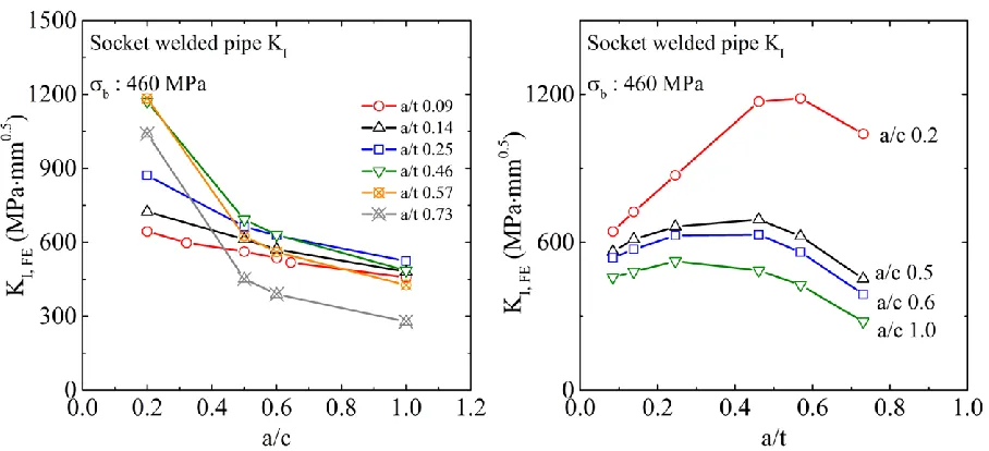
To calculate ΔK, FE model is used which considers incomplete penetration defect as a crack. Propagated crack shape is assumed as defect shape, isosceles right angle to consider all crack propagation direction. Stress intensity factor calculation point is 90o crack initiation point because maximum structural stress is located at this point. From the result of structural stress, both crack size and length are considered as variables of stress intensity factor. For FE analysis, 0.001 radius keyhole is inserted to FE model and stress intensity factor is calculated using ABAQUS 6.13-4
Figure 9 (a) and (b) show stress intensity tendencies to crack geometries. a is crack size and c is crack length which is converted from degree of crack. From Figure 9, stress intensity is increased when crack length is increased. Different from crack length effect, increasing tendency to crack size becomes to decrease when a/t is larger than 0.5. These result means that crack propagation could be delayed when crack propagates over half of thickness of propagation direction regardless of crack length.
Figure 9 Stress intensity factor tendencies to crack geometries, (a) a/c, (b) a/t
To express ΔK as an equation, Mkn and ΔKn is considered. To determine ΔKn, API 579-1 of
circumferential crack in straight pipe [5] is converted to function of structural stress and crack geometries.
From this process, stress intensity factor ΔK is expressed as an equation 7.
, ( , )
I FE s kn
a a a
K f M
Q t c
(7)
2
3.6405 5.8762
2.7224
kn
a
a
M
t
t
(8)
2 2 2
2
( , ) 1.1089 1.9404 0.8941 0.3501 0.6753 0.2036
0.0373 0.1008 .044
a a a a a a a a
f
t c c c t c c t
a a c c
(9)
Master S - N curve
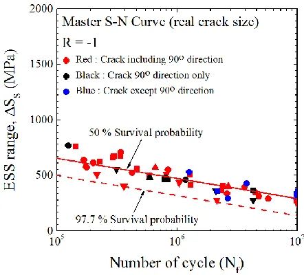
From equation 7 and Paris law, equivalent structural stress of socket welded pipe is derived. Because defect is considered as a crack, structural stress is calculated from ideal socket welded pipe and bending ratio is constant for every cases. Considering stress ratio is -1, equivalent structural stress of socket welded pipe is proposed as shown in equation 10. I(a/t, c) function is shown in Figure 10, which is determined by initial incomplete penetration geometries.
1/3 1/6 2/3 , 2 S S S a
t I c
t
From equation 10 and Figure 3, Master S – N curve of socket welded pipe is proposed in Figure 11. During procedure, real defect size is measured for every test. As a result of procedure, some cases which cases cannot measure real defect size is ignored. Master S – N curve equation for 50 % and 97.7 % reliability are calculated in equation 11 and 12.
181.06 log(
) 1559.64
S f
S
N
(37)
181.06 log(
) 1404.88
S f
S
N
(38)
Figure 10 I(a/t, c) function of socket welded pipe
CONCLUSION
To predict fatigue life of socket welded pipe with incomplete penetration defect using FE. From FE analysis, when 4 – point bending stress is applied to pipe, maximum structural stress is located at the centre of defect length and 90o crack propagation direction has maximum value compared to other directions. Also, larger defect increases structural stress, however crack propagation rate begin to decrease when crack size is over half of weld thickness.
To consider crack propagation and evaluate fatigue life, structural stress is converted to equivalent structural stress. Using Paris law and stress intensity equation from FE analysis, equivalent structural stress is derived and master S – N curve considering real incomplete penetration defect is proposed.
REFERENCES
P. Dong. (2001). “A structural stress definition and numerical implementation for fatigue analysis of welded joints,” International Journal of Fatigue, Vol.23, Issue.10, 865-876.
P. Dong, J. K. Hong, D. A. Osage, M. Prager. (2002). “Master S-N curve method for fatigue evaluation of welded components,” Welding Research Council Bulletin, Issue.474, 1-44
ABAQUS, (2013), “ABAQUS version 6.13 User’s manual”, Dassault Systèmes, SIMULIA Corp., Vélizy-Villacoublay, France