Available online: https://edupediapublications.org/journals/index.php/IJR/ P a g e | 1908
IOT Based Energy Meter Reading
M
R.
A.
RAJESH
NAIDU,
A
SSOCIA TEP
ROFESSOR,
DEPA RTM ENT OF ECEY. HEMA SAI SINDHU ,B. LOKESHWARI DEVI , T. VANDANA , V. SYAM PRASAD
B.Tech Students , Department of Electronics & Communication Engineering, Ramachandra College of Engineering, Eluru, Andhra Pradesh, India.
Abstract: The project is about making the energy meter smart by having a continuous automatic communication between the consumer’s energy meter and the utility. The energy meter reading is communicated to the utility and to the consumer via internet. NodeMcu onto which the programming (c) is uploaded is used for internet connectivity. Monitoring and keeping tracking of your electricity consumption for verification is a tedious task today since you need to go to meter reading room and take down readings. Well it is important to know if you are charged accordingly so the need is quite certain. Well we automate the system by allowing users to monitor energy meter readings over the internet. Our proposed system uses energy meter with microcontroller system to monitor energy usage using a meter. The meter is used to monitor units consumed and transmit the units as well as cost charged over the internet using WiFi connection. This allows user to easily check the energy usage along with the cost charged online using a simple web application. Thus the energy meter monitoring system allows user to effectively monitor electricity meter readings and check the billing online with ease.
I. INTRODUCTION
The internet of thing allows object to be sensed and controlled remotely across existing network infrastructure, creating opportunities for more direct integration between the physical world and computer based systems, and resulting in improved efficiency, accuracy and economic benefit.
The increasing generation needs empowered gadgets by wireless technology which includes Bluetooth, Radio Frequency Identification, Embedded sensors and many more. In that IOT technology has grown from its beginning and now presently widely using it. The electricity plays an important role in our life. Now-a-days as the consumers are increasing rapidly it became very hard to handle the electricity requirements. Without electricity it’s impossible to survive and also it is important to save the electricity loss. As the generation is increases the consumer’s requirements also increasing so in accordance with it the technology improvement is needed. So we developed the system with faster and improved technology i.e. IOT. The electricity also contains some issues like power theft. Power theft is a measure crime and it also directly affects the economy of our country. Transmission, generation and distribution of electricity include the loss of electricity. To avoid the losses we need to monitor the power consumption and losses, so that we can efficiently utilize the generated power. Meter tempering is part of power theft and also illegal crime which we can minimize. Billing is a process in general the human operator goes to every consumer’s home then providing bill it will take lot of time. To resolve these issues we developed system on the base of IOT energy meter reading.
Available online: https://edupediapublications.org/journals/index.php/IJR/ P a g e | 1909
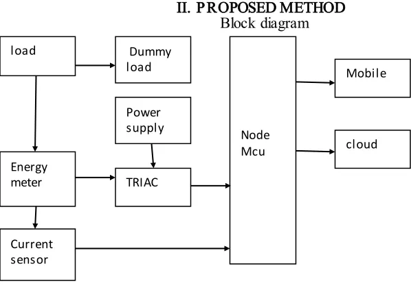
Block diagram
Figure 1: Block diagram of proposed IOT based energy meter reading
The block diagram of the project consists of controller part, theft detection part and wifi unit. Controller part consists of Node Mcu with WIFI ESP8266 for the IOT operation.
Triac , Current sensor , Energy meter these are other components present in the system.
Node Mcu is the core component of the project that connects input and outputs of the devices. The Node Mcu used is ARDUINO with WIFI module.
Initially DC power supply to give voltage to the circuit. Amplifier circuit and isolation circuits are connected with relays and load. The load and relays in this circuit represent the devices that need energy or electricity to operate and are used at homes. Energy meter is connected to Node Mcu through Triac which are used Monostable multivivrator. This gives the information to the controller about the energy consumed, bill and if any theft occur. The bill is calculated using the formula as shown below.
Bill = consumed units * 3 + 50
Once the information is sent the Node Mcu controller it will further communicate to WIFI and it will display on the LCD. Also the information is sent to the web server through wifi which is attached to Arduino controller. The information uploaded on the internet is accessed through a webpage. And the programming of the whole system is done using embedded ‘c’.
III. SYSTEM IMPLEMENTATION
The proposed IOT based Energy Meter Reading is implemented using two nodes, one on the consumer end and one for the Web server.
1) Consumer End Implementation
In this project we are using Node Mcu with WIFI ESP8266 module for the IOT operation. The project mainly focuses on the billing, and power theft.
A. NodeMCU
The NodeMCU is a part of Arduino and it’s having in built WIFI (ESP8266). And it is runs on 3.3v power and logic, and unless otherwise specified, GPIO pins are not 5v safe. The analog pin is also 1v maximum. This ESP8266 breakout has a ton of pins available, compared to the mini ESP-01 module.
When programming the breakout in the Lua or via the Arduino IDE, you can control these i/o pins to light up the LEDs ,read buttons, talk to sensors etc.
Node Mcu Power supply TRIAC Current sensor Mobile cloud Energy meter
load Dummy
Available online: https://edupediapublications.org/journals/index.php/IJR/ P a g e | 1910
B. Arduino Uno
Figure 2: Arduino Uno
Arduino is a microcontroller board and it is based on ATmega328P. Board consists of 14 digital input/output pins. Out of which 6 input pins are used as PWM outputs, 6 as analog inputs, quartz crystal of 16MHz, having USB connection, power supply jerk, an ICSP header and reset button. Simply we can connect the Arduino board to the computer using USB connection to get start. Also we can supply power to it with AC – to – DC adapter or we can use battery to get started. As we compare Arduino UNO board with other it differs from the proceeding board which doesn’t use FTDI USB – to – serial driver chip. Instead of that the ATmega8U2 is programmed as USB – to – serial converter
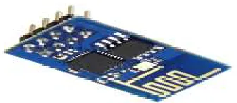
C. WIFI ESP8266
Figure 3: ESP18266 WIFI module
Wifi ESP8266 is a low cost chip with TCP/IP stack and microcontroller. In our project main importance of wifi is it performs IOT operation. The simple device is connected from microcontroller to send the information.
2) Web server
Available online: https://edupediapublications.org/journals/index.php/IJR/ P a g e | 1911
IV. RESULTS
The results of the project are shown below step by step in the form of picture repres entation.
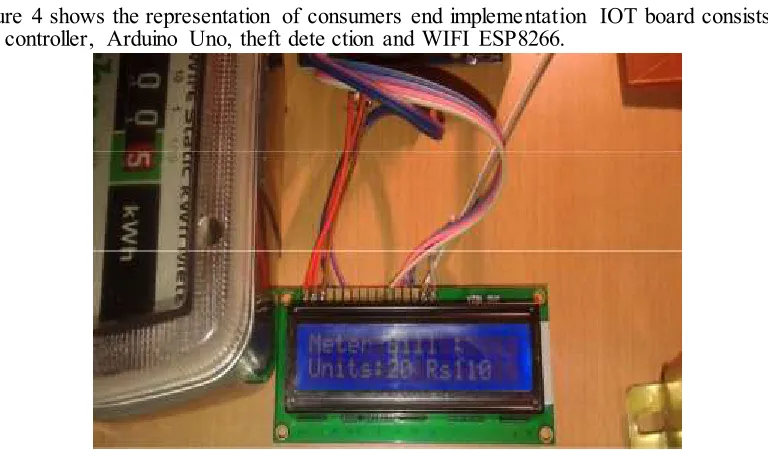
Fig ure 4: Implementation of the board
The figure 4 shows the representation of consumers end implementation IOT board consists of ARM 7 controller, Arduino Uno, theft dete ction and WIFI ESP8266.
Figure 5: LCD d isplay of energy meter bill and consumed units
Figure 5 shows LCD display of cons umed units and bill for the consumed units.
Available online: https://edupediapublications.org/journals/index.php/IJR/ P a g e | 1912 Figure 7 display of bill on web server
Figure 7 shows the bill for the consu med units on the web server with time and date.
Figu re 8: LCD display of theft detected
Figure 8 shows tamper happened in energy meter which is displayed on the LCD di splay.
Figure 9: Th eft detected part displays on the web server
V. CO NCLUSION AND FUTURE SCOPE
Conclusion
The project is mainly concentrated
Available online: https://edupediapublications.org/journals/index.php/IJR/ P a g e | 1913
electromagnetic into a digital meter. We are doing automatic reading and also connection and disconnection of meters using WIFI module. Then meter reading has come faster. It is publically available for the customers as well as for the KPTCL. Both the peoples will be using the information as per their requirements and they will be having freedom to check the bill, tampering, when the meter has been connected and disconnected before the due date. All the information will be displayed by using smart app. Finally concluding our project that we are successfully monitored the tampering i.e. seal tampering and we have read the meter bills which also be uploaded on the website using IOT concept. Overall the new things we are worked with in our project are ARM controller coupled with Arduino controller and the IOT model.
Future Scope
The project mainly aims at providing overall infrastructure of the energy meter presently used for the smart city concept. The main improvement for the future is going to make energy meter readings, tampering identification techniques, and connection and disconnection and also the pre information providing to the users all is going to happen on wifi internet. Where we are going to develop some wifi hotspots in each area through which all the energy meters are get connected and set 4 to 5 parameters which is also going to be monitored. And the overall improvement information will be providing to the energy meter i.e. KPTCL will be easy for them to handle the things. Also in future we can go with some standard apps or standard tools, where in which it makes work easy for KPTCL people by reading the meter readings faster than the fastest method. And connect and disconnect of every meters on the on – payment and non – payment that will be fast as compared to the present method.
REFERENCES
1. Internet of things (http://en.wikipedia.org/wiki/Internet-of-Things) 2. Digital.csic.es/bitstream/10261/127788/7/D-C-%20Arduino%20uno 3. ESP8266 802.11bgn Smart Device/Expressifsystems/October 2013
4. Darshan Iyer N and Dr. K A Radhakroshna Rao, IoT Based Energy Meter Reading, Theft Detection and Disconnection using PLC modem and Power Optimization, Proc of IJAREEIE, Vol 4, Issue 7, July 2015 5. Thingspeak (www.Thingspeak.co.in)