A Literature Survey Design Optimization and Analysis of Shear
Wall In High Rise Buildings
Mr.
GANGALA DILEEP KUMAR&
Mr. THULASIRAMAN.S1 PG Student, Dept. Of Structural Engineering , SKR College Of Engineering & Technology, AP
2 Asst. Professor, Dept. Of Structural Engineering, SKR College Of Engineering & Technology,
Abstract Residential Building with 19 floors is analyzed with and without shear walls for wind and earthquake loads. The Building consists of four flats for each floor and comes under zone 2. Shear walls were taken at lift and stair and corners of the building as L shape. Vertical loads, Moments, Lateral forces, Torsional moments were compared for both cases at each floor during analysis part. Optimization techniques are used to solve structural engineering problems where the most complex high rise structures using design optimization, involving both size and topological optimization is solved by considering stability, safety, response to different type of loadings. Wall-frame structure optimization is the part of project.. For this system of wall and cores they were checked for displacement, Internal Stresses and Intensities when subjected to various loadings.
KEYWORDS: Shear Walls, Optimization, Lateral Forces, Bending Moments, Torsional Moments, Storey Drifts, Maximum Displacements, Internal Stresses, Intensities.
I.INTRODUCTION
A. General
In modern civilization tall buildings have rapidly developed worldwide. Tall buildings are symbols of civilized,
congested and populated society. It certainly resembles the economic growth, the force and the image of a civilization. A Tremendous variety of field of study shapes and complicated structural layouts are designed. The design of tall buildings essentially involves an approximate analysis, conceptual design, preliminary design and what's more, advancement, to securely convey gravity and horizontal burdens. The design criterion is strength, serviceability, stability and also human comfort. The strength is satisfies by limit stresses, while serviceability is satisfies by drift limits in the range of H/300 to H/500. Stability is satisfied by sufficient safety factor against buckling and P-Delta effects. The safety factor is around 1.67 to 1.92. The human comfort aspects are satisfied by accelerations are in the range of 10 - 25 mg, where, g -acceleration due to gravity= 981cms/sec2.
buildings are determined, the structural design of high-rise buildings which checks structural safety for the individual structural members is not necessary outstanding structural ability by the use of structural software on the market. However, it is not an exaggeration to say that the performance of high-rise buildings is almost determined in the preliminary design stages which work on multifaceted examinations of the structural form and outline.
The static and dynamic structural behaviors of high-rise buildings are governed by the distributions of transverse shear stiffness and bending stiffness per each storey. The deformations of high-rise buildings are composed of the axial deformation, bending deformation, transverse shear deformation, shear-lag deformation, and torsional deformation.
Today’s tall buildings are becoming more and more slender, leading to the possibility of more sway in comparison with earlier high-rise buildings. Therefore, the time dependency of concrete has become another important factor that should be considered in analyses to have a more reasonable and economical design.
In this study we considering a 15 storey high rise building for shear wall design and
optimization by using the software E-tabs and the shear walls are arranged in such a way to resist the lateral forces in zone III
region according to Indian codes.
B. Advantages of shear wall in Skyscraper
Properly designed and detailed buildings with shear walls have very good performance in earthquakes. The shear walls are orientedin one direction, so only lateral forces in that direction can be resisted. Shear wall can be defined as structural vertical member that is able to resist combinations of shear, moment and axial load induced by lateral wind load and gravity load transferred to the wall from other structural members. The use of shear wall structure has gained popularity in high rise building construction, especially in the construction of service apartment or office/commercial tower. The overwhelming success of buildings with shear walls in resisting strong earthquakes is summarized as “we cannot afford to build concrete buildings meant to resist severe earthquakes without shear walls”. Shear wall resist to the lateral forces.
C. Objectives
1) Behavior study of 15storey high rise RCC structure with shear walls for seismic & wind loads.
2) The variation of storey drifts of the models to be studied.
3) The variation of displacement has to studied
4) Both equivalent static analysis and Response spectrum analysis are to be carried out
5) Optimum location of shear wall.
Earthquakes are occurring frequently now a day. The seismic analysis and design of buildings has traditionally focused on reducing the risk of loss of life in the largest expected earthquake. To reduce the effects caused by these earthquakes and wind loads different lateral loading systems are introduced in the structures. Position of shear walls in unsymmetrical buildings has due considerations. It is very necessary to determine efficient and ideal location of shear wall.
II.LITERATURE REVIEW
In the early 1940s when the first shear walls were introduced, their use in high rise buildings to resist lateral loads has been extensive, in particular to supplement frames that if unaided often could not be efficiency designed to satisfy lateral load requirements. The walls in a building which resist lateral loads originating from wind or earthquakes are named as shear walls at first. A large portion of the lateral load on a building is often assigned to such structural elements made of RCC
Mo and Jost (1993) predicted the seismic response of multistory reinforced concrete framed shear walls using a nonlinear model. From results it was concluded that the effect of concrete strength on the framed shear walls is significant because increasing the concrete strength from 25MPa to 35.0 MPa can cause the maximum deflection to decrease by 30% for El Centro record.
Arthur Tena-Colunga and Miguel Angel
Perez-Osornia(2005) had studied on shear deformations and said that Shear Deformations are of paramount importance in the planar two dimensional analysis of shear wall systems, both for strains and stresses, so they should be included in the analysis of such systems.
Lew et al. (2008) discussed the challenges in the selection of earthquake accelerograms for use in the seismic design of tall buildings. They suggest that in order to cover the response effects of different modes, tall buildings need to be analysed using many more ground motion accelerograms than the sets of three or seven accelerograms that are normally used in the current design practice for tall buildings
S.V. Venkatesh, H. Sharada Bai (2013)
discussed the difference in structural behavior of 10 storey basic moment resisting RC frames when provided with two different types of shear walls as lateral load resisting structural systems (LLRS) and concluded that external shear walls serve as an alternative to internal shear walls in retrofitting seismically deficient structures, particularly when it is not possible to vacate the building during retrofitting
III.METHODOLOGY
A. General
loads, is documented. Efficient model formulation and problem solution is achieved by idealizing the building as a system of frame and shear wall substructures inter-connected by floor diaphragms.
B. Method of analysis
Design of 15 storey high rise building and optimization of shear wall is done by computer aided software E-Tabs. Plan generated in Auto cad is imported and modeled in E-Tab. This model is analyzed for axial and lateral loads and the results are studied. For optimization of shear wall location shear wall is placed in three different locations and the results obtained such as displacements, drifts, storey shears are studied and compared.
IV.MODELING AND DESIGN
A. Building considerations
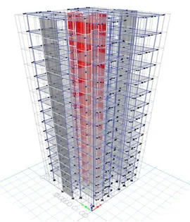
A high rise building is assumed for seismic analysis that consists of a G+14 R.C.C. residential building. The plan of the building is irregular in nature but considered as it is regular for easy analysis. The building is located in Seismic Zone III and is constructed on medium type soil. The building is 54.4m in height 18.69m in length and 18.99m in width. The important details of the structure are as follows.
B. Load considerations
Dead Load (DL) and Live load (LL) have been taken as per IS 875 (Part 1) (1987), IS 875 (Part 2) (1987) and IS 875 (Part 3)
(1987), respectively. Seismic load calculation has been done based on the IS 1893-2000 (Part 1) approach.
C. LOADS
A building is subjected to the following loads during its service life.
1) Dead Load: The dead loads in a building shall compromise of the weight of all the walls, partition walls, floors and roofs and shall include the weight of all the other permanent constructions in the building.
2) Live Load: Live loads are also called the superimposed loads and include all the moving or variable loads, due to people or occupants, their furniture, temporary stores, machinery etc. Live loads on floors shall compromise of all loads other than the dead loads. The various live loads acting on the different floors are given in IS 875: 1998
3) Earthquake Load: EQ load acts on the structure during earthquake. It will act horizontally on the structure. It is also called asseismic force.
The following load combinations are considered as per IS codes and the model is analyzed for critical load condition.
a) 1.5(DL+LL)
b) 1.5(DL+LL+SIDL)
c) 1.2(DL+LL+SIDL+WL)
d) 1.2(DL+LL+SIDL-WL)
e) 1.5(DL+SIDL+WL)
f) 1.5(DL+SIDL-WL)
h) 0.9(DL+SIDL)-1.5WL
i) 1.2(DL+LL+SIDL+EQ-X)
j) 1.2(DL+LL+SIDL-EQ-X)
k) 1.2(DL+LL+SIDL+EQ-Y)
l) 1.2(DL+LL+SIDL-EQ-Y)
m) 1.5(DL+SIDL+EQ-X)
n) 1.5(DL+SIDL-EQ-X)
o) 1.5(DL+SIDL+EQ-Y)
p) 1.5(DL+SIDL-EQ-Y)
q) 0.9(DL+SIDL)+1.5EQ-X
r) 0.9(DL+SIDL)-1.5EQ-X
s) 0.9(DL+SIDL)+1.5EQ-Y
t) 0.9(DL+SIDL)-1.5EQ-Y
u) 1.5(DL+SIDL)
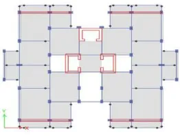
4) Mathematical model: The three
dimensional view and plan of the building are showed in figure 4.1and 4.2 respectively.
Fig 4.1.-3D view of the building
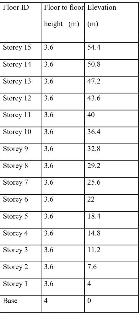
Table 4.1: floor to floor height of the building
1) Optimization of shear wall: The present work deals with the study of effect of seismic and wind loading on placement of shear walls in 15 storey high rise building at different locations. The residential high rise building is analyzed for earthquake force and wind force. Shear wall is placed at different positions of building and optimization of shear wall has been studied. The optimum location for the particular case is found and compared with the rigid frame. The analysis is carried out by using standard package ETABS.
The different cases considered are:
Case A - without shear wall
Case B – shear wall at corners
Case C – shear wall parallel to X-axis
Case D – shear wall parallel to Y-axis Floor ID Floor to floor Elevation
height (m) (m)
Storey 15 3.6 54.4
Storey 14 3.6 50.8
Storey 13 3.6 47.2
Storey 12 3.6 43.6
Storey 11 3.6 40
Storey 10 3.6 36.4
Storey 9 3.6 32.8
Storey 8 3.6 29.2
Storey 7 3.6 25.6
Storey 6 3.6 22
Storey 5 3.6 18.4
Storey 4 3.6 14.8
Storey 3 3.6 11.2
Storey 2 3.6 7.6
Storey 1 3.6 4
Fig 4.3: Model without shear wall
Fig 4.4:Model with shear wall at corner
Fig 4.5:Model with shear wall parallel to x-axis
Fig 4.6: Model with shear wall parallel to y-axis
2) Displacement: According to IS
456:2000, the allowable displacement is 0.04H (H/250) where h is the storey height and H is thetotal height of the building, for a partial safety factor of 1.0.
3) Design
D. Seismic coefficient method (static method)
Seismic analysis of most structures is still carried out on the assumptions that the lateral (horizontal) force is equivalent to the actual (dynamic) loading. This method is usually conservation for low to medium-height buildings with a regular conformation. Static method values:
Direction and Eccentricity
Direction = Multiple
Eccentricity Ratio = 5% for all diaphragms
Factors and Coefficients:
Seismic Zone Factor, Z [IS Table 2]
Response Reduction Factor, R [IS Table 7]
Site Type [IS Table 1] = II
Seismic Response
Spectral Acceleration Coefficient, Sa /g [IS
6.4.5]
R = 5
I = 1
S
g = 0.990338
E. Response spectrum analysis
According to the Indian code in the response spectrum method, the response of a structure during an earthquake is obtained directly from the earthquake response (or design) spectrum. This procedure gives an approximate peak response, but this is quite accurate for structural design applications. The responses of different modes are combined to provide an estimate of total response of the structure using modal combination methods such as complete quadratic combination (CQC), square root of sum of squares (SRSS), or absolute sum
(ABS) method. Response spectrum method of analysis should be performed using the design spectrum specified or by a site.
1) Dynamic analysis: Dynamic analysis
done by E-tabs by giving scale factor initially as 1000 and analysis is done by trial anderror method. The ratio of static by dynamic will get the scale factor and the initial scale factor is replaced by obtained scale factor.
F. Wind Load Calculation Exposure
Parameters: Structure Class = Class B
Terrain Category = Category 2
Wind Direction = 0:90 degrees
Top Story = Story15
Bottom Story = Base
Include Parapet = No
Factors and Coefficients:
Risk Coefficient, k1 [IS 5.3.1]
k = 1
Topography Factor, k3 [IS 5.3.3]
k = 1
Design Wind Speed, Vz [IS 5.3]
V = V k k k
Lateral Loading
p = 0.6V
V.RESULTS AND DISCUSSIONS
The seismic analysis of reinforced concrete frame structure is done by both static and dynamic analysis to determine and compares the base shear. Dynamic analysis done by E-tabs by giving scale factor initially as 1000 and analysis is done by trial and error method. The ratio of static by dynamic will get the scale factor and the initial scale factor is replaced by obtained scale factor. From the lateral stability of the building values obtained by E-tabs for static and dynamic analysis the scale factor assumed in dynamic analysis is satisfied.
Base shear is affected marginally with placing of shear wall. The base shear is increasing by adding shear wall due to increase in shear wall of the building. Provision of shear wall generally results in reducing the displacement because the shear walls increase the stiffness of building. The better performance for structure with shear wall has low displacement. It has been seen from Table that the top deflection has not exceeded the permissible deflection, i.e. 0.004 times the total height of the building as per IS 1893 (Part 1) (2002) clause No.7.11.
VI.CONCLUSION
A. From the study of literature review it is clear to say that due to the presents of shear walls and their location in the
structure place a major role in construction of a building.
B. The results obtained from the study shows that shear wall arrangement gives best result towards the building elements like storey displacement, inter-storey drift, base shear, lateral forces compared to bare frames.
C. The model with shear wall placed at corners of the building shows less displacements and drifts and thus considered as optimum location.
D. In this present paper from the study of literature paper the structure is constructed by shear walls at different locations. It has been observed that the top deflection was reduced and reached within the permissible deflection after providing the shear walls at possible failure positions such as the shorter directions.
E. Increasing axial load level decreases R factor. So design base shear will be increased and moment of inertia of the section should be increased. In other hand, the lesser the axial load, the much more cross sectional area.
F. Confinement of concrete in shear walls is a good way to provide more level of ductility and getting more stable behavior. So, the designer would be allowed to bring up the level of axial stresses to have a reasonable design.
G. Not only main walls are assumed to carry seismic loads, but also they are going to bear a significant percentage of gravity loads.
provided in this paper for 15 storey high rise building.
VII. SCOPE FOR FUTURE WORK
Today’s tall buildings are becoming more and more slender, leading to the possibility of more sway in comparison with earlier high-rise buildings. We can achieved minimize displacement wind forces and seismic forces, also the structure should be stable and we need to another case study of offshore structures and consider water pressure how it will occur& also consider ETAB software.
REFERENCES
[1] Bush T. D., et al, “Behavior of RC frame strengthened using structural systems”, Journal of Structural Engineering, Vol. 117, No.4, April, 1991.
[2] Shahzadjamilsardar, et al, “Effects of change in shear wall location on storey drift of 20 stored multi storey building subjected to lateral loads”, IJIRSET-2013.
[3] Himalee Rahangdale, et al, “Design and Analysis of Multi storied Building with Effect of Shear Wall”, Vol. 3, Issue 3, May-Jun 2013, pp.223- 232. 2.
[4] Patil S.S., et al, “Equivalent static analysis of high rise building with different lateral load resisting systems”, IJERT-2013.
[5] Kevadkar. M.D. et al, “Lateral Load Analysis of R.C.C. Building”, International Journal of Modern Engineering Research, IJMER Vol.3, Issue.3, May-June. 2013 pp-1428-1434 ISSN: 2249- 6645.
[6] Duggal S.K, “Earthquake Resistant Design of Structures”, Oxford University Press, New Delhi 2010.
[7] IS 13920:1993, “Ductile detailing of reinforced concrete structure subjected to seismic forces-code of practice”.
[8] IS: 456-2000: “code of practice for plain and reinforced concrete”.
[9] IS: 875(part 1-5): “code of practice for structural safety of building loading standards”.
[10] IS 1893(part-1):2002, “Criteria for earthquake resistance design of structures”.
[11] SP: 16: “Design aids for reinforced concrete”.
Author’s Details
Mr. GANGALA DILEEP
KUMAR received Btech
in Civil Engineering from Jagan’s College of Engineering and Technology affiliated to the Jawaharlal Nehru technological university Anathapur in 2015, and pursing M. Tech in Structural Engineering from SKR College of Engineering affiliated to the Jawaharlal Nehru technological university Anantapur in 2016, respectively.