Design of a Pyramidal Horn Antenna with Low
E
-Plane Sidelobes
Using Transformation Optics
Shaghayegh Shahcheraghi* and Alireza Yahaghi
Abstract—Transformation optics is a convenient way to control the pattern of electromagnetic fields. In this paper, using a novel transformation, we propose the design procedure of a horn antenna having low backlobe and sidelobe levels in itsE-plane. By applying conformal transformation, the rectangular horn proposed in this paper can be realized with isotropic materials. This proposed antenna can be easily implemented by both ordinary dielectric materials and isotropic graded refractive index (GRIN) materials. In the first proposed design, in addition to the isotropy, homogeneity is furthermore introduced into the horn, and only four kinds of isotropic materials are required throughout. In the second design, it is demonstrated that the designed structure can also be implemented by graded photonic crystals (GPCs) operating in metamaterial regime. They have low loss as well as broad frequency band and are easy to implement. Simulation results are presented to validate the design approach.
1. INTRODUCTION
Horn antennas have been improved considerably by incorporating technological advances over the past few decades [1]. The conventional rectangular horn antennas have high sidelobes in their E-plane (on-axis plane containing the E field vector), which is a result of the uniform electric aperture field distribution in this plane.
Some efforts have been made to reduce the sidelobe levels of horn antennas [2–9]. State-of-the-art techniques for implementing horn antennas having low sidelobe levels are corrugating the interior surfaces [2–4], which yields a structure more bulky and difficult to fabricate, applying longitudinal metallic vanes or trifurcations inside the horn to step the electric field in the E plane [5], using optical ray technique [6], employing dispersion engineering of metamaterial properties [7], and design of metasurfaces [8] to taper the aperture distribution. A new technique was recently proposed, which uses transformation optics [9] in order to design a horn antenna with lowH-plane sidelobes.
Transformation optics (TO) offers a great opportunity to control the field distribution by assigning material spatial properties. This technique is based on the fact that the form of Maxwell’s equations remains unchanged under coordinate transformation [10–12] if the elements of constitutive tensors (the electric permittivity and magnetic permeability) are expressed as a function of space coordinates. It means that by applying the coordinate transformation to the constitutive tensor in a manner suggested by the form invariance of Maxwell’s equations [13], the medium characteristics are obtained, and then by realizing these constitutive parameters in the new coordinate, the behavior of the electromagnetic waves would be the same as that of EM waves in the original coordinates. Therefore, transformation optics can be an effective way for controlling the EM wave.
Constitutive parameters obtained by TO are usually very complicated and cannot be realized easily [13, 14]. That’s why the first implementation of r and μr tensors obtained by TO, was achieved
Received 9 March 2015, Accepted 23 October 2015, Scheduled 26 October 2015 * Corresponding author: Shaghayegh Shahcheraghi ([email protected]).
suffer from limited bandwidths of operation and intrinsic losses. As a result, obtaining devices with acceptable performance using TO remains still a challenging issue.
Recently, Pendry and Li have suggested a method which relies on optimization techniques [41] in order to make the realization of constitutive parameters much easier. According to this method, it is enough to accomplish refractive index of the material instead of realization of bothr andμr separately.
Also, it may be possible to achieve an isotropic medium by applying conformal transformation [42, 43]. This way, the material could be realized only with natural dielectrics, and not only it would be much easier to implement, but also the problem of bandwidth limitation is removed.
In this paper, a novel transformation is presented which results in the design of a nonmagnetic and isotropic pyramidal horn antenna having low sidelobes and backlobes in its E-plane. In addition to the isotropy, in our first design, homogeneity is furthermore introduced into the antenna, and only four kinds of isotropic materials are required throughout. In our second design, we also use a graded photonic crystal to realize refractive index of the original inhomogeneous material. This design, which results in low loss and wide frequency band, is based on air holes drilled on a homogeneous dielectric material. Compared to the previous horn antennas with low sidelobes [2–9], our designs are less demanding, which are thus easier to realize. Therefore, our approach provides a more advantageous recipe for the practical realization of pyramidal horn antennas with low E-plane sidelobes based on coordinate transformation. The simulation results of the designed antenna are also presented.
2. DESIGN OF THE HORN ANTENNA WITH LOW SIDELOBES
In pyramidal horn antennas, nearly uniform distribution of electric aperture field in theE-plane results in high sidelobe levels in this plane. Furthermore, studies have shown that the main source of backlobes is the field diffracted by theE-plane edges.
Squeezing field distribution in theE-plane of the horn antenna forces the electric field components normal to the E-plane walls to zero. As a result, the illumination from E-plane walls is decreased, and reduction in sidelobe levels and backlobe levels in theE-plane would simultaneously be achieved. To realize this idea, we employ optical conformal transformation. The main advantage of conformal mapping is that the obtained media is isotropic, so it can be implemented by ordinary dielectrics.
In this work, WRD250 horn antenna is used with WR187 as its input waveguide. The dimensions of the 3D structure are shown in Fig. 4.
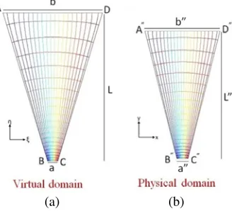
Based on the size of the horn antenna, we consider the left quadrilateral in Fig. 1 as the virtual space in which a= 2.21488 cm, b= 21.5 cm, andL = 32.5 cm. This figure is mapped conformally to a physical space with a = 2.21488 cm,b= 15 cm, andL= 25.5 cm. b andL have been selected in a way that the conformal module (M) of the horns in both virtual and physical spaces is the same.
According to the Riemann mapping theory, a conformal transformation that maps the vertices A, B, C, and D onto the cornersA,B,C, andD(Fig. 1) respectively, always exists. In order to simplify the mapping from virtual space to physical space, a rectangle with the same conformal module (M) is considered as an intermediate region. Since only one parameter varies along each side of a rectangle, determination of the conformal mapping is reduced to solving Laplace’s equations subject to boundary conditions by a normal PDE solver [43]. For convenience, we have applied TO in a two-dimensional problem with incident transverse magnetic (TM) field resembling the E-plane of a real horn antenna excited byT E10mode. The notations (ξ,η), (u, v), and (x, y) indicate the Cartesian coordinates in the
virtual, intermediate, and physical space, respectively. In the first step, the virtual space is mapped into the intermediate space. The mathematical description of this transformation is characterized by the Jacobean matrix Λ defined by Λii = ∂ui
∂ξi (u
(a) (b)
Figure 1. Procedure of conformal mapping. (a) The determined quadrilateral in virtual free space. (b) The antenna resulting from conformal mapping. (Contours in each domain are obtained by solving Laplace’s equations).
Jacobian matrix elements should satisfy Cauchy-Riemann conditions everywhere in the virtual domain:
uξ=vη, uη =−vξ (1)
Employing partial differentiation on both sides of these equations, the following Laplace’s equations for analytical functions u(ξ,η) and v(ξ,η) are achieved:
uξξ+uηη= 0, vξξ+vηη = 0 (2)
The mapping Jacobean matrix Λ can be obtained by solving Laplace’s Equations (2) in the virtual domain subject to the boundary conditions along the four straight lines of the rectangle (ξ = 0, a and
η= 0, M a).
Once the Jacobean matrix Λ is acquired and the field polarization is taken into account, the properties of the intermediate medium can be calculated by:
μ= μr
detΛ =μr/[(uξ)
2+ (
uη)2], = 1 (3)
where μr is the permeability of the original domain. Equation (3) represents that the conformally
transformed medium is an isotropic material. The derivation of this equation and its general form for the transformed media are presented in [12]. Considering that the intermediate domain is a rectangle, Equations (2) can be solved separately by the following standard Neumann and Dirichlet boundary conditions:
u|AB = −0.011, u|CD = 0.011,n· ∇u|BC,AD= 0 (4)
v|BC = 0, v|AD = 0.022M,n· ∇v|AB,CD= 0 (5)
where vectornis the outward normal to the surface boundaries and the conformal moduleM is obtained by M =(a1)(CD|∂u∂n|ds) [44]. The properties of the material in the intermediate space (n(u, v)), is calculated by interpolation of the obtained refractive index in the virtual domain (n(ξ,η) =
μr
detΛ),
considering that virtual space is empty (μr= 1).
The Jacobian matrix Γii = ∂xi
∂ui(xi = x, y and ui
= u, v) indicating the transformation from physical space to intermediate space could be calculated in the same way using the following equations:
uxx+uyy= 0, vxx+vyy = 0 (6)
u|AB = −0.011, u|CD = 0.011, n· ∇u|BC,AD= 0 (7)
v|BC = 0, v|AD = 0.022M, n· ∇v|AB,CD= 0 (8)
By calculating u(x, y) and v(x, y) and knowing the material properties of the intermediate domain (n(u, v)), the refractive index in the physical space is obtained by:
n(x, y) =
μr
detΛ−1 =n
(u, v)∗[(u
realize these values, metamaterials, which are usually resonant structures, can be used. In order to have a non-dispersive antenna and large bandwidth, it is preferable to replace all indices smaller than unity by 1. This approximation leads to an acceptable reduction in antenna performance.
The obtained refractive index distribution requires magnetic permeability realization. Since most accessible natural materials do not have a strong magnetic response, it is usually hard to implement a magnetic material with an arbitrary permeability distribution.
To overcome this issue, we employ the reduced parameter approximation [45]. According to this approximation, if one requires only that power follows through the desired paths, then only the refractive index is needed to be controlled in the material. The reduced parameter approximation does this by setting μred = 1, to facilitate the material fabrication, and red=μ, to maintain the refractive index
profile in the material. After employing these refinements, for the practical realization of the design, normal dielectrics, or dielectric rods with spatially varying radii [46] can be used. They have low loss, wide frequency band and are easy to implement. In this work, in addition to using dielectrics to
Figure 2. Continuous and discrete profile of the refractive index for the proposed antenna (at 7 GHz).
(a) (b)
realize this refractive index distribution, the method presented in [46] is also applied, which is a general technique to realize isotropic GRIN media by two-dimensional graded photonic crystals.
3. IMPLEMENTATION OF THE HORN ANTENNA WITH LOW SIDE LOBE LEVELS USING DIELECTRIC MATERIALS
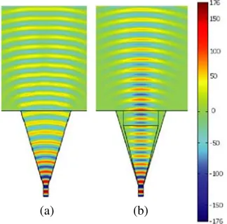
In this section, in order to illustrate the feasibility of the proposed antenna, the full-wave simulations are performed using HFSS. First, as fields are compressed as seen in Fig. 3, it can be inferred that the materials in the corners do not have a noticeable effect on the field distribution. Hence, we put the refractive index of all corner sections equal to 1.4, which is the refractive index of their neighbouring material. Therefore, as illustrated in Fig. 2, the refractive index values of the designed antenna would be between 1 and 1.4.
In this step, an appropriate division of the original refractive index distribution shown in Fig. 2, is achieved by using COMSOL Multiphysics 3.5. According to this division the designed antenna can be implemented with only four types of isotropic materials. This designed antenna is demonstrated in Fig. 4.
Figure 4. Implementation of the designed antenna with discrete dielectric materials.
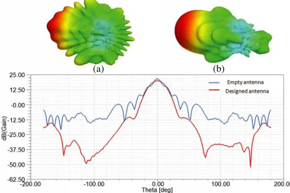
The E-plane radiation patterns of a hollow horn antenna and the designed horn antenna are compared in Fig. 5. As it can be seen, the first sidelobe level and the backlobe level (in the E-plane) have been reduced about 25 dB and 15 dB, respectively.
(a) (b)
(a) (b)
Figure 6. Electric field distribution in theE-plane of (a) the hollow horn antenna and (b) the designed horn antenna .
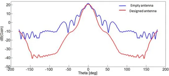
As shown in Fig. 7, the H-plane radiation patterns of the hollow and the designed horn antennas with four dielectric materials are approximately the same while the backlobe level is improved.
Figure 7. H-plane radiation patterns of the hollow horn antenna (blue) and the designed antenna (red) at 7 GHz.
The simulated patterns of the designed antenna at 5 GHz and 4 GHz are represented in Fig. 8. These simulated results demonstrate that the proposed method reduces the E-plane sidelobe level of the antenna at 4 GHz and 5 GHz about 14 dB and 20 dB, respectively.
(a) (b) (a) (b)
4. IMPLEMENTATION OF THE HORN ANTENNA USING GRADED PHOTONIC CRYSTALS
In this paper a graded photonic crystal (GPC) is used for implementation of the obtained refractive index distribution. GPCs consist of dielectric rods with spatially varying radii. They can be described with spatially varying effective index, so they can be regarded as low-loss broadband graded dielectric metamaterials. The Maxwell-Garnett effective medium theory is used to calculate the rods radii [46]. The designed non-dispersive refractive index distribution is approximated by a discrete form. In this form, each ij-cell is a square of side d = 7.5 mm with the refractive index (n(xi, yi)) of nij. For TM
polarization, the rods radii can be calculated using [46]:
rij =d
(host−n2ij)(host+rod)
π(host+n2ij)(host−rod)
(10)
In this work, in order to implement the designed index profile (nmin = 1, nmax = 1.4), an array of
air holes shown in Fig. 9 are generated by drilling in Teflon (a homogenous dielectric material) with refractive index equals to 1.41 (host = 2 and rod = 1). Teflon with refractive index equals to 1.41
is selected as a substrate, so that, as shown in Fig. 9, the holes created in the top part of the horn antenna with refractive index (n)1.4, can be omitted. Simulation result, which is performed by CST, is demonstrated in Fig. 10. It can be seen that the first sidelobe level is less than−30 dB and backlobe level is −10 dB. The comparison between Fig. 5 and Fig. 10 reveals that the gain of the metamaterial antenna realized with GPCs is about 0.7 dB more than that of the designed antenna with discrete dielectric sections. A very good return loss as shown in Fig. 11 is also achieved over the entire 4–8 GHz band.
Figure 9. Implementation of the profile with the graded photonic crystals.
Figure 11. Return loss of the horn antennas implemented with dielectric materials (red) and with graded photonic crystals (green).
5. CONCLUSION
In conclusion, we have proposed an advanced optical conformal transformation that uses homogeneous, isotropic, nonmagnetic materials to decrease the E-plane backlobe and the E-plane sidelobe levels of a pyramidal horn antenna. The simulation results demonstrate that the sidelobe and backlobe levels of the designed antenna have been reduced about 25 dB and 15 dB in the E-plane, respectively. This noticeable reduction in sidelobe levels and backlobe levels is achieved by compressing the electric field in theE-plane of the horn antenna using transformation optics. In this paper, both ordinary dielectrics and graded photonic crystals having wide bandwidth and low loss are used for the design implementation. The simulation results illustrate high performance of the proposed metamaterial antenna, which is easily realizable, in a wide frequency range. By applying this method on different pyramidal horn antennas, considerable reduction in their E-plane backlobe and sidelobe levels would be achieved.
REFERENCES
1. Balanis, C. A., Antenna Theory: Analysis and Design, John Wiley and Sons, 2012. 2. Olver, A. D.,Corrugated Horns for Microwave Antennas, IET, 1984.
3. Narasimhan, M. and V. Rao, “Radiation from wide-flare corrugatedE-plane sectoral horns,”IEEE Transactions on Antennas and Propagation, Vol. 22, 603–608, 1974.
4. Zaghloul, A. I. and T. Anthony, “E-plane flared rectangular corrugated horn for tapered aperture,”
IEEE Antennas and Propagation Society International Symposium, 1–4, 2008.
5. Peace, G. M. and E. Swartz, “Amplitude compensated horn antenna,” Microwave J, Vol. 7, 66, 1964.
6. Ata, O., T. Benson, and A. Marincic, “Application of optical ray technique to the design of short microwave horn antennas with low side lobe levels,” IEE Proceedings H (Microwaves, Antennas and Propagation), 81–88, 1990.
7. Lier, E., D. H. Werner, C. P. Scarborough, Q. Wu, and J. A. Bossard, “An octave-bandwidth negligible-loss radiofrequency metamaterial,” Nature Materials, Vol. 10, 216–222, 2011.
8. Wu, Q., C. P. Scarborough, D. H. Werner, E. Lier, and X. Wang, “Design synthesis of metasurfaces for broadband hybrid-mode horn antennas with enhanced radiation pattern and polarization characteristics,” IEEE Transactions on Antennas and Propagation, Vol. 60, 3594–3604, 2012. 9. Aghanejad, I., H. Abiri, and A. Yahaghi, “Design of high-gain lens antenna by gradient-index
metamaterials using transformation optics,” IEEE Transactions on Antennas and Propagation, Vol. 60, 4074–4081, 2012.
11. Teixeira, F. L. and W. Chew, “Lattice electromagnetic theory from a topological viewpoint,”
Journal of Mathematical Physics, Vol. 40, 169–187, 1999.
12. Leonhardt, U. and T. G. Philbin, “Transformation optics and the geometry of light,” Progress in Optics, Vol. 53, 69–152, 2009.
13. Leonhardt, U. and T. G. Philbin, “General relativity in electrical engineering,” New Journal of Physics, Vol. 8, 247, 2006.
14. Milton, G. W., M. Briane, and J. R. Willis, “On cloaking for elasticity and physical equations with a transformation invariant form,”New Journal of Physics, Vol. 8, 248, 2006.
15. Pendry, J. B., D. Schuring, and D. R. Smith, “Controlling electromagnetic fields,”Science, Vol. 312, No. 5781, 1780–1782, 2006.
16. Schurig, D., J. J. Mock, B. J. Justice, S. A. Cummer, J. B. Pendry, A. F. Starr, and D. R. Smith, “Metamaterial electromagnetic cloak at microwave frequencies,” Science, Vol. 314, No. 5801, 977– 980, 2006.
17. Cai, W., U. K. Chettiar, A. V. Kildishev, and V. M. Shalaev, “Optical cloaking with metamaterials,” Nature photonics, Vol. 1, 224–227, 2007.
18. Cheng, Q., W. X. Jiang, and T.-J. Cui, “Investigations of the electromagnetic properties of three-dimensional arbitrarily-shaped cloaks,” Progress In Electromagnetics Research, Vol. 94, 105–117, 2009.
19. Lai, Y., J. Ng, H. Chen, D. Han, J. Xiao, Z.-Q. Zhang, and C. Chan, “Illusion optics: The optical transformation of an object into another object,” Physical Review Letters, Vol. 102, 253902, 2009. 20. Hu, J., X. Zhou, and G. Hu, “Design method for electromagnetic cloak with arbitrary shapes based
on Laplace’s equation,”Optics Express, Vol. 17, 1308–1320, 2009.
21. Chang, Z., X. Zhou, J. Hu, and G. Hu, “Design method for quasi-isotropic transformation materials based on inverse Laplaces equation with sliding boundaries,”Optics Express, Vol. 18, 6089–6096, 2010.
22. Roberts, D., M. Rahm, J. Pendry, and D. Smith, “Transformation-optical design of sharp waveguide bends and corners,”Applied Physics Letters, Vol. 93, 251111, 2008.
23. Donderici, B. and F. L. Teixeira, “Metamaterial blueprints for reflectionless waveguide bends,”
IEEE Microwave and Wireless Components Letters, Vol. 18, 233–235, 2008.
24. Schmiele, M., V. S. Varma, C. Rockstuhl, and F. Lederer, “Designing optical elements from isotropic materials by using transformation optics,” Physical Review A, Vol. 81, 033837, 2010. 25. Zhang, K., F. Meng, Q. Wu, J.-H. Fu, and L.-W. Li, “Waveguide connector constructed by normal
layered dielectric materials based on embedded optical transformation,”EPL (Europhysics Letters), Vol. 99, 47008, 2012.
26. Mola, M. and A. Yahaghi, “Design of a broadband right-angled bend using transformation optics,”
Progress In Electromagnetics Research C, Vol. 56, 183–193, 2015.
27. Rahm, M., D. Schurig, D. A. Roberts, S. A. Cummer, D. R. Smith, and J. B. Pendry, “Design of electromagnetic cloaks and concentrators using form-invariant coordinate transformations of Maxwells equations,”Photonics and Nanostructures-fundamentals and Applications, Vol. 6, 87–95, 2008.
28. Jiang, W. X., T. J. Cui, Q. Cheng, J. Y. Chin, X. M. Yang, R. Liu, and D. R. Smith, “Design of arbitrarily shaped concentrators based on conformally optical transformation of nonuniform rational B-spline surfaces,” Applied Physics Letters, Vol. 92, 264101, 2008.
29. Zhang, K., Q. Wu, J.-H. Fu, and L.-W. Li, “Cylindrical electromagnetic concentrator with only axial constitutive parameter spatially variant,” JOSA B, Vol. 28, 1573–1577, 2011.
30. Jiang, W. X., T. J. Cui, H. F. Ma, X. Y. Zhou, and Q. Cheng, “Cylindrical-to-plane-wave conversion via embedded optical transformation,” Applied Physics Letters, Vol. 92, 261903, 2008.
31. Kong, F., B.-I. Wu, J. A. Kong, J. Huangfu, S. Xi, and H. Chen, “Planar focusing antenna design by using coordinate transformation technology,” Applied Physics Letters, Vol. 91, 253509, 2007. 32. Zhang, J., Y. Luo, H. Chen, and B.-I. Wu, “Manipulating the directivity of antennas with
37. Liu, R., C. Ji, J. Mock, J. Chin, T. Cui, and D. Smith, “Broadband ground-plane cloak,”Science, Vol. 323, 366–369, 2009.
38. Shelby, R. A., D. R. Smith, and S. Schultz, “Experimental verification of a negative index of refraction,” Science, Vol. 292, 77–79, 2001.
39. Klein, M., C. Enkrich, M. Wegener, C. Soukoulis, and S. Linden, “Single-slit split-ring resonators at optical frequencies: Limits of size scaling,” Optics Letters, Vol. 31, 1259–1261, 2006.
40. Shalaev, V. M., “Optical negative-index metamaterials,” Nature Photonics, Vol. 1, 41–48, 2007. 41. Li, J. and J. Pendry, “Hiding under the carpet: A new strategy for cloaking,” Physical Review
Letters, Vol. 101, 203901, 2008.
42. Landy, N. I. and W. J. Padilla, “Guiding light with conformal transformations,” Optics Express, Vol. 17, 14872–14879, 2009.
43. Ma, Y., N. Wang, and C. Ong, “Application of inverse, strict conformal transformation to design waveguide devices,” JOSA A, Vol. 27, 968–972, 2010.
44. Henrici, P., Applied and Computational Complex Analysis, Discrete Fourier Analysis, Cauchy Integrals, Construction of Conformal Maps, Univalent Functions, Vol. 3, John Wiley and Sons, 1993.
45. Landy, N., Y. Urzhumov, and D. R. Smith, “Quasi-conformal approaches for two and three-dimensional transformation optical media,” Transformation Electromagnetics and Metamaterials, 1–32, Springer, 2014.