Numerical Constructions of Testing Functions for Improving the
Accuracy of MFIE and CFIE in Multi-Frequency Applications
Barı¸scan Karaosmano˘glu, A¸skın Altınoklu, and ¨Ozg¨ur Erg¨ul*
Abstract—We present a new approach based on numerical constructions of testing functions for improving the accuracy of the magnetic-field integral equation (MFIE) and the combined-field integral equation (CFIE) with low-order discretizations. Considering numerical solutions, testing functions are designed by enforcing the compatibility of the MFIE systems with the accurate coefficients obtained by solving the electric-field integral equation (EFIE). We demonstrate the accuracy improvements on scattering problems, where the testing functions are designed at a single frequency and used in frequency ranges to benefit from the design procedure. The proposed approach is easy to implement by using existing codes, while it improves the accuracy of MFIE and CFIE without deteriorating the efficiency of iterative solutions.
1. INTRODUCTION
Recently, the main focus of the studies on the accuracy of the magnetic-field integral equation (MFIE) for low-order discretizations of perfect conductors has shifted to a proper choice of the testing functions [1], instead of a complete change of the basis and testing functions [2–6]. For example, it is shown that using the rotated Buffa-Christiansen (nBC) functions [7] instead of the conventional Rao-Wilton-Glisson (RWG) functions [8] can significantly improve the accuracy of MFIE to the levels of the electric-field integral equation (EFIE). The improvement can be explained by two favorable properties of the nBC functions, i.e., being curl-conforming similar to the rotated RWG (nRWG) functions and well-testing the identity operator similar to the RWG functions. Modifying the well-testing functions is much easier than changing both basis and testing functions. Nevertheless, the application of the nBC functions still need barycentric refinements, and practically, reimplementations of existing solvers based on the RWG discretizations.
While testing functions are defined analytically, they are often used numerically by employing a number of integration points on testing domains. Hence, at the implementation level, testing functions are reduced to a set of testing vectors with proper weights that are combinations of integration weights and the values of the used testing functions. Considering that the accuracy of MFIE heavily depends on the choice of the testing functions, it may be possible to select (and even optimize) the testing vectors numerically such that the accuracy of MFIE is improved, without deriving any analytical expression for the testing functions. In this study, we show that this approach is feasible and such numerical testing functions can be designed and constructed based on the compatibility of MFIE systems with the corresponding EFIE solutions. The designed testing functions provide more accurate results for both MFIE and the combined-field integral equation (CFIE) that is more popular for closed conductors. The proposed numerical approach and its advantages for multi-frequency applications are demonstrated on two different scattering problems.
Received 31 May 2016, Accepted 4 October 2016, Scheduled 19 October 2016
* Corresponding author: ¨Ozg¨ur Erg¨ul ([email protected]).
2. NUMERICAL CONSTRUCTION OF TESTING FUNCTIONS
Discretizations of EFIE, MFIE, and CFIE using the RWG functions lead to N ×N matrix equations in the form of
¯
ZE,M,C·aE,M,C=wE,M,C, (1)
where aE = aM = aC mostly due to the inaccuracy of MFIE [9]. In order to design more suitable testing functions for MFIE, we consider a total of P systems {Z¯Mp ,wMp } with p = 1,2, . . . , P, where each system is formed by a single-point testing. The integration points can be selected in accordance with a Gaussian quadrature rule. Specifically, well-known integration rules can be used to determine the testing locations, i.e., where to test the boundary conditions. At the same time, we also need to determine the testing directions, i.e., the directions to project the vector field intensities. For this purpose, we employ templates based on known functions, e.g., RWG and/or nRWG. Then, our aim is to find the most suitable βp forp= 1,2, . . . , P in
P
p=1
βpZ¯Mp ·aE=
P
p=1
βpwMp −→
P
p=1
βpyp = 0, (2)
whereyp =wMp −Z¯Mp ·aE. This can be performed by solving
¯ YN×P
d1×P
·βP×1=
0N×1
d
, (3)
where
¯
YN×P = [ y1 y2 . . . yP ] (4)
βP×1 = [ β1 β2 . . . βP ]T (5)
d1×P = [ d d . . . d ] (6) and T represents the transpose. The constant d= 0 is used to avoid the trivial null solution, and its value is selected by balancing the elements inY, e.g.,¯
d= 1
N P N i=1 P j=1
|Y¯N×P[i, j]|. (7)
The overdetermined system in Eq. (3) can be solved efficiently via normal equations, i.e., by a direct solution of a P×P matrix equation. Specifically, we solve
¯
YHP×N dTP×1 ·
¯
YN×P d1×P
·βP×1= Y¯PH×N dTP×1 ·
0N×1
d
, (8)
where H represents the conjugate transpose. Once the set of values βp are found, they can be used
to construct the designed MFIE system that can be employed alone or further combined with EFIE to generate a CFIE system. The overall combination of the testing integration points, the templates (RWG and/or nRWG), and the values of βp corresponds to the overall testing function, which can be
represented only numerically. The values ofβp are allowed to be complex, leading to a complex testing
function as opposed to the conventional RWG and BC functions. Finally, we note that the design procedure described above should be avoided when EFIE currents are contaminated with internal resonances. These resonances may also lead to huge numbers of iterations for EFIE, making the numerical construction inefficient. However, once constructed at a proper frequency, the designed testing functions lead to CFIE systems that are free of such resonances in wide frequency bands.
3. NUMERICAL RESULTS
265 nm 565 nm
295 nm 595 nm
180 nm z
x y
60 cm
60 cm
7.5 cm
z 60o
x
x 30o
z
Figure 1. Two scattering problems that are considered in this study. A rectangular box with 60 cm ×60 cm × 7.5 cm dimensions is investigated at around 500 MHz. A fishnet structure [9] is investigated at around 250 THz. As also depicted, both structures are illuminated by plane waves.
scales, is investigated at around 250 THz. Both structures are thin so that the inaccuracy of MFIE and CFIE with the conventional discretizations is clearly visible. Using λ/10 triangulation, the scattering problems are discretized with 984 and 5250 unknowns, respectively, for the rectangular box and the fishnet structure. For all cases, the basis functions are selected as the RWG functions, while the basis integrations are carried out via singularity extractions and fixed number of integration points to achieve 1% maximum error. Hence, the differences between the results are solely due to the selection of the testing functions. All solutions are performed iteratively via the multilevel fast multipole algorithm. Hence the number of iterations directly corresponds to the solution time when comparing the results.
Table 1. Solutions of scattering problems involving the λ×λ×λ/8 rectangular box.
Designed
EFIE-RWG MFIE-RWG MFIE-RWG
NGQP 16 3 7 16 3 7 16
RE (%) 0.71 8.95 6.89 5.38 4.59 2.98 1.82
NGI 89 19 20 21 27 27 30
NGQP: Number of Gaussian Quadrature Points Per Testing Triangle FFRE: Far-Field Relative Error With Respect to EFIE-RWG-λ/40
NGI: Number of GMRES Iterations For 10−3 Residual Error
3.1. Number of Gaussian Quadrature Points
First, we investigate the effect of the number of integration points for the testing functions. Table 1 lists the far-field relative error and the number of the generalized-minimal-residual (GMRES) iterations (to reach 10−3 residual error) for different formulations of the scattering problem involving the rectangular box at 500 MHz. The box is illuminated by a plane wave as depicted in Fig. 1. The relative error values are obtained with respect to a reference solution using EFIE-RWG with dense (λ/40 at 500 MHz involving 14,376 unknowns) discretization. In order to compute the error, we first calculate the scattered electric field in the far zone that is defined as
f(θ, φ) = lim
whereE is the electric field intensity. Then, considering the whole z-x cut, the error is defined as
Δ = f −fref2
fref2 , (10)
where f is the discretized version of f(θ,0). All EFIE-RWG results are obtained by using 16-point Gaussian quadrature for testing integrals, whereas 3-point, 7-point, and 16-point Gaussian quadrature rules are investigated for MFIE-RWG and the designed MFIE-RWG. Evaluating the error values and the number of iterations in Table I, we have the following observations.
• For the conventional MFIE-RWG using the RWG testing functions, the error is quite high; it is reduced from 8.95% to only 5.38% when the number of integration points increases from 3 to 16.
• With the designed testing functions (using the RWG functions as templates), the accuracy of MFIE is improved significantly, while the improvement is more pronounced when the number of
0 45 90 135 180 225 270 315 360 0
0.1 0.2 0.3 0.4 0.5
Far-Zone Electric Field (V)
25 30 35 40
0.37 0.38 0.39 0.4
Bistatic Angle
Far
-Zone Electric Field (V)
0 50 100 150 200 250
10-3 10 -2 10-1 100
GMRES Iterations
Residual Error
EFIE-RWG- /40 EFIE-RWG MFIE-RWG MFIE-RWG+nRWG
Designed MFIE-RWG+nRWG
z /8 60o
x λ
λ λ
integration points is large. For the 16-point Gaussian-quadrature integration, the error of the designed MFIE-RWG is only 1.82%.
• The number of iterations increases when designed testing functions are used instead of the RWG functions. Nevertheless, the number of iterations is still small (less than or equal to 30) in comparison to the iteration counts for EFIE (89).
In the following examples, we use the 16-point Gaussian quadrature for all testing integrations.
3.2. Results at Single Frequencies
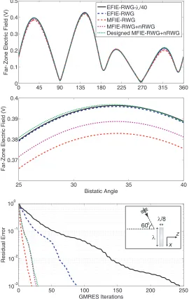
We continue with the scattering from the rectangular box at 500 MHz. Fig. 2 presents the far-zone electric field with respect to the bistatic angle θ on thez-x plane. A focused (zoomed) plot is used to clearly demonstrate the values obtained with different formulations. In addition to the conventional EFIE and MFIE discretized with the RWG functions using the Galerkin scheme (EFIE-RWG and MFIE-RWG), we consider an improved MFIE (MFIE-RWG+nRWG) that is based on using the superpositions of RWG and nRWG functions as testing functions. These conventional results are compared with the designed MFIE, where both RWG and nRWG functions are employed as templates. We note that 16 integration samples are used for EFIE-RWG and MFIE-RWG (P = 16 in (2)), while a total of 32 integration samples are used for MFIE-RWG+nRWG and the designed MFIE-RWG+nRWG (P = 32 in (2)). Fig. 1 also depicts the residual error with respect to the GMRES iterations for different formulations of the scattering problem. Considering both the far-zone scattering values and iteration histories, we have the following observations.
• EFIE-RWG solutions with different mesh sizes are consistent, verifying the high accuracy of EFIE and its reliability as a reference. As also verified in Table 1, using MFIE-RWG drastically reduces the number of iterations to 21, while the accuracy deteriorates, as seen especially in the zoomed plot.
10 -3 10 -2 10-1 100
Far
Field Relative Error
400 450 500 550 600
101 102
Frequency (MHz)
GMRES Iterations
EFIE-RWG MFIE-RWG MFIE-RWG+nRWG
Designed MFIE-RWG+nRWG
z 60o
x 7.5 cm
60 cm
• Adding nRWG testing and increasing the number of testing samples in MFIE to 32 per triangle improves the results in terms of accuracy, while the number of iterations reaches to 27. At the same time, the far-zone scattering values still involve errors in comparison to EFIE.
• By numerically constructing the testing function, the accuracy of MFIE significantly improves to the levels of EFIE. The number of iterations increases only from 27 (for MFIE-RWG+nRWG) to 30 (for the designed MFIE-RWG+nRWG).
3.3. Multi-Frequency Applications
As shown in the examples above, numerically constructed testing functions lead to significant improvements on the accuracy of MFIE without deteriorating the efficiency of iterative solutions. At the same time, the direct approach shown in this paper requires the solution of the same problem using EFIE; hence, it is not useful for the analysis of a single scenario. Specifically, for a single-frequency application, the total number of iterations is not reduced in comparison to EFIE, since the EFIE solution is already needed in the design procedure. On the other hand, the designed functions can further be used in alternative cases, making the design procedure beneficial for accurate and efficient solutions of multi-frequency problems. As an example, Fig. 3 presents the performances of different formulations and discretizations for the solution of scattering problems involving the rectangular box. A total of 21 solutions are performed in the frequency range from 400 MHz to 600 MHz using EFIE-RWG, MFIE-RWG, MFIE-RWG+nMFIE-RWG, and the designed MFIE-RWG+nRWG that is constructed at 500 MHz. The relative error is calculated as described in (10) considering a reference EFIE-RWG with dense (λ/40 at 500 MHz) discretization. It can be observed that the designed MFIE-RWG+nRWG maintains its advantages (higher accuracy compared to MFIE-RWG and MFIE-RWG+nRWG, and faster solutions compared to EFIE-RWG) in the entire frequency range, except at around 560 MHz where an unavoidable internal resonance is detected.
450 500 550 600
101 102
Frequency (MHz)
GMRES Iterations
10
400 10-3 10-2 10-1
0
Far-Field Relative Error
z 60o
x
MFIE-RWG U EFIE-RWG MFIE-RWG+nRWG U EFIE-RWG
Designed MFIE-RWG+nRWG U EFIE-RWG
7.5 cm
60 cm
In multi-frequency applications, we observe no degradation in the performances of the designed testing functions in the considered frequency ranges. In fact, when the frequency becomes very high, the discretization must be changed and refined in consistence with the reduced wavelength. Then, the testing functions must be redesigned on the new discretization. Similarly, discretizations may need to be updated at very low frequencies to avoid the fine-discretization (low-frequency) breakdown of EFIE, again requiring the redesign of testing functions. Apart from these natural limits due to the discretization size itself, the designed testing functions seem to work effectively without any deterioration in the entire frequency ranges.
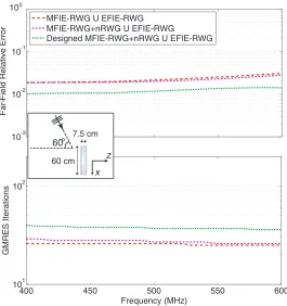
3.4. Designed Testing Functions for CFIE
Finally, we investigate the accuracy of CFIE to demonstrate the improvements via the numerically designed testing functions. Fig. 4 depicts the relative error and the number of GMRES iterations with respect to frequency for the scattering problems involving the rectangular box. In addition to the standard CFIE (EFIE-RWG∪MFIE-RWG), we consider combinations of MFIE-RWG+nRWG and the designed MFIE-RWG+nRWG with EFIE. In all combinations, EFIE and MFIE are weighted equally. It can be observed that, using the testing functions designed at 500 MHz, CFIE provides more accurate results, while keeping the number of iterations at low levels in comparison to EFIE (see Fig. 3 for the corresponding EFIE results). The results are more dramatic for the fishnet structure described in Fig. 1. As depicted in Fig. 5, the testing functions designed at 250 THz reduces the error significantly in the entire frequency range from 200 THz to 300 THz, while the number of iterations is kept at low levels in comparison to EFIE. The error is calculated as described in (10) using a reference EFIE-RWG solution with λ/30 discretization (at 250 THz) and 43,866 unknowns. For this challenging structure, the conventional CFIE implementations (EFIE combined with MFIE-RWG and MFIE-RWG+nRWG) have relative errors as large as 10% that may not be acceptable.
200 225 250 275 300
101 102
Frequency (THz)
GMRES Iterations
10 -3 10 -2 10 -1 100
Far-Field Relative Error
MFIE-RWG U EFIE-RWG MFIE-RWG+nRWG U EFIE-RWG
Designed MFIE-RWG+nRWG U EFIE-RWG EFIE-RWG
x 30o
z
3.175μm
4. CONCLUSIONS
We present a novel approach for improving the accuracy of MFIE and CFIE via numerically constructed testing functions. As opposed to analytical treatments, we design the testing functions at numerical levels, where the compatibility of MFIE systems are tuned in to EFIE solutions. We present a direct approach, where an EFIE solution is performed at a single frequency, and then the constructed testing functions are used at multiple frequencies for accurate and efficient solutions. Hence, while the proposed approach is not directly useful at single frequencies, it is beneficial for multi-frequency applications, where the accuracy of MFIE and CFIE is significantly improved in frequency ranges, without resorting to reimplementations via a complete change of testing functions.
ACKNOWLEDGMENT
This work was supported by the Scientific and Technical Research Council of Turkey (TUBITAK) under the Research Grants 113E129 and 114E498, and by the Turkish Academy of Sciences (TUBA).
REFERENCES
1. Cools, K., F. P. Andriulli, D. De Zutter, and E. Michielssen, “Accurate and conforming mixed discretization of the MFIE,” IEEE Antennas Wireless Propag. Lett., Vol. 10, 528–531, 2011. 2. Erg¨ul, ¨O. and L. G¨urel, “Improving the accuracy of the MFIE with the choice of basis functions,”
Proc. IEEE Antennas and Propagation Soc. Int. Symp., Vol. 3, 3389–3392, 2004.
3. Ubeda, E. and J. M. Rius, “MFIE MOM-formulation with curl-conforming basis functions and accurate kernel integration in the analysis of perfectly conducting sharp-edged objects,” Microw. Opt. Technol. Lett., Vol. 44, No. 4, 354–358, Feb. 2005.
4. Erg¨ul, ¨O. and L. G¨urel, “Improving the accuracy of the magnetic field integral equation with the linear-linear basis functions,”Radio Sci., Vol. 41, RS4004, Jul. 2006.
5. Ubeda, E. and J. M. Rius, “Novel monopolar MFIE MoM-discretization for the scattering analysis of small objects,” IEEE Trans. Antennas Propag., Vol. 54, No. 1, 50–57, Jan. 2006.
6. Erg¨ul, ¨O. and L. G¨urel, “Linear-linear basis functions for MLFMA solutions of magnetic-field and combined-field integral equations,” IEEE Trans. Antennas Propag., Vol. 55, No. 4, 1103–1110, Apr. 2007.
7. Andriulli, F. P., K. Cools, H. Bagcı, F. Olyslager, A. Buffa, S. Christiansen, and E. Michielssen, “A multiplicative Calderon preconditioner for the electric field integral equation,” IEEE Trans. Antennas Propag., Vol. 56, No. 8, 2398–2412, Aug. 2008.
8. Rao, S. M., D. R. Wilton, and A. W. Glisson, “Electromagnetic scattering by surfaces of arbitrary shape,” IEEE Trans. Antennas Propag., Vol. 30, No. 3, 409–418, May 1982.
![Figure 1.Two scattering problems that are considered in this study.A rectangular box with60 cm × 60 cm × 7.5 cm dimensions is investigated at around 500 MHz.A fishnet structure [9] isinvestigated at around 250 THz](https://thumb-us.123doks.com/thumbv2/123dok_us/1984560.1262346/3.612.168.453.80.250/scattering-problems-considered-rectangular-dimensions-investigated-structure-isinvestigated.webp)